Advertisement
RE3 and RE6 RF System Instruction Manual
The RE3 and RE6 radio units are designed to provide highly dependable, consistent wireless
performance. The unit is virtually maintenance free, and is built with quality components geared
towards durability, reliability, and a prolonged operational lifespan.
Operation:
The systems provide a simple, cost effective solution to the inherent weaknesses associated with wired
control systems. The table on the following pages details your system's exact operational behavior.
The system can be used to drive actuators, open/close gates, drive hydraulic cylinders, open/close
valves, etc. Virtually any application that requires an electrical input can be controlled by the RE3/RE6
unit, and our application specific firmware programming capabilities can yield countless variants of
system behavior such as delayed on/of, system time-out auto off, momentary or latched output
configurations, combined outputs, RF system on/off, etc. First, mount the unit in an area that offers as
much protection as possible. (away from sources of high heat, moisture, vibration, electromagnetic,
etc.) The unit is designed to perform effectively in harsh environments, but protecting the unit further
guarantees proper performance and a lengthy operational lifespan. DO NOT mount the receiver unit
with the plug facing upward. Mount the receiver with the plug facing downward where possible. The
receiver's connector is IP rated, and offers a high level of ingress protection, but mounting the receiver
with the plug facing downward further protects against corrosion, water damage, and electrical shorts.
To operate the unit, connect the ground wire (black) to a ground source; be sure to connect to an
effective ground source or your system will not operate properly. Next, connect the receiver to a main
power source (either switched or direct) via its red power wire (pin 1). Where possible, you should
incorporate a switch into the receiver's main power wire as it draws small amounts of current when it is
stand-by mode, and may discharge your battery if left unattended for long periods of time. You may
also use a trickle charger or battery tender on the battery to avoid potential battery drain. There is a 7.5
Amp fuse incorporated into the power lead. DO NOT REPLACE WITH A HIGHER AMPERAGE FUSE
– USE 7.5 AMP FUSE ONLY. Next, connect the appropriate harness output wires to your
device\devices. (IMPORTANT: see power management notes below) Finally, connect the wire harness
plug into the receiver unit plug. - Apply power to the unit, (the red LED will flash four times on power-
up) and you're ready to operate. Using the provided transmitter, the LED on the transmitter, and the
LED on the receiver should illuminate each time an active button on the transmitter is depressed.
Subsequently, via the transmitter, you should generate the desired output. For difficulties, first check
the fuse in the main power wire. Check the device wiring, especially the power & ground connections,
and also check the batteries in the transmitter. If all items are getting power, try the system "learn" &
"memory clear" procedures. If all those efforts fail, feel free to contact our customer support center at
515-264-1808.
Battery Replacement:
During standard operation of the wireless unit, when you depress a button on the keyfob transmitter
(any button assigned a function) the LED indicator on the keyfob will illuminate. Should the LED not
illuminate, this is an indicator that battery voltage has dropped below 2.0 volts, and it is time to replace
the battery. It is suggested that you change the battery (coin cell battery #CR2032) in the key fob
Advertisement
Table of Contents

Subscribe to Our Youtube Channel
Related Manuals for Rowe RE3

Summary of Contents for Rowe RE3
- Page 1 The system can be used to drive actuators, open/close gates, drive hydraulic cylinders, open/close valves, etc. Virtually any application that requires an electrical input can be controlled by the RE3/RE6 unit, and our application specific firmware programming capabilities can yield countless variants of system behavior such as delayed on/of, system time-out auto off, momentary or latched output configurations, combined outputs, RF system on/off, etc.
- Page 2 Some customers prefer to have multiple transmitter controls for their units. Each RE3 is capable of handling and responding to multiple (up to five) transmitters; you simply have to “learn” in each transmitter to your receiver unit.
- Page 3 The total maximum allowable current handling capability for each system, at any given instance, is as follwows: RE3 System- 5.5Amps / RE6 System 7.5Amps Exceeding these limits will result in damage to the unit. For applications needing higher amperage, the RF systems can easily be used in conjunction with a relay/contactor that is suitably rated to the higher amperage load.
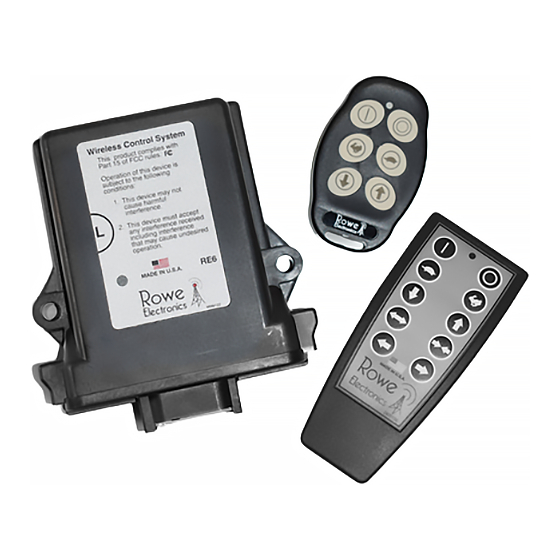
- Page 4 RE3/RE6 Wireless Control Systems RE3 Receiver Unit Receiver “Learn” Area Receiver LED Window Signal Transmission LED Key Fob Transmitter Unit...
Need help?
Do you have a question about the RE3 and is the answer not in the manual?
Questions and answers