Table of Contents
Advertisement
Quick Links
AUTO PILOT SYSTEM
SAS-70
Instruction Manual
Chapter 1. Preview ......................................................................................................5
1.1 About SAS-70 ............................................................................................................................... 5
1.2 Possible interference to Electronic Compass from outside .............................................. 5
1.3 Accuracy on Plotter mode ....................................................................................................... 5
1.4 Characteristics of SAS-70......................................................................................................... 5
Chapter 2. Brief Manual for SAS-70........................................................................6
2.1 Manual Steering ........................................................................................................................... 7
2.2 Compass Steering ........................................................................................................................ 7
2.3 Plotter Steering ............................................................................................................................ 7
2.4 Remote Steering........................................................................................................................... 7
2.5 Dial Steering ................................................................................................................................. 7
2.6 Wave Height Ratio set ................................................................................................................ 8
2.7 Rudder Angle Ratio set .............................................................................................................. 8
2.8 Deviation Correction ................................................................................................................... 8
2.9 Product Spectification................................................................................................................. 8
Chapter 3. Cautions with handling..........................................................................9
3.1 Cautions while using ................................................................................................................... 9
3.2 Cautions while installation ......................................................................................................... 9
3.1.2 Installation for direction sensor ...................................................................................................... 9
3.1.3 Installation for Solenoid valve.......................................................................................................... 9
3.1.4 Installation for Transmitter...............................................................................................................10
3.1.5 Hydraulic piping ...................................................................................................................................10
3.1." Electric Wiring........................................................................................................................................10
Chapter 4. How to operate .................................................................................... 11
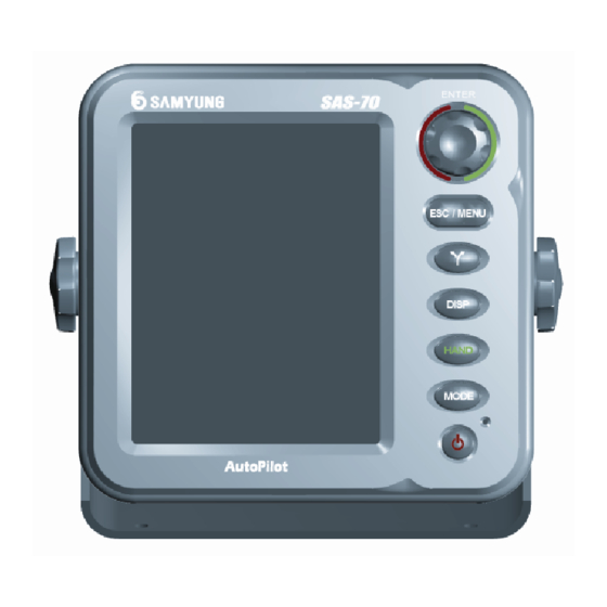
4.1 Function of front panel button for a display unit............................................................... 11
4.2 Configuration of Menu............................................................................................................. 12
4.2.1 Menu..........................................................................................................................................................12
4.2.2 Set for adjust ratio ..............................................................................................................................12
4.3 Screen of Display unit............................................................................................................... 13
4.4 MANUAL STEERING (HAND) ................................................................................................... 14
4.5 COMPASS STEERING ................................................................................................................. 14
4.6 PLOTTER STEERING ................................................................................................................... 15
4.7 REMOTE STEERING .................................................................................................................... 15
4.8 DIAL STEERING........................................................................................................................... 15
4.9 AVOIDANCE / ROTATION ......................................................................................................... 16
4.10 TYPES OF SCREENS FOR OTHER NAVIGATION INFORMATION...................................... 16
4.11 ADJUSTMENT OF VARIATION ............................................................................................... 17
4.12 ADJUSTMENT OF WAVE HEIGHT RATIO ............................................................................. 17
4.13 ADJUSTMENT OF RUDDER ANGLE RATIO .......................................................................... 18
1
CONTENTS
2
Advertisement
Table of Contents

Subscribe to Our Youtube Channel
Summary of Contents for Samyung ENC SAS-70
-
Page 1: Table Of Contents
1.2 Possible interference to Electronic Compass from outside ..........5 1.3 Accuracy on Plotter mode ....................... 5 1.4 Characteristics of SAS-70......................5 SAS-70 Chapter 2. Brief Manual for SAS-70................6 2.1 Manual Steering ........................... 7 2.2 Compass Steering ........................7 2.3 Plotter Steering ..........................7 2.4 Remote Steering........................... - Page 2 Chapter 8. Warranty....................65 9.1 Alert Function..........................38 ☞ Thank you for your purchasing of Auto Pilot manufactured by Samyung ENC. 9.2 Remote Alert Funtion for adjustment ................... 38 ☞ Pay attention to navigation owing to there is no alert function for collision on this unit.
-
Page 3: Chapter 1. Preview
Chapter 1. Preview Chapter 2. Brief Manual for SAS-70 1.1 About SAS-70 SAS-”0 is an automatic marine navigation system that is developed by SAMYUNG ENC CO., LTD. and will make Compass cable FUSE 3A Power ON/OFF you ease to control the ship when it is mounted in small vessel with canalizing the whole information like ships location, ships direction, true speed, the route to navigate, the direction to navigate and the direction of magnetic north radar. -
Page 4: Manual Steering
2.1 Manual Steering 2.6 Wave Height Ratio set The wave height ratio should be adjusted according to the height of wave. Auto mode converses to Manual mode if you press button. Put 0 in low wave, 8 in high wave. Recommend you Manual Steering mode in following environments. -
Page 5: Chapter 3. Cautions With Handling
Don’t smash remote controller against floor or wall. 3.2 Cautions while installation 3.1.1 Installation for display unit of SAS-70 Don’t mount control amplifier at the place where could cause trouble to drive ship. Avoid high vibrating places, high temperature, sea water and rain. -
Page 6: Chapter 4. How To Operate
4.2 Configuration of Menu Chapter 4. How to operate 4.2.1 Menu 4.1 Function of front panel button for a display unit Describe names, function of front panel. 1. Adjustment 1. Compass 2. System setup 1. Language 2. Rudder 2. Night mode 3. -
Page 7: Screen Of Display Unit
4.3 Screen of Display unit ① 4.4 MANUAL STEERING (HAND) ② ④ ③ ⑤ Manual steering means that there is no control from auto steering ⑥ device, and ship is under control of an operator. The relative information as such navigation is shown as current status in a screen. ⑦... -
Page 8: Plotter Steering
Wind direction / speed screen, Gauge screen, Tank screen works well in being equipped with sensor working direction of solenoid valve will be displayed. device of being sold as an optional item by Samyung ENC. (Refer to the instruction manual of the 3. Heading bearings and Rudder angle are shown at indicator of dial sensor device for how to operate .) -
Page 9: Adjustment Of Variation
4.13 ADJUSTMENT OF RUDDER ANGLE RATIO 4.11 ADJUSTMENT OF VARIATION The range: 0.1~3.0 (29 steps) The range: Normal = 1.5 -4 ~ +4 Normal = 0 < Figure 4-5. Adjustment of Rudder Angle ratio > < Figure 4-3. Adjustment of Variation > The adjustment should be set in accordance with size, weight of ship, wind, wave, current Users need to adjust by dialing the dial with more detail even if it was adjusted by and so on and especially, it is affected by wave, wind, current. -
Page 10: Functions Of Remote Controller
Chapter 5. System Installation 4.15 FUNCTIONS OF REMOTE CONTROLLER 5.1 BEFORE INSTALLATION Avoid mounting as follows 4.15.1 Remote Controller of RC-10A Exposed to rain or sea water Difficult places to check, to repair and to plumb. Exposed to direct rays and hot temperature Exposed to severe vibration like near by engine Shows current heading bearings of own ship. -
Page 11: Installation For Compass Sensor (Electronic Compass)
5.3.2 Installation for Compass sensor (Electronic Compass) 5.3.4 Installation for Transmitter To install direction sensor, keeping it away from the place where not only there is Any directions are available for installation direction of transmitter (angle sensor) but magnetism effecting to sensor performance but also solenoid valve, motor or electric following instructions are recommended. -
Page 12: Chapter 6. Hydraulic Piping
steering mode, you need to adjust it if the rudder movement is too speedy or too slow. Chapter 6. Hydraulic Piping The oil controller is installed in the bottom part of the solenoid valve. 6.1 Before Hydraulic piping Refer to the Piping Diagram to ensure that there is nothing wrong about the piping. Connect carefully the joints of the copper pipe and each part to the direction of the sleeve. -
Page 13: Piping Diagram At A Cylinder Type
Cylinder Solenoid Valve Solenoid Valve B Helm Conneting rod Tiller Rudder Feedback Oil Tank STBD Cylinder Solenoid Valve A Tiller Rudder Feedback Conneting rod PORT Cylinder Oil Pump < Figure “-5. (Right) Piping diagram at a cylinder type > < Figure “-3. Piping diagram after installation for Solenoid valve > 6.4 Piping diagram at a cylinder type When the oil-pressure is given in the pipes connected to the solenoid, the Left(B) pipe is the pipe to which the ship direction turns left while the Right(A) pipe is the pipe to which the ship direction turns... -
Page 14: Chapter 7. Electric Diagram
Chapter 7. Electric Diagram Chapter 8. Initial Setup after installation 7.1 Before hydraulic piping 8.1 Initial setup As the equipment s delivered from the factory, going through all the detailed adjustments, users are Before setting the wires, please abide by the following instructions. Improper handling may cause any not required to set up the most functions but the setup of functions as such solenoid valve, compass, serious electric shocks or damages to the equipment. -
Page 15: Rudder Setup
8.1.2 Rudder setup max 40 of left by rolling handle of manual steering. The value of screen is changeable in accordance with angles to be rolled by the steering. Move a cursor onto [SELECT], save a value by pressing button. Select [ESC] to cancel the value then the previous value is kept. -
Page 16: Remote Setup
① Only available with a case being equipped with Rudder Angle Indicator. Match ① ① Match to max 40 of left direction by rolling Remote controller. Rudder on exact center by rolling the steering wheel and adjust the arrow of rudder ②... -
Page 17: System Setup
does not match with earth's north/south pole exactly. (The Republic of Korea's variation is around +”.) depends on user. A standard direction for revision should be true north and should be revised by GPS or GPS ① Set wave height ratio from 0° to 355° with 5° range and revise the difference by Plotter. -
Page 18: Option, Warning, Measurement
“ System info. Enable to view of system information MENU FUNCTION ” Update Only available function for registered engineers It consists of 2 screens to supervise basic data input by this pilot system and Initial setup Return all set values to an initial factory status System other information both. -
Page 19: Self Test
Chapter 9. Funtions of Alert and Trouble indicator 8.2 Self Test 9.1 Alert Function SAS-”0 provide information as such out of route, no heading signal, low power voltage The self testing value can vary each time, and the numbers can be used by specialists in SAMYUNG alert, waypoint, auto navigate alert etc. -
Page 20: Sm-975A Electronic Lever
An engine related equipment controlling vessels` speed and forward/ backward clutch among vessel 1.4 Terms and abbreviation automation equipment that is provided by Korean domestic technology of SAMYUNG ENC CO., LTD. SM-9”5 can be used independently and controlled by remote control. Further, it can be connected 1.4.1 Terms Explanation... -
Page 21: Chapter 2. System Installation
Chapter 2. System Installation 2.2 How to connect Control cables 2.1 Installation of Control Cables Configuration of link cables for engine governor and clutch is as follow picture. Clutch cable Diagram Governor cable Diagram Clutch lever Governor lever Manual lever Electronic lever Clutch lever Governor lever... -
Page 22: Cable Connection To Manual Lever
For best performance of motion of manual clutch lever , link point of "①" on above picture should be selected properly. a) When the manual clutch lever is on forward position, location of the lever has to Clutch lever Governor lever be forwarded by pushing it. -
Page 23: Drawing For Wiring Connection (Connected To Auto Pilot)
2.6 Drawing for wiring connection (Electronic lever separate type) 2.5 Drawing for wiring connection (Connected to Auto Pilot) In case installing this electronic lever separately, the drawing is as followings. In case of electronic lever (engine control unit) installation with auto steering controller In installing with single type, the relative wiring for auto pilot is not used among cables (SAS-”), the way of electric wiring follows as the below picture. -
Page 24: Chapter 3. Initial Setup After Installation
Chapter 3. Initial setup after installation 3.2 Operating setup (Setup + Power ON) With ship's engine is off, check all electric wire, portable transmitters wire and fushlble 3.1 Controller for initial setup cable locking condition, set operation/set switch [set] position. button Function Operation... - Page 25 ④ Press ▲ switch or ▼ switch to control Clutch lever of Control lever(manual ③ Set clutch controller of remote controller to [N] position. controller) to be [AHEAD]position. ④ Press ▲ switch or ▼ switch to control Clutch lever of Control lever(manual ⑤...
-
Page 26: Functional Setup (Setup + Select + Power On)
④ In case of not the initial set, set operation/set switch to [operation]. After power off, ① Check if operation/set switch is [set] mode. switch on after 5 seconds. It would be back to normal operation. ② Press choice switch to set “ on indicator. Caution As setting with engine start-off, test auto scope by manual lever before set, ③... -
Page 27: Chapter 4. How To Operate
Chapter 4. How to Operate 4.1 Functions for Remote Controller Caution If clutch is AHEAD or ASTERN but NEUTRAL, after that set clutch approximately after 1 second, set engine revolving speed automatically at same level of governor control position of remote control. Approximately, as 10% (Governor slow speed to full speed Clutch controller: Locating in the middle is one-hundredth percentage) is increased at 1 second, full revolving speed is increased at 5 진... -
Page 28: Chapter 5. Drawing For Sm-975A
Engine DC 20 ~ 40V SB-TWIN OPTION 5.2 Outline drawing for Remote Controller 5.3.2 Auto Steering / Electronic Lever (SAS-70+SM-975A) ““mm ”0mm D isp lay R em o te C o n tro l E lectric C o m p a ss SA S-”... -
Page 29: Connecting Diagram For Electonic Lever
Chapter 6. PACKING LIST 5.4 Connecting diagram for Electonic lever 6.1 SAS-70 SAS-”0 (1/2) Name of Product Shape Specification Check Remark SAS-”0 Display unit 1 EA A-10 (Bracket for fix) CODE NO. SAS-”0 SAS-”0C Controller 1 EA CODE NO. SAS-”0C SAS-”0A... -
Page 30: Sas-70 Option(In Case Of Additional Sm-975A)
6.2 SAS-70 OPTION(In case of additional SM-975A) SAS-”0 (2/2) Name of Product Shape Specification Check Remark SM-9”5A (1/1) Ø4 X 1“mm(반달 머리) 1” 1 type stand fix Name of Product Shape Specification Check Remark CODE NO. SM-50“4 Ø3 X 1“m(반달 머리) SAS-”0C... -
Page 31: Chapter 7. Products Drawings
-0.5 INDICATOR (FM-80B) Auto-Pilot DISPLAY (SAS-70) Solenoid Valve (SV-20) B=BLACK, W=WHITE, R=RED, G=GREEN, [S]=SHIELD Connect black and white of solenoid valve in reverse in case of operation of the rudder Connect red and white of transmitter in reverse in case of operation of the Rudder Angle Indicator... - Page 32 36.5 225.6...
-
Page 33: Chapter 8. Warranty
Chapter 8. Warranty Thank you for your purchasing of Auto Pilot manufactured by Samyung ENC. This instruction manual shows how to install for this system and correct method for installation and any cautions. I would like to request you to keep this manual book on a safe place to avoid loss or lost. Please provide this manual book to the authorized person when you sell or provide the unit to other ones.
Need help?
Do you have a question about the SAS-70 and is the answer not in the manual?
Questions and answers