Table of Contents
Advertisement
Quick Links
Advertisement
Table of Contents

Summary of Contents for Summit SFC-102 Series
- Page 1 SFC-102 SERIES FIRE ALARM PANEL INSTALLATION INSTRUCTIONS LT-2015SUM Rev.1...
-
Page 3: Table Of Contents
SFC-102 Installation & Operator’s Manual Table of Contents 1.0 Introduction ........................1 1.1 The SFC-102 Fire Alarm Control Unit ................1 1.2 Codes, Standards and Installation Requirements ............1 1.3 Technical Support and General Information ..............2 1.4 System Verification ....................... 2 1.5 Standby Power ...................... - Page 4 SFC-102 Installation & Operator’s Manual 9.0 Appendix: Table of Compatible Smoke Detectors ............33 9.1 Smoke Detector Bases ....................35 9.2 Compatible 4-Wire Smoke Detectors ................35 9.3 Compatible Horns/Strobes .................... 36 FCC Compliance Statement ....................38 Warranty & Warning Information ..................39 Warning Please Read Carefully ..................
- Page 5 SFC-102 Installation & Operator’s Manual List of Figures Figure 1: SFC-102 cabinet with door closed ............... 4 Figure 2: SFC-102 display and controls ................4 Figure 3: SFC-102 Cabinet Overview ................. 4 Figure 4: Zone Label Insert ....................4 Figure 5: Panel Assembly and Modules Locations ............. 8 Figure 6: Mounting Dimensions ..................
-
Page 7: Introduction
SFC-102 Installation & Operator’s Manual 1.0 Introduction 1.1 The SFC-102 Fire Alarm Control Unit General features •Two initiating device circuits, class B / style B •Two notification appliance circuits, class B / style Y (Power Limited) [can be wired as one NAC, class A / style Z] •One common alarm-actuated relay, form ‘C’... -
Page 8: Technical Support And General Information
1.3 Technical Support and General Information For technical support call 1866-SUMMIT-0(1-866-786-6480), or email techsupport@summit-st.net For general product information visit the Summit web site: www.summit-st.net. 1.4 System Verification The complete fire alarm system must be verified for proper installation and operation when: •the initial installation is ready for inspection by the Local Authority Having Jurisdiction;... -
Page 9: Preparing To Install The Sfc-102 Fire Panel
SFC-102 Installation & Operator’s Manual 2.0 Preparing to Install the SFC-102 Fire Panel 2.1 Unpacking the SFC-102 The basic SFC-102 package includes the following components: •Cabinet with hinged door •Display and control plate c/w display and control printed circuit board. •Zone label insert •Battery compartment dead front plate •Main control PCB... -
Page 10: Sfc-102 Overview
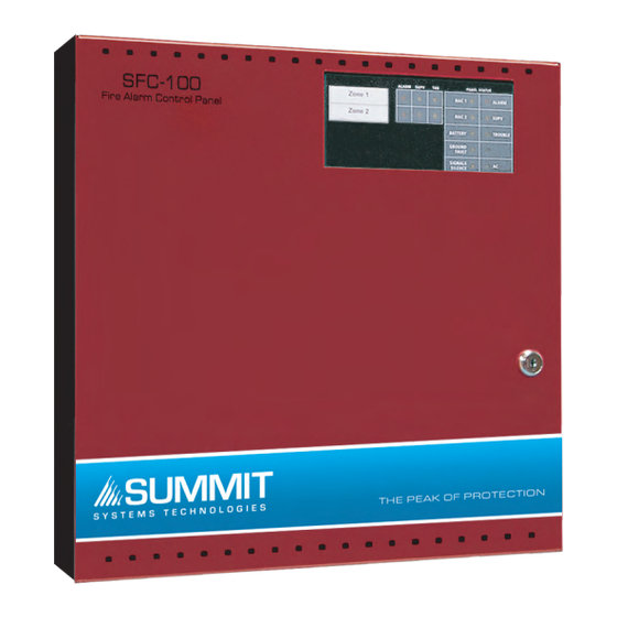
SFC-102 Installation & Operator’s Manual 2.3 SFC-102 Overview FAULT Figure 1: SFC-102 cabinet with door closed Figure 2: SFC-102 display and controls Note: Use Security Screw(SPAENAUR #381-064) provided to meet UL 864 Rev 9 requirement Figure 3: SFC-102 Cabinet Overview Zone Label Insert A zone label insert is installed in the zone window area. -
Page 11: Planning Your Installation
SFC-102 Installation & Operator’s Manual 2.4 Planning Your Installation Note: This system should be installed and serviced by qualified fire alarm installation professionals. As a minimum, the following points should be considered to ensure that the installation will be successful and proceed without delay. -
Page 12: Module Current Ratings
SFC-102 Installation & Operator’s Manual 2.6 Module Current Ratings Standby Max. Alarm Alarm Current Module Current (mA) Current (mA) (mA) DC SFC-102 Control panel 425(*) SRTI-100 Remote trouble indicator SRAM-105 R.T.I. and remote 5 zone annunciator 20(*) SUDACT-100 DACT SRM-103 Relay module(**) Note: *Current noted assumes ONE initiating zone is in alarm. -
Page 13: Calculation For Standby Battery Requirement
SFC-102 Installation & Operator’s Manual 2.8 Calculation for Standby Battery Requirement Total Total Alarm Current per Number Step Device Standby Current device (mA) of device Current (mA) (mA) Standby: = 90 SFC-102 Alarm: Standby: Zone 1 Alarm: Standby: Zone 2 Alarm: NAC 1 Alarm:... -
Page 14: Installing The Sfc-102 Fire Panel
SFC-102 Installation & Operator’s Manual 3.0 Installing the SFC-102 Fire Panel 3.1 Environmental Specifications Consider the following conditions when selecting a mounting location for the SFC-102 panel: •Operating temperature: 32°F to 122°F / 0°C to 50°C •Humidity: 95% RH non-condensing •Close to a source of unswitched AC power 3.2 Panel Assembly and Modules Locations The panel comes completely assembled from the factory. -
Page 15: Mounting The Sfc-102
SFC-102 Installation & Operator’s Manual 3.3 Mounting the SFC-102 Figure 6: Mounting Dimensions Dimensions in inches Figure 7: Knockout Locations... -
Page 16: Wiring The Sfc-102
SFC-102 Installation & Operator’s Manual 4.0 Wiring the SFC-102 4.1 Wiring Specifications Figure 8: SFC-102 Terminal Descriptions Terminal Description Label Notification Appliance Circuit # 1 24 V , Full-Wave Rectified voltage, 1.5 Amps max. NAC 1 Programmable as Steady or Temporal output on alarm. (+, –) Supervised for opens, shorts and ground fault. -
Page 17: Figure 9: Connecting 2-Wire Alarm Initiating Devices
SFC-102 Installation & Operator’s Manual Terminal Description Label Common Alarm relay, Normally Closed contact The Common Alarm relay is normally de-energized. ALM NC Contact is shown in the de-energized state. Contacts are rated 30 V , 2 Amps max. Zone 1 positive input Zone 1 negative input Zone output is 24 V nominal to power 2-wire smoke detectors. -
Page 18: Connecting Nac Devices (Class 'A' And Class 'B')
SFC-102 Installation & Operator’s Manual Figure 10: Connecting 4-Wire Smoke Detectors 1. Program as zone type 01, instant alarm. 2. Maximum total loop wire resistance is 100 ohms. Zone Wiring Chart: Wire Distance Distance (Gauge) (feet) (meters) 7,690 2,345 Maximum loop resistance is 12,195 3,717 100 ohms. -
Page 19: Figure 13: Connecting Batteries
SFC-102 Installation & Operator’s Manual NAC Wiring Chart Maximu 18-Awg 16-Awg 14-Awg 12-Awg Maximum Wire Wire Wire Wire Total Loop Current (ohms) 8.00 0.25 1,538 2,500 5.00 0.50 1,250 2.70 0.75 2.00 1.00 1.60 1.25 1.30 1.50 Note: This chart is based on a minimum source voltage of 22 volts and a maximum line loss of 2 volts thus leaving a minimum of 20 volts at the last notification appliance. -
Page 20: Figure 15: Connecting The Alarm And Trouble Relays
SFC-102 Installation & Operator’s Manual Figure 15: Connecting the Alarm and Trouble Relays Figure 16: Connecting Optional Devices See installation sheets for the remote devices for detailed wiring and address setup. 1. Maximum of 4 MR-2605-T per panel. 2. Maximum of 4 MR-2605-AT per panel. Secur-bus Wiring Chart 22-awg Wire 18-awg Wire... - Page 21 SFC-102 Installation & Operator’s Manual To calculate the wire run distance for any gauge wire and any maximum current value, use the following formula: 1.25 Remix = ohms Immix Amps Remix × 1,000 Distance = feet 2(wire resistance in ohms per 1,000 feet) Secur-bus Capacitance Maximum wire capacitance for proper operation of the Secur-bus is 90 nF (nanofarad).
-
Page 22: Panel Operation
SFC-102 Installation & Operator’s Manual 5.0 Panel Operation 5.1 Operating Sequences This section describes how the panel functions under various conditions. The choices you make in panel programming will also affect how the panel operates. Please see for information on how to program the panel, and descriptions of each of the programming options. -
Page 23: Supervisory Zone Alarms
SFC-102 Installation & Operator’s Manual 5.4 Supervisory Zone Alarms When an alarm occurs on a supervisory zone (type 04), the corresponding zone supervisory LED begins flashing. The common supervisory LED and supervisory relay (supervisory relay is optional) turn on steady, and the buzzer turns on steady. - Page 24 SFC-102 Installation & Operator’s Manual System Troubles Common Trouble System faults Trouble Buzzer Other Indicators Relay sounds ½ Alarm zone open circuit – loss Zone trouble LED turns on second on/ deactivates of EOLR turns on steady sounds ½ NAC1 or NAC2 NAC open circuit or short turns on second on/...
-
Page 25: System Reset Operation
SFC-102 Installation & Operator’s Manual 5.6 System Reset Operation To reset the system, press the ‘Reset System’ button. The panel will remove all power from the zones and the switched auxiliary relay for 10 seconds. During this 10 second period, the buzzer will beep twice every 2 seconds. -
Page 26: Walk Test (Installer Function Only)
SFC-102 Installation & Operator’s Manual 5.8 Walk Test (Installer function only) To do a walk test, all zone alarms, troubles and relays must be in their normal state. You can program the walk test to be either audible or silent (see “Audible Walk Test” on page 26). 1. -
Page 27: Nac Operation
SFC-102 Installation & Operator’s Manual 5.9 NAC operation See also “NAC Temporal/Steady Programming - Section 1 (‘NAC1’ LED on steady)” on page 25, and “NAC Auto-silence and Strobe Programming - Section 2 (‘NAC2’ LED on steady)” on page 25 for more information. Class ‘B’... -
Page 28: Programming The Sfc-105 System
SFC-102 Installation & Operator’s Manual 6.0 Programming the System SFC-105 6.1 How to Program the SFC-105 You can program the panel using the controls and indicator LEDs. There are no DIP switches to set for programming. Once programmed, the operating modes selected are maintained in non-volatile memory that will retain the programmed information even if all power is removed from the panel. - Page 29 SFC-102 Installation & Operator’s Manual When you first enter programming mode, the panel will be at zone programming (section 0). Each programming section has one or more programming sub-sections (e.g. section 0 has sub-sections for zones 1 through 5). Use the Silence Trouble and Silence Alarm buttons to enter your programming choices: 1.
-
Page 30: Programming Section Descriptions
SFC-102 Installation & Operator’s Manual 6.2 Programming Section Descriptions Zone Programming (Section 0) In this zone programming section, the panel uses the zone alarm, supervisory, and trouble LEDs to indicate the programming as follows: FAULT Zone type 00 – Null zone (Not used) The zone is not used. - Page 31 SFC-102 Installation & Operator’s Manual NAC Temporal/Steady Programming - Section 1 (‘NAC1’ LED on steady) You can individually program both NAC1 and NAC2 to sound in either a temporal or steady pattern. By default, both NAC outputs are programmed as steady. Temporal The NAC1 will sound the Temporal/ANSI Fire Pattern: 0.5 seconds ON, 0.5 seconds OFF, 0.5 seconds ON, 0.5 seconds OFF, 0.5 seconds ON, 1.5...
- Page 32 SFC-102 Installation & Operator’s Manual Silence Inhibit and Walk Test Programming - Section 3 (‘Battery’ LED on steady) Signal Silence Inhibit Timer If the Signal Silence Inhibit Timer is enabled, when the first alarm is activated, the panel will begin a 60 second countdown. During this 60 seconds, users will not be able to turn off the NACs by pressing the Silence Alarm button.
-
Page 33: Viewing The Event Buffer
SFC-102 Installation & Operator’s Manual 50/60 Hz Option - Section 5 (‘Signals Silence’ LED on steady) 50/60 Hz Option Reset Section Programming (All common trouble LEDs flashing) To Enter this Programming Section 1. Enter the installer programming mode, section 0 2. - Page 34 SFC-102 Installation & Operator’s Manual Event Buffer Table Display Event Steady Common Alarm LED Null Event Flashing Zone X Alarm LED Verified Zone X Alarm Steady Zone X Alarm LED Verified Zone X Alarm Restore Flashing Zone X Alarm LED and Flashing Zone X Unverified Zone X Alarm Supervisory LED Flashing Zone X Supervisory LED...
-
Page 35: Startup Of The Sfc-105
SFC-102 Installation & Operator’s Manual 7.0 Startup of the SFC-105 7.1 Prior to power up •Verify that all field wiring is free of shorts, opens and grounds and that end-of-line devices are connected and are the proper value. •Verify that all modules and internal cables are properly seated in their location. •Verify that all metal components are bonded to the incoming ground. -
Page 36: Programming Worksheets
SFC-102 Installation & Operator’s Manual 8.0 Programming Worksheets 8.1 Entering Programming Mode Please see “6.0 Programming the SFC-105 System” on page 22 for complete instructions. Note: All zone alarms must be reset prior to entering the programming mode. While the panel is in the programming mode, the annunciators will show a trouble condition. -
Page 37: Zone Programming (Section 0)
SFC-102 Installation & Operator’s Manual 8.2 Zone Programming (Section 0) Program each of the zones as one of the following types. (See “Zone Programming (Section 0)” on page 24.) Record your programming choices in the table below. ZONE Type Zone ALARM (00 - Label... -
Page 38: Silence Inhibit And Walk Test Programming (Section 3)
SFC-102 Installation & Operator’s Manual 8.5 Silence Inhibit and Walk Test Programming (Section 3) Please see “Silence Inhibit and Walk Test Programming - Section 3 (‘Battery’ LED on steady)” on page 26. Settings ZONE ALARM Programming Section LED On Signal Silence Inhibit Timer Enabled *Disabled One Man Walk Test... -
Page 39: Appendix: Table Of Compatible Smoke Detectors
SFC-102 Installation & Operator’s Manual 9.0 Appendix: Table of Compatible Smoke Detectors Max. # Panel Manufacture Model Base Detector Model Base Description Ionization type 1400/ System Sensor smoke, 2-wire 1400A 12/24V Plug-in – B401 System Sensor 1451 Ionization type B401B smoke detector Photoelectric, 2- System Sensor... - Page 40 SFC-102 Installation & Operator’s Manual Max. # Panel Manufacture Model Base Detector Model Base Description Photoelectric, System 2112/24T 12/24V Sensor terminal strip B401 Plug-in – High 4451HT System B401B Temp Heat Sensor 4451HTA 88°C (190°F) DH400 B401 Plug-in – Fixed System 5451 B401B...
-
Page 41: Smoke Detector Bases
SFC-102 Installation & Operator’s Manual 9.1 Smoke Detector Bases Max. # Manufacture Base Model Description Detectors System B401 2-wire standard base, 4”, 12/24V Sensor System B401B 2-wire standard base, 6”, 12/24V Sensor System B406B 2-wire base, 24V , form contact Sensor System B401BH... -
Page 42: Compatible Horns/Strobes
SFC-102 Installation & Operator’s Manual 9.3 Compatible Horns/Strobes Voltage System Sensor Type (FWR) P2415(W)(A) 20-30 P241575(W)(A) 15/75 20-30 P2475(W)(A) 20-30 P24110(W)(A) 20-30 S2415(W)(A) 20-30 S241575(W)(A) 15/75 20-30 S2475(W)(A) 20-30 S24110(W)(A) 20-30 H24(W)(A) 20-30 MDL(W)(A) Module 20-30 No suffix = Red, suffix W = White, suffix A = Canadian version Voltage Gentex... - Page 43 SFC-102 Installation & Operator’s Manual Voltage Wheelock Type (FWR) NS-2415W-FR(W) 20-31 NS-241575W-FR(W) 15/75 20-31 NS-2430W-FR(W) 20-31 NS-2475W-FR(W) 20-31 NS-24110W-FR(W) 20-31 NS4-2415W-FR(W) 20-31 NS4-241575W-FR(W) 15/75 20-31 NS4-2430W-FR(W) 20-31 NS4-2475W-FR(W) 20-31 NS4-24110W-FR(W) 20-31 NS = 2-wire, NS4 = 4-wire AS-2415W-FR(W) 20-31 AS-241575W-FR(W) 15/75 20-31 AS-2430W-FR(W)
-
Page 44: Fcc Compliance Statement
SFC-102 Installation & Operator’s Manual FCC Compliance Statement CAUTION: Changes or modifications not expressly approved by the manufacturer could void your authority to use this equipment. This equipment has been tested and found to comply with the limits for a Class B digital device, pursuant to Part 15 of the FCC Rules. -
Page 45: Warranty & Warning Information
SFC-102 Installation & Operator’s Manual Warranty & Warning Information Warning Please Read Carefully Note to End Users: This equipment is subject to terms and conditions of sale as follows: Note to Installers This warning contains vital information. As the only individual in contact with system users, it is your responsibility to bring each item in this warning to the attention of the users of this system. - Page 46 •Software Most Summit products contain software. With respect to those products, Summit does not warranty that the operation of the software will be uninterrupted or error-free or that the software will meet any other standard of performance, or that the functions or performance of the software will meet the user’s requirements.
-
Page 47: Limited Warranty
Summit management, no credits will be issued for custom fabricated products or parts or for complete fire alarm system. Summit will at its sole option, repair or replace parts under warranty. Advance replacements for such items must be purchased. -
Page 48: Out Of Warranty Repairs
SUMMIT MAKES NO WARRANTY OF MERCHANTABILITY OR FITNESS FOR A PARTICULAR PURPOSE WITH RESPECT TO ITS GOODS DELIVERED, NOR IS THERE ANY OTHER WARRANTY, EXPRESSED OR... - Page 52 THE PEAK OF PROTECTION U.S.A. Canada © Summit 2008 Printed in Canada 4575 Witmer Industrial Estates 25 Interchange Way Subject to change without prior notice Niagara Falls, NY 14305 Vaughan, ON L4K 5W3 www.summit-st.net Tel: 1-866-SUMMIT-0 Fax: 1-888-660-4113 Tel: 905-695-3549 Fax: 905-660-4113...
Need help?
Do you have a question about the SFC-102 Series and is the answer not in the manual?
Questions and answers