Table of Contents
Advertisement
Quick Links
Advertisement
Table of Contents

Related Manuals for IC 3050349

Summary of Contents for IC 3050349
- Page 2 IC Electrical Load Manager 3050349 User Manual Revision Log Date Author Approved Changes 4/17/2015 Initial release Copyright © 2015 Innovative Controls, Inc. All rights reserved. This document contains proprietary information. The ownership of this document and its contents is retained by Innovative Controls, Inc. By supplying this document, Innovative Controls, Inc. neither grants nor waives any right or license to this document or its contents.
-
Page 3: Table Of Contents
IC Electrical Load Manager 3050349 User Manual Table of Contents 1. Features ..............................5 2. Operation ..............................6 2.1 Sequencing ............................6 2.2 Shedding ............................. 6 2.3 Shed and Unshed Voltage Thresholds....................6 2.4 Fast Idle ............................... 6 2.5 Low Voltage Alarm ..........................7 2.6 Vehicle System Inputs ......................... - Page 4 IC Electrical Load Manager 3050349 User Manual 7.2 Load Wiring Example ........................17 8. Accessories ............................. 20 9. Technical Specifications.......................... 21 Page 4 of 21 Rev 1...
-
Page 5: Features
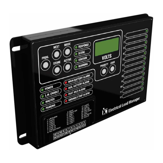
IC Electrical Load Manager 3050349 User Manual 1. Features The Innovative Controls Inc. Electrical Load Manager is used to monitor a vehicle’s battery system and control electrical circuits to meet requirements detailed in NFPA-1901. All adjustments are made from the front panel user interface that also serves as a real-time status display. -
Page 6: Operation
IC Electrical Load Manager 3050349 User Manual 2. Operation 2.1 Sequencing Electrical loads will turn on sequentially in priority order from 1 to 8 when their respective logic switch, either ignition or master warning, is activated and the vehicle is operating in the selected mode, either response and/or scene. -
Page 7: Low Voltage Alarm
IC Electrical Load Manager 3050349 User Manual The Fast Idle output will turn off immediately when either the Load Manager Enable or Parking Brake input is removed. 2.5 Low Voltage Alarm The Low Voltage Alarm output is activated whenever the system voltage drops below 11.9 VDC on a 12 volt system or 23.8 VDC on a 24 volt system for more than 10 seconds. -
Page 8: Operating Voltage Ranges
IC Electrical Load Manager 3050349 User Manual 2.11 Operating Voltage Ranges The Electrical Load Manager can operating voltage range is 7 to 32VDC. 2.12 Manual Override When the Manual Override switch on the side of the Electrical Load Manager is activated load outputs 1 through 12 will turn on regardless of the vehicle operating mode or main battery voltage. -
Page 9: Programming
IC Electrical Load Manager 3050349 User Manual 3. Programming The Innovative Controls Electrical Load Manager configurations are all programmed from the front panel user interface. There are no internal jumpers. A three-digit seven segment display and four LEDs are used to indicate the status of the load manager to the programmer. -
Page 10: Priority Switch
IC Electrical Load Manager 3050349 User Manual Master Warning, and Parking Brake. The “x” value will be either “H” or “L” to indicate high or low side polarity. 3.3 PRIORITY Switch The PRIORITY switch selects the sequence and shed priority level for the selected output. The digital display will show the current priority as the switch cycles through from “P00”... -
Page 11: Input / Output Polarity
“LoC”, release the STORE, MODE, and USER switches and press and hold the PROGRAM button until the display changes to “IC”. To unlock the front panel, simultaneously press and hold the STORE, MODE, and USER switches. After 3 seconds the display will show “ULC”, release the STORE, MODE, and USER switches and press and... -
Page 12: Programming Examples
IC Electrical Load Manager 3050349 User Manual 4. Programming Examples The following programming examples show how to make changes to the Electrical Load Manager’s configuration. 4.1 Programing the Configuration of Load Output #3 The following example shows how to program the load output #3 to shed at 12.0 VDC and only be active when the Master Warning Switch is on and the vehicle is in Scene Mode. -
Page 13: Connections
IC Electrical Load Manager 3050349 User Manual 5. Connections Electrical Load Manager connector viewed from wire insertion end. Terminal Function Polarity Terminal Function Polarity Load Manager Selectable Output Load #2 Selectable Enable Output Load #2 Selectable Output Load #2 Selectable... -
Page 14: Wiring Accessories
IC Electrical Load Manager 3050349 User Manual Electrical Load Manager Part Number Terminal 11 Terminal 12 No Communication 3050349-01 No connection No connection J1939 CAN Bus 3050349-02 CAN High CAN Low RS485 3050349-04 Data + Data - 5.1 Wiring Accessories The following components and tools are available to aid wiring the Innovative Control Inc. -
Page 15: Default Settings
IC Electrical Load Manager 3050349 User Manual 6. Default Settings The Innovative Controls Electrical Load Manager is shipped with the following default settings: The system voltage is set for 12 VDC. The unit will NOT be damaged if it is connected to a 24 VDC system before the system voltage is changed to 24 VDC. -
Page 16: Installation
IC Electrical Load Manager 3050349 User Manual 7. Installation The following section describes the Electrical Load Manager installation details. 7.1 Mounting Dimensions The mounting dimensions for the Electrical Load Manager are shown below. Page 16 of 21 Rev 1... - Page 17 IC Electrical Load Manager 3050349 User Manual 7.2 Load Wiring Example Wiring the Electrical Load Manager to a vehicle’s electrical system can be simplified by using the Innovative Controls 12 Channel Relay Board. Simply install the cab loads switches in series between the Electrical Load Manager and the 12 relay board switch inputs.
- Page 18 IC Electrical Load Manager 3050349 User Manual Page 18 of 21 Rev 1...
- Page 19 IC Electrical Load Manager 3050349 User Manual Page 19 of 21 Rev 1...
- Page 20 IC Electrical Load Manager 3050349 User Manual 8. Accessories The following Electrical Load Manager accessories are available from Innovative Controls Inc. Description Part Number Connector Socket Kit Innovative Controls Inc. 3050353 Mating Pigtail Innovative Controls Inc. 3050352 Remote Cab Display Innovative Controls Inc.
- Page 21 IC Electrical Load Manager 3050349 User Manual 9. Technical Specifications Operating voltage 7 to 32 VDC Power consumption with no loads At 13.8 VDC 120 mA At 27.6 VDC 100 mA Operating temperature range -40°C to +105°C (-40°F to +220°F) Storage temperature range -40°C to +105°C (-40°F to +220°F)
Need help?
Do you have a question about the 3050349 and is the answer not in the manual?
Questions and answers