
Related Manuals for Wiedenmann Terra Clean 160

Summary of Contents for Wiedenmann Terra Clean 160
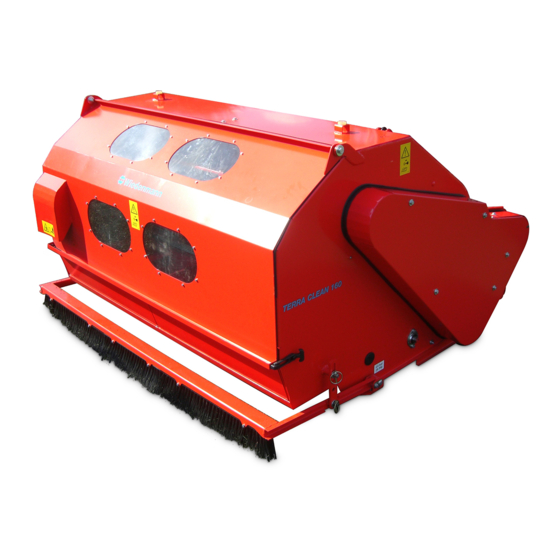
- Page 1 Translation of original Operating Instructions Synthetic Turf Maintenance Machine Terra Clean 160 245.001 From equipment I.D. No. : Status : March 2015 245 99 01...
- Page 2 All information, illustrations and specifications in these Operating Instructions are based on the latest information available at the time of publication. We reserve the right to make design changes at any time without prior notification...
- Page 3 All information, illustrations and specifications in these Operating Instructions are based on the latest information available at the time of publication. We reserve the right to make design changes at any time without prior notification...
- Page 4 Preface READ THESE OPERATING INSTRUCTIONS CAREFULLY to familiarise yourself with the correct way to operate and service your machine, and to prevent personal injury or damage to the machine. These operating instructions can also be obtained in other languages (your dealer can order these for you). THESE OPERATING INSTRUCTIONS ARE a permanent part of your machine and should be handed over to the new owner if the machine is sold.
-
Page 5: Table Of Contents
6.0. Operating............. 38-45 6.1. General information......... 38 6.2. Checking speed and direction of rotation....38 6.3. Power drive of Terra Clean 160......39 6.4. Setting the working depth........39 6.5. Setting the Brush Rail........40 6.6. Check the correct adjustment of the cylinder broom..40 6.7. - Page 6 TABLE OF CO N T E N T S Page * * * * * * * * * * * * * * * * * * * * * * * * * * * * * * * * * * * * * * * * * * * * * * * * * * * 7.0.
-
Page 7: Safety Measures
1.0. Safety Measures RECOGNISE WARNING SYMBOLS This symbol draws your attention to the safety instructions attached to the machine or contained in these operating instructions. It means that there is a risk of injury. Follow all recommended safety instructions as well as the accident prevention regulations. - Page 8 1.0. Safety Measures OBSERVE THE ROAD TRAFFIC REGULATIONS Always observe local road traffic regulations when using public roads. WEAR PROTECTIVE CLOTHING Wear close-fitting clothing and the appropriate safety equipment for the work at hand. Prolonged exposure to loud noise can result in impairment or loss of hearing.
- Page 9 1.0. Safety Measures STAY CLEAR OF ROTATING DRIVE SHAFTS Carelessness in the area of the rotating drive shafts can result in serious injury or even death. Always ensure that all shaft protection devices are fitted i.a.w. regulations and that the universal-joint shaft sheath tubing can turn freely.
- Page 10 1.0. Safety Measures USE SAFETY LIGHTS AND EQUIPMENT Avoid collisions with other road users. Slow moving tractors with mounted or towed equipment, and self-propelled machines on public roads pose a specific danger. Frequently check for traffic coming behind you, especially when making turns. Ensure safe traffic conditions by using hand signals or indicators.
- Page 11 1.0. Safety Measures REMOVE PAINT BEFORE WELDING OR HEATING PARTS Welding should only be carried out by persons with a relevant qualifying certificate i.a.w. EN287. Avoid the formation of toxic fumes and dust. Hazardous fumes can be generated when paint is heated due to welding, soldering, or using a welding torch.
-
Page 12: Adhesive Safety Signs
1.0. Safety Measures 1.1. Adhesive Safety Signs Warning symbols Warning symbols indicating danger are attached at some important areas on the machine. The hazard is identified via a warning triangle. A second symbol informs you how the injury can be prevented by acting appropriately. - Page 13 1.0. Safety Measures 1.1. Adhesive Safety Signs Blow-out cover When operating ensure that sufficient distance is left as there is a risk of injury from thrown or flying objects. 245.02 Maintenance Shut off the engine and remove the key before performing maintenance or repair work.
-
Page 14: Safety Equipment
Do not operate the machine when children and others are nearby. d) Do not allow untrained personnel to operate the machine. ATTENTION DANGER ! Never use the TERRA CLEAN 160 without safety equipment. Otherwise, you expose yourself and others to extreme danger. - Page 15 Do not operate the machine when children and others are nearby. d) Do not allow untrained personnel to operate the machine. ATTENTION DANGER ! Never use the TERRA CLEAN 160 without safety equipment. Otherwise, you expose yourself and others to extreme danger.
- Page 16 Do not operate the machine when children and others are nearby. d) Do not allow untrained personnel to operate the machine. ATTENTION DANGER ! Never use the TERRA CLEAN 160 without safety equipment. Otherwise, you expose yourself and others to extreme danger.
-
Page 17: Safety Instructions
1.0. Safety Measures 1.3. Safety instructions In addition to the For this work, please use information provided in your personal protective these Operating equipment (PSA) such as: Instructions, please also gloves, goggles, ear observe generally protectors. applicable safety and ... -
Page 18: Assembly
2.0. Assembly 2.1. General Information CAUTION ! Switch off the engine before performing any work. The ignition key must be removed. For this work, please use your personal protective equipment (PSA) such as: gloves, goggles, ear protectors. 2.2. Installing the lighting system Lighting system (A) is screwed with brackets (B) to the existing holes of the hopper... -
Page 19: Attaching The Sweeping Bar
2.0. Assembly 2.3. Attaching the sweeping bar Insert the left (A) and right rotary brackets into the holes and secure with a U-washer and expansion pin. Secure the spring tine carrier (B) to the left (A) and right rotary brackets with three screws each. -
Page 20: Attaching The Drawbar On The Version With Engine Design
2.0. Assembly drawbar on the 2.4. Attaching the version with engine design Insert and secure drawbar (A) with bolt (B) on the frame. Insert electro spindle (C) with screw (D) and secure with the nut. Lay the electric cable to the switch box, taking care that it is neither rubbed nor crushed. -
Page 21: Attaching The Drawbar On The Version With Pto Stub Shaft Drive
2.0. Assembly drawbar on the 2.6. Attaching the version with PTO stub shaft drive Peg the drawbar (A) at the uppermost hole of the front row and secure with a linch pin. Lift the drawbar (A) and peg the securing fishplate (B) using the centre hole to the drawbar pin (c) and secure with split and secure with... -
Page 22: Transport
Only use fork lifts, cranes or hoisting gear with sufficient lifting capacity. Improper transport and mounting of TERRA CLEAN 160 can result injury to persons, damage to property. Pay special attention to the direction of approach when lifting TERRA CLEAN 160 with the transport frame. -
Page 23: Transport Using A Forklift
3.0. Transport 3.2. Transporting TERRA CLEAN 160 3.2.1. Transport Using a Forklift If the TERRA CLEAN 160 is still secured to the transport frame: Insert the forks under the transport frame (pay attention to the direction of approach), ... -
Page 24: Crane Hitching Points On The Engine Version
3.0. Transport 3.2. Transporting TERRA CLEAN 160 3.2.3. Crane hitching points on the engine version The following three points on the machine are provided to hitch it to a crane. Point A: 2 on the container straps Point B: 1 unit on the bolt All information, illustrations and specifications in these Operating Instructions are based on the latest information available at the time of publication. -
Page 25: Crane Hitching Points On The Pto Shaft - Trailer Version
3.0. Transport 3.2. Transporting TERRA CLEAN 160 3.2.4. Crane hitching points on the PTO shaft – trailer version The following three points on the machine are provided to hitch it to a crane. Point A: 2 on the container straps... -
Page 26: Mounting Points On The Pto Shaft - Three-Point Linkage Version For Transporting On A Trailer
3.0. Transport 3.2. Transporting TERRA CLEAN 160 3.2.5. Mounting points on the PTO shaft – three-point linkage version for transporting on a trailer CAUTION DANGER : Please note the removal instructions in Chapter 5.2. - DANGER OF TOPPLING! Tighten tie-down straps evenly, alternating diagonally across. -
Page 27: Mounting Points On The Engine Version For Transporting On A Trailer
3.0. Transport 3.2. Transporting TERRA CLEAN 160 3.2.6. Mounting points on the engine version for transporting on a trailer CAUTION DANGER : Please note the removal instructions in Chapter 5.2. - DANGER OF TOPPLING! Tighten tie-down straps evenly, alternating diagonally across. -
Page 28: Mounting Points On The Pto Shaft - Trailer Version For Transporting On A Trailer
3.0. Transport 3.2. Transporting TERRA CLEAN 160 3.2.7. Mounting points on the PTO shaft – trailer version for transporting on a trailer CAUTION DANGER : Please note the removal instructions in Chapter 5.2. - DANGER OF TOPPLING! Tighten tie-down straps evenly, alternating diagonally across. -
Page 29: Mounting
4.0. Connecting to the Tractor 4.1. General Information The following is required for attaching the machine: Tractors with at An electric connection least 25KW (35HP) within reach of the tractor driver's seat Hydraulic three-point If your tractor is not lift Cat. -
Page 30: Attaching The Engine Version To Tractors With A Swinging Drawbar
4.0. Connecting to the Tractor 4.3.1. Attaching the engine version to tractors with a swinging drawbar The two draw shackles used for hitching come mounted to the adjustable drawbar on delivery. 1. Insert machine to adjustable drawbar and secure. 2. Connect switchbox to the driver's seat with cable and attach to a clean surface with suction cup. -
Page 31: Attaching The Engine Version To Tractors With A Trailer Hook
4.0. Connecting to the Tractor 4.3.2. Attaching the engine version to tractors with a trailer hook The two draw shackles must be attached from below to the square tubing of the drawbar when hitching to the trailer hook. 1. Insert machine to trailer hook and secure. -
Page 32: Attaching The Pto Shafts - Trailer Version
4.0. Connecting to the Tractor 4.3.3. Attaching the PTO shafts – trailer version For tractors with a dual- fishplate coupling (A), the upper fishplate on the drawbar must be removed. Peg the drawbar fishplate to the tractor and secure it. For tractors that only have one mounting plate (B), the drawbar is attached with two... -
Page 33: Cardan Shaft Adjustment
4.0. Connecting to the Tractor 4.4. Adjusting the Universal-Joint Shaft For adjusting the length hold the two shaft parts side by side at the shortest operating position and mark them out. Cut off the inner and outer sliding profile by the same length as the sheath tube. -
Page 34: Transportation The Terra Clean 160
4.0. Connecting to the Tractor 4.5. Transportation the TERRA CLEAN 160 For driving on the open road, the attachment device must be equipped with a lighting system: Switch off universal-joint shaft drive ! The tensioning belt lock (A) must be hooked onto hook (B). - Page 35 4.0. Connecting to the Tractor 4.5. Transportation the TERRA CLEAN 160 When travelling to and from the work site, lift the sweeping head so that the transport lock (G) can engage. Avoid obstacles or only cross them slowly and carefully.
-
Page 36: Demounting
PTO shaft attached. drive is switched off. Only use the Terra Clean 160 Before carrying out any work, in a dry place. the engine of the machine and Secure the TERRA CLEAN 160 the tractor engine must be against rolling away. -
Page 37: Uncoupling The Engine Version From The Tractor
5.0. Disconnecting from the Tractor 5.3. Uncoupling the engine version from the tractor For disconnecting proceed as follows: 1. Adjust support down to the required position and secure 2. Release transport lock. 3. Lower machine onto support. 4. Disconnect electric connection on tractor. -
Page 38: Operating
CAUTION ! The equipment version with a drawbar is NOT approved for travel on public roads! Was usage of the "Terra Clean 160 " maintenance machine approved by the groundsman or synthetic turf manufacturer? 6.2. Checking the Speed and Direction of... -
Page 39: Power Drive Of Terra Clean 160
6.0. Before Initial Operation 6.3. Power drive of Terra Clean 160 All information required for 1. Operating instructions handling, operating or DEUTSCH – ITALIANO – adjusting the Honda engine NEDERLANDS can be obtained from the 2. Operating instructions enclosed manufacturer's ENGLISH –... -
Page 40: Setting The Brush Rail
6.0. Before Initial Operation 6.5. Setting the Brush Rail The brush rail should evenly distribute the deposited granulate. To ensure this function, bracket (A) must be inserted in slotted hole (B) and secured using U-washers and linch pins on both sides. NOTE: Lower brush rail only on synthetic grass. -
Page 41: The Right Vibrating Unit For The Respective Type Of Artificial Turf
6.0. Before Initial Operation 6.7. The right vibrating unit for the respective type of artificial turf STANDARD: Riddle screen (above) with 8 mm holes STANDARD: Riddle screen (below) with 6 mm holes Coarse black granulate, ideally for grounds which are filled high, with the appropriate granulate proportion for deep surface cleaning all granulates and backfill materials... -
Page 42: Setting The Baffle Plate In The Container
6.0. Before Initial Operation 6.8. Setting the Baffle Plate in the Container Baffle plate (A) must be adjusted to the ground characteristics. In order to influence material flow and hence dirt separation, the baffle plate (A) can be installed in 4 different positions. -
Page 43: Adjusting The Riddle Device
6.0. Before Initial Operation 6.10. Adjusting the riddle device Release clamping lever (A) and push in to adjust, push the adjuster into the desired position; tighten clamping lever (A) Position “0“ on regularly maintained grounds with coarse dirt for dry conditions Position “+1 or +2”... -
Page 44: Converting The Vibrating Unit
6.0. Before Initial Operation 6.12. Converting the vibrating unit Release clip lock (A) on both sides. Swing the hopper gate up fully and place on the rubber bearings. Undo both star grip screws (B from below) the installed riddle screen (C) and remove. Pull the lower riddle screen (C) to the rear out of the container. -
Page 45: Adjusting The Rake
6.0. Before Initial Operation 6.13. Adjusting the rake CAUTION: The rake must not be installed for newly laid or recently incorporated granulate. The granulate is loosened using the adjustable rake. When adjusting, it should be ensured that the spring tines only dip into the granulate and not the sand layer. -
Page 46: Operation
4 km/h. If no particular speed is Switch off the engine on specified by the the Terra Clean 160 C when manufacturer of the driving to and from the synthetic grass area, the work site. -
Page 47: Emptying The Dirt Container
7.0. Operation 7.3. Emptying the Dirt Container CAUTION: Before carrying out any work, the engine of the machine and the tractor engine must be switched off. 1. Lower rear 3-point hitch of the tractor 2. Switch off the tractor PTO shaft drive. -
Page 48: Malfunctions And Troubleshooting
7.0. Operation 7.4. Malfunctions and troubleshooting Description Cause Remedy Synthetic turf area is too Reduce the driving speed wet. accordingly. Leave the area to dry more. Reduce working depth accordingly. Driving speed too high for Reduce the driving speed dry working conditions. accordingly. - Page 49 7.0. Operation 7.4. Malfunctions and troubleshooting Description Cause Remedy Synthetic turf area is too Reduce the driving speed wet. accordingly. Leave the area to dry more. Reduce working depth accordingly. Driving speed too high for Reduce the driving speed dry working conditions. accordingly.
-
Page 50: Maintenance
Only perform maintenance work Before maintenance, remove when the device is attached. all parts not belonging to Turn off the tractor and TERRA CLEAN 160 C. Then secure it against being reinstall all safety unintentionally switched on. covers/guards. For all operations the engine must be switched off and the ignition key must be removed. -
Page 51: Maintenance And Inspection List
8.0. Maintenance 8.2. Maintenance and inspection list Maintenance Area Maintenance Task Interval First use after Machine Check all moving parts and screws for 5 hours tightness. First use after V-belt pulley tensioning Initial check 20 hours See Chapter 8.7. Emptying flap Open the lever and close it again;... -
Page 52: Cleaning The Synthetic Turf Maintenance Machine
8.0. Maintenance 8.3. Cleaning the Synthetic Turf Maintenance Machine CAUTION: Cleaning must only be carried out using hand brushes or water - never with bare hands. - RISK OF INJURY! Clean the machine daily when work is completed to ensure a faultless function during the next usage. -
Page 53: Setting Or Resetting Cylinder Broom
8.0. Maintenance 8.4. Setting or Resetting the Cylinder Broom CAUTION : Before carrying out any work, the engine of the machine and the tractor engine must be switched off. - RISK OF INJURY ! The ideal distance between the bristle tips and the front conveyor wall is 10-20 mm. -
Page 54: Turning Or Replacing The Strip Brushes On The Version With Pto Stub Shaft Drive
8.0. Maintenance 8.5.1. Kehrleisten drehen bzw. auswechseln bei Zapfwellenantrieb CAUTION : Before carrying out any work, the engine of the machine and the tractor engine must be switched off. - RISK OF INJURY ! Remove the right drive protection. Undo V-belt tensioner (A). Disassemble V-belt set(B). -
Page 55: Turning Or Replacing The Strip Brushes On The Version With Engine Drive
8.0. Maintenance 8.5.2. Kehrleisten drehen bzw. auswechseln bei Motorantrieb CAUTION : Before carrying out any work, the engine of the machine and the tractor engine must be switched off. - RISK OF INJURY ! 1. Remove the right drive protection. 2. -
Page 56: Checking The V-Belt Pulley Tensioning On The Version With Pto Stub Shaft Drive
8.0. Maintenance 8.6.1. Keilriemenspannung prüfen bei Zapfwellenantrieb CAUTION : Before carrying out any work, the engine of the machine and the tractor engine must be switched off. - RISK OF INJURY ! Regularly check the V-belt tension. Shut off the tractor and remove the ignition key. -
Page 57: Checking The V-Belt Pulley Tensioning On The Version With Engine Drive
8.0. Maintenance 8.6.2. Keilriemenspannung prüfen bei Motorantrieb CAUTION : Before carrying out any work, the engine of the machine and the tractor engine must be switched off. - RISK OF INJURY ! Regularly check the V-belt tension. Shut off the tractor and remove the ignition key. -
Page 58: Retensioning The V-Belts
V-belts: 1. Shut off the tractor and remove the ignition key. 2. Switch off the Terra Clean 160 C motor 3. Remove the drive guard. 4. Turn nut (B) clockwise until the values (see Section 8.7.) for the correct V-belt tension are reached. -
Page 59: Lubrication
8.0. Maintenance 8.8. Lubrication – General Information The engine must be shut off and the ignition key must be removed for all lubrication work. Where required, lubricate more often than specified. Always keep all exposed machine parts, threaded spindles and guides lightly lubricated. - Page 60 8.0. Maintenance 8.8.2. Lubrication (weekly) The points indicated in the figure by the arrows must be lubricated once a week. The figures only show one of several corresponding assembly groups with lubrication points. Jockey wheel bearing Side bearing All information, illustrations and specifications in these operating instructions are based on the latest information available at the time of publication.
-
Page 61: Wheels And Tyres
8.0. Maintenance 8.9. Wheels and Tyres Regularly check the tyre pressure: 200 kPa CAUTION: Serious or fatal injuries can be caused by the explosion-type bursting of the tyres and by the rim parts. Only carry out tyre installation if you have appropriate experience and equipment. -
Page 62: Ölwechsel Honda-Motor
8.0. Maintenance 8.10. Ölwechsel Honda-Motor Auffangwanne unter dem Motor auf den Boden stellen. Ölablaßschraube (A) entfernen. Verschluß (B) am Öleinfüllstutzen entfernen. Vor dem Einfüllen die Ölablaßschraube (A) eindrehen. Die erforderliche Ölsorte und Ölmenge entnehmen Sie der mitgelieferten Bedienungs- anleitung des Herstellers. WICHTIG: Beachten Sie unbedingt die Vorschriften und Gesetze zur... -
Page 63: Disassembly / Disposal
8.0. Maintenance 8.12. Disassembly / Disposal CAUTION: Proceed carefully when disassembling the machine. Read the Section "Safety and Precautions" and observe local safety regulations. The dangers are as follows: Heavy parts which could fall down after disassembly Sharp edges ... -
Page 64: Scope Of Delivery
9.0. Equipment 9.1. Scope of Delivery Terra Clean 160 C with: - 540 rpm drive, clockwise rotation; incl. universal-joint shaft - 5.3 KW (7.2 hp) engine drive - Standard riddle screen Upper 8 mm hole Lower 6 mm hole ... -
Page 65: Special Equipment
9.0. Equipment 9.2. Special equipment Lighting system Coarse tines All information, illustrations and specifications in these operating instructions are based on the latest information available at the time of publication. We reserve the right to make design changes at any time without prior notification... -
Page 66: Specification
10.0. Technical Specifications 10.1. Technical specifications – PTO shafts – three-point linkage version Device length from bottom connecting rod connection 1722 mm Machine width 1865 mm B1 From the centre of the machine to the outer edge on the right 950 mm B2 From the centre of the machine to the outer edge on the left 915 mm... - Page 67 10.0. Technical Specifications 10.1. Technical specifications – PTO shafts – three-point linkage version 243.34 All information, illustrations and specifications in these operating instructions are based on the latest information available at the time of publication. We reserve the right to make design changes at any time without prior notification...
- Page 68 10.0. Technical Specifications 10.2. Technical specifications – engine version A Machine length including drawbar 2730 mm B Machine width 1865 mm C Machine height 1125 mm D Working width 1600 mm E Max. height of the lower draw shackle 315 mm Power drive Honda GX 240 Motor capacity...
- Page 69 10.0. Technical Specifications 10.2. Technical specifications – engine version 244.53 All information, illustrations and specifications in these operating instructions are based on the latest information available at the time of publication. We reserve the right to make design changes at any time without prior notification...
-
Page 70: Technical Specifications - Pto Shafts - Trailer Version
10.0. Technical Specifications 10.3. Technical specifications – PTO shafts – trailer version Machine length from centre of the connecting hole 2675 mm Machine width 1865 mm B1 From the centre of the machine to the outer edge on the right 950 mm B2 From the centre of the machine to the outer edge on the left 915 mm... - Page 71 10.0. Technical Specifications 10.3. Technical specifications – PTO shafts – trailer version 247.34 All information, illustrations and specifications in these operating instructions are based on the latest information available at the time of publication. We reserve the right to make design changes at any time without prior notification...
-
Page 72: Technical Specifications - Engine Version
10.0. Technical Specifications 10.4. Metric bolt and cap screw torque values Property Class and Head Markings Property Class and Markings class 4.8 class 8.8 or 9.8 class 10.9 class 12.9 Dry ** Dry ** Dry ** Dry ** Size Lubricated * Lubricated * Lubricated * Lubricated *... -
Page 73: Chassis Number
Enter the respective product identification no. in the Wiedenmann D-89192 Rammingen space provided below. Always TERRA CLEAN 160 quote this number when ordering spare parts or in case of warranty claims. 243.50 Veh. Id. no. _ _ _ _ _ _ _ _ _ _ _ _ _ _ _ _ _ All information, illustrations and specifications in these operating instructions are based on the latest information available at the time of publication.
Need help?
Do you have a question about the Terra Clean 160 and is the answer not in the manual?
Questions and answers