
Summary of Contents for MC Electronics XP805
- Page 1 XP805 AUTOMATIC FLOW RATE REGULATOR INSTRUCTIONS FOR USE ASSEMBLY NO. 2815-EN REV. 1...
- Page 2 COMPUTER XP805 Installation and use...
- Page 3 COMPUTER XP805 This product complies with EMC requirements in accordance with Directives 2004/108/EC and subsequent amendments and reference to Applied Regulation EN ISO 14982 Manufacturer : MC elettronica S.r.l. Address : Via E. Fermi, 450/486 Fiesso Umbertiano (ROVIGO) - ITALY Tel.
-
Page 4: Table Of Contents
COMPUTER XP805 Contents 1. Rules and general warnings ................5 1.1 Introduction ....................... 5 1.2 Terms of the warranty ..................6 1.3 Service ......................6 2. General description ....................7 3. How to install the system ..................8 3.1 How to install the computer ................9 3.1.1 Electrical connections ....... -
Page 5: Rules And General Warnings
COMPUTER XP805 1. Rules and general warnings 1.1 Introduction This instruction manual provides all specific information needed to know and correctly use the equipment. After buying the Computer, read the manual carefully and refer to it any time you have doubts on how to use the equipment or when you have to carry out maintenance operations. -
Page 6: Terms Of The Warranty
Service is available in all countries where the equipment is officially supplied by MC elettronica (during and after the warranty period). Any kind of operation that is to be carried out on the XP805 system must be done in accordance with the instructions stated in this manual or as agreed with MC elettronica. -
Page 7: General Description
COMPUTER XP805 2. General description The XP805 computer is an automatic flow controller designed for use on small sized spreaders, equipped with electric pump 12Vdc - 10A, devoid of pressure control valve and with a single nozzle holder bar section. -
Page 8: How To Install The System
COMPUTER XP805 3. How to install the system MAX Rotation 167° Figure 1. Overall dimensions. Installation and use... -
Page 9: How To Install The Computer
COMPUTER XP805 3.1 How to install the computer To install the computer proceed as follows. drill a Ø9 mm hole on a flat surface inside the middle cab and securely fasten the bracket to the middle structure with a screw (not supplied), in line with those present on the bracket (A). -
Page 10: Sensor Installation
COMPUTER XP805 3.2 Sensor installation Computer XP805 must be connected with 2 types of sensors: Speed sensor (always present); Flowmeter sensor (an alternative to the pressure sensor); Pressure sensor (an alternative to the flowmeter sensor). 3.2.1 How to install the speed sensor... -
Page 11: How To Install The Flowmeter Sensor Or Pressure Sensor
COMPUTER XP805 3.2.2 How to install the flowmeter sensor or pressure sensor If the flowmeter sensor has been installed correctly, the computer must indicate the flow only when the pump is active. Warning The flowmeter sensor or the pressure sensor must be installed as far as possible from the pump. -
Page 12: Front View
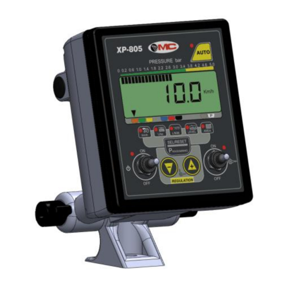
COMPUTER XP805 3.3 Front view The front panel allows the user to view all the data relating to the working cycle. 2 main areas are identified: A. Keyboard area for operation of the main controls and for programming; B. Display area that includes the display and the main lights to display all the information. -
Page 13: Keyboard
COMPUTER XP805 3.3.1 Keyboard FUNCTION Main ON switch Multi-functional select displayed value programming phase SET/RESET ROGRAMMING Multi-functional keys to manually adjust the pump speed and the parameters during programming Switch to enable/disable the output for pump speed adjustment Key with... -
Page 14: Display Area
COMPUTER XP805 3.3.2 Display area 0 0.2 0.6 1.0 3.4 3.8 4.2 4.6 L/ha L/MIN AREA SPEED LIVELLO REF. DESCRIPTION Display to view the values (see ref.4) Triangles indicating the type of selected nozzle Bars indicating the working pressure detected by the specific pressure sensor... -
Page 15: Rear View
COMPUTER XP805 3.4 Rear view The following elements can be found on the back of the computer: A. Buzzer for acoustic signals B. Main connector for wiring connection C. Identification label (lower side) Figure 6. Rear view. Installation and use... -
Page 16: Accessories
COMPUTER XP805 4. Accessories 4.1 Standard accessories Table 4-1. Standard accessories CODE DESCRIPTION 20CAB-XP805-0001 Wiring 4.2 Optional accessories Table 4-2. Optional accessories CODE DESCRIPTION Speed inductive sensor D=18/5mm NAMUR TS L=2.9m with bracket A01G185-K3 Flowmeter 2-20 L/min PL 40-F7 1643 Water pressure transducer 40 BA The pressure sensor is used as an alternative to the flowmeter sensor. -
Page 17: Programming
COMPUTER XP805 5. Programming The computer has 2 different programming levels, one specific for programming the L/ha to be distributed and for selecting the type of nozzle used in the work with a pressure sensor (parameters to be changed often), and one for programming the “machine parameters”... - Page 18 COMPUTER XP805 Programmable range: 0 ÷ 9999 L/Ha Step: 1L/ha Default: 200L/ha Pressing the key will switch to the selection of the nozzle and the following configuration will appear on the display: Letter U will flash. Use the keys to select the type of nozzle: the arrow will indicate the selected nozzle that will also be identified with the letter U followed by the progressive number (U1, U2, U3, U4 ...
-
Page 19: Programming Machine Parameters
SET/RESET this point you can release the key. ROGRAMMING The possible programming modes required by the XP805 Computer will be listed below. Vary the displayed data by pressing the keys separately and then you can confirm it by pressing the key and then going to the next parameter. - Page 20 COMPUTER XP805 Programming the pressure sensor programmable range: 5 ÷ 30 step: 1 default: 10 The "Pr" will flash, thereby indicating the maximum value that can be detected by the pressure sensor used Programming the density of the product used programmable range: 0.50 ÷...
-
Page 21: Practical Example Of Calculation Of Parameter "C" To Be Programmed
COMPUTER XP805 The version numbering method will then be established. 5.3 Practical example of calculation of parameter “C” to be programmed Parameter “C” must be programmed with the number of pulses that the proximity sensor sends to the Computer every 100 linear metres covered by the machine; you must therefore calculate how many references pass in front of the sensor in 100 linear metres. -
Page 22: Automatic Calibration Of Parameter "C" (Recommended)
COMPUTER XP805 N° of wheel revolutions (e.g. 30 ) Starting Finish point point Distance covered (e.g. 60 metres) 100 metres Parameter “C”= x No. of references on the wheel Wheel circumference in meters Figure 7. Practical example of calculation of parameter “C”. -
Page 23: Check The Functionality Of The Speed Sensor
COMPUTER XP805 5.5 Check the functionality of the speed sensor Check the functioning of the speed sensor as follows: Switch on the Computer by setting the relevant switch to <ON>; Press the key repeatedly until Km/h appears on the right side of the display;... -
Page 24: Operation
COMPUTER XP805 6. Operation When switched on, the computer performs a test lasting about 2 seconds, during which: all digital display segments and all LEDs are switched on the buzzer output is activated (if applicable) At the end of the test, the working hours appear on the numeric display for about 2 seconds, during which they can be reset by pressing any key (except for ON/OFF) for about 2 seconds. - Page 25 COMPUTER XP805 AUTO 0 0.2 0.6 1.0 4.2 4.6 L/ha SPEED L/MIN LIVELLO AREA SET/RESET ROGRAMMING REGULATION Pressing Briefly pressing Selected Display range SET/RESET value of the value ROGRAMMING for 2 seconds 0.0 ÷ 51.9 Goes to the next No activation display (L/ha) step 0.1 Km/h...
-
Page 26: Pressure Display Range
COMPUTER XP805 6.1 Pressure display range The computer displays the working pressure by means of the bars on the upper side of the display, according to the following table: Bars ON on the display Corresponding pressure (from the left) ( Bar ) <... -
Page 27: Maintenance
7.1.1 Protection fuses The XP805 computer is fitted with SELF-RESETTING fuses for short-circuit protection on the sensors or on the row closing devices; in the event of a fault, these fuses intervene by disconnecting the power supply to the sensors or to the closing devices: in this case, disconnect the main wiring for a few minutes, eliminate the cause of the fault and connect the wiring to the monitor again. -
Page 28: Maintenance Of The Flowmeter Sensor
COMPUTER XP805 7.2.1 Maintenance of the flowmeter sensor We recommend checking the cleanliness and state of wear of the flowmeter sensor rotor periodically. Proceed as follows to carry out this operation: Unscrew the sensor ring nut completely (Figure 9) and extract the sensor from the main body (there will be some resistance from the O-ring);... - Page 29 COMPUTER XP805 fixing notch fixing notches ring nut Figure 9. If necessary, replace the rotor: with a pair of pliers, gently enlarge the forks and extract the rotor together with the pivot (Figure 11). Enlarge the forks again and insert the new flowmeter kit.
-
Page 30: Troubleshooting
COMPUTER XP805 8. Troubleshooting In the event of a computer malfunction, perform the simple checks below to check whether repairs are needed. If the problem still remains after carrying out the suggested checks, contact your local dealer or MC elettronica Technical Service. -
Page 31: Technical Data
COMPUTER XP805 9. Technical data Power supply voltage 10 - 16 Vdc Maximum current absorption at 16 Vdc 45mA (excluding pump output) Protection rating IP 65 (on the front) Operating temperature range -20 / +70 °C Storage temperature range -25 / +85 °C... - Page 32 Electronic equipment for agriculture www.mcelettronica.it Printed in Italy...
Need help?
Do you have a question about the XP805 and is the answer not in the manual?
Questions and answers