Advertisement
Quick Links
Contents
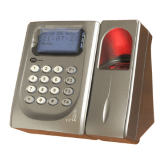
ECL-ACC995-V2
1
Products
2
Installation
A.
Notice
1.Tubing:
The communication wires and power line should NOT be bound in the same conduit or tubing.
Use AWG 22-24 Shielded Twist Pair to avoid star wiring ,CAT 5 cable for TCP/IP connection
2.Wire selection:
3.Power supply:
Don't equip reader and lock with the same power supply. The power for reader may be unstable when the lock is activating, that may make the
reader malfunction.
The standard installation: Door relay and lock use the same power supply, and reader use independent power supply.
Connector Table (1)
P5
3 2 1
Cable:
P1
Wire Application
Wire
Color
Lock Relay
1
Blue White (N.O.)DC24V1Amp
2
Purple White (N.C.)DC24V1Amp
Lock Relay COM
3
White
Door Contact
4
Orange
Exit Switch
5
Purple
Alarm Relay
6
Gray
Power
7
Thick Red
8
Thick Black DC 0V
User Guide
3
Terminal Cables
B.
1
2
P3
P2
P4
8
2
7
1
7
6
6
5
P6
5
4
4
3
4
3
3
2
2
2
1
1
1
P1
8 7 6 5 4 3 2 1
Description
(COM)DC24V1Amp
Negative Trigger Input
Negative Trigger Input
Transistor Output Max. 12V/100mA
(Open Collector Active Low)
DC 12V
COR-ACC995-V2
P1
P2
P3
P4
P5
P6
Use a screwdriver to screw the mounting plate to the wall.
Pull cables ends through the access hole in the mounting plate.
Attach ACC995-V2 to the mounting plate and install screws (supplied) into the holes at the
bottom with the allen key.
Apply power. LED (green) will light up with one beep.
Cable:
P2
Wire Application
Beeper
LED
Door Output
Wiegand
WG Door Contact
WG Exit Switch
Cable:
P3
Wire Application
TCP/IP Output
Cable:
P4
Wire Application
RS-485 for Lift
Controller
4
Tools
5
Optional
Wire
Color
Description
1
Pink
Beeper Output 5V/100mA, Low
2
Yellow
Red LED Output 5V/20mA, Max
3
Brown
Green LED Output 5V/20mA, Max
Transistor Output Max. 12V/100mA
4
Blue White
(Open Collector Active Low)
5
Thin Green Wiegand DAT: 0 Input
6
Thin Blue
Wiegand DAT: 1 Input
7
Orange
Negative Trigger Input
8
Purple
Negative Trigger Input
Wire
Color
Description
1
---
---
2
---
---
3
Orange White Net - TX+
4
Orange
Net - TX-
5
Green White Net - RX+
6
Green
Net - RX-
7
---
---
Wire
Color
Description
1
Thick Green RS-485(B-)
2
Thick Blue RS-485(A+)
V151027
Advertisement

Summary of Contents for Cortex COR-ACC995-V2
- Page 1 COR-ACC995-V2 V151027 Contents ECL-ACC995-V2 Products User Guide Terminal Cables Tools Optional Installation Use a screwdriver to screw the mounting plate to the wall. Pull cables ends through the access hole in the mounting plate. Attach ACC995-V2 to the mounting plate and install screws (supplied) into the holes at the bottom with the allen key.
- Page 2 Biometrics Device Access controller Fingerprint V151027 Connector Table (2) Cable: Wire Application Wire Color Description Anti-Tamper Switch N.C. Orange Yellow N.O. Cable: Wire Application Wire Color Description Power DC 12V Output Security trigger signal Purple Security trigger signal Output Arming Red White Arming Output Duress...
- Page 3 COR-ACC995-V2 V151027 Connect to Electric Strike Connect to Door Contact POWER POWER 12VDC 12VDC Electric Strike Alarm N.O. N.C. N.O. Door Contact Relay Outpot Module N.O. Controller Controller N.C. EXIT POWER POWER 12VDC 12VDC Door Contact Strengthen security with ACC-899...
- Page 4 Biometrics Device Access controller Fingerprint V151027 Programming A. Keyboard Lock/ Unlock Lock/ Unlock Press , and at the same time to lock keyboard. Press again to unlock. B. Entering and Exiting Programming Mode Entering Input 123456 PPPPPP [e.g.] The Default Value= 123456. If already changed the Master Code= 876112, input 876112 →...
- Page 5 COR-ACC995-V2 V151027 F. Adding / Deleting Fingerprint or Finger-Vein Adding Access programming mode → User Setting → Enroll FP → Key in 5-digit user address →1 or 2 different fingers on the sensor lens → Succeeded P.S. The ACC995-V2 need to collect twice for each fingerprint.
- Page 6 Biometrics Device Access controller Fingerprint V151027 M. Anti-pass-back Device enable Access programming mode → Parameters[2] → Anti-pass-back → master controller select [1: Yes] → WG select [1: Yes] Card user enable Access programming mode → Add/ Delete → Antipass Group → Input 5-digit starting user address → Input 5-digit ending user address →...
- Page 7 COR-ACC995-V2 V151027 Software Settings on 701Server Uploading,downloading and deleting fingerprint Uploading fingerprint database to PC database via 701Server First of all,please make sure users have registered their fingerprints to the device. 1.Select node number of the device. 2.Click"Read". 3.Setting "User Range".
- Page 8 Biometrics Device Access controller Fingerprint V151027 IP Setting Open your Web Browser and input factory default IP address: http://192.168.1.127 If the IP address of ACC995-V2 has changed We must enter the new IP address. Page menu Monitor the on-line computer IP Setting Change the Log-in information Current State...
Need help?
Do you have a question about the COR-ACC995-V2 and is the answer not in the manual?
Questions and answers