Table of Contents
Advertisement
Quick Links
Users Guide:
Kantronics
3115 W. 6
th
St., Suite A
Lawrence, Kansas 66049
Orders / Inquiries
Service / Technical Support
MT1200 and MT1200G
Introduction,
Getting Started,
Modes of Operation,
Command Reference, and
Hardware Specifications
(785) 842-7745
FAX (785) 842-2031
e-mail: sales@kantronics.com
website: www.kantronics.com
(785) 842-4476 (8 AM to 12 noon and 1 PM to 5 PM Central Time, M-F)
FAX (785) 842-2031
e-mail: service@kantronics.com
Advertisement
Table of Contents

Related Manuals for Kantronics MT1200

Summary of Contents for Kantronics MT1200
- Page 1 MT1200 and MT1200G Users Guide: Introduction, Getting Started, Modes of Operation, Command Reference, and Hardware Specifications Kantronics 3115 W. 6 St., Suite A Lawrence, Kansas 66049 Orders / Inquiries (785) 842-7745 FAX (785) 842-2031 e-mail: sales@kantronics.com website: www.kantronics.com Service / Technical Support...
-
Page 3: Revisions
REVISIONS Revision Date Description REV- 2006-12-29 Release version REV-B 2007-03-06 Corrections, updates, additions... - Page 4 The MT1200 is manufactured in the U.S.A. © Copyright 2006 by Kantronics Co., Inc. All Rights Reserved. Contents of this publication or the firmware within the MT1200 may not be reproduced in any form without the written permission of the copyright owner.
-
Page 5: Kantronics Warranty Registration
Kantronics Warranty Registration Please take the time to fill out the warranty registration form (or a copy of the form) and mail it to Kantronics, including a copy of your sales receipt, to register your purchase. Kantronics must receive warranty registration within 60 days of purchase of the Kantronics MT1200 to be valid. -
Page 6: Important
1. License. In consideration of payment of the License Fee, which is included in the price of the product, the Licensee (you) is granted by the Licensor (Kantronics Company, Inc. - Kantronics) a non-exclusive right to use the SOFTWARE and associated documentation. - Page 7 (c)(1)(ii) of the Rights in Technical Data and Computer SOFTWARE clause of DFARS 252.227-7013. Kantronics may in its sole discretion, provide you with upgrades of the SOFTWARE and/or Documentation if you have provided Kantronics your completed Warranty registration with a copy of your receipt showing the amount you paid.
-
Page 9: Table Of Contents
Installing Your MT1200(G)..................................19 The MT1200......................................19 Connect Your MT1200 to a Power Source............................20 Connect your MT1200 to Your Computer.............................20 Installing the RS232 Cable................................23 Cabling an external GPS receiver to an MT1200 ..........................24 Alternate GPS Input...................................25 Configure Your MT1200..................................26 HyperTerminal....................................26 AUTOBAUD.....................................27 Setting Basic Communication Parameters............................28 Documentation Conventions..................................28... - Page 10 Assembly and Disassembly................................130 Hard Reset/Self-Test....................................130 Bios Load......................................132 Calibration/Equalization..................................132 Drive level......................................133 Equalization.....................................133 Microprocessor Watchdog Timer................................133 A/D Sensor Inputs....................................134 MT1200 Jumpers....................................135 Jumper Locations.....................................135 Jumper Descriptions..................................136 Appendix C: In Case of Difficulty................................137 MT1200 Does Not “Sign-On” to Computer............................137 You Are Unable to Make a “Connect”..............................137...
- Page 11 Cannot Transmit....................................138 Cannot Return to Command Mode..............................138 Appendix D: Additional Information...............................139 Specifications.......................................139 Messages from the MT1200................................141 ASCII Chart......................................146 ..........................................146 MT1200 Parts List....................................147 MT1200 Parts Layout..................................148...
-
Page 12: Limited Warranty
3. EXCLUSIVE REMEDY. Repair or replacement of the Applicable Product, as provided herein, is the sole remedy available to you against Kantronics, and in no event will Kantronics be responsible for any other liability or damages or for... - Page 13 Applicable Product; to broken or cracked cabinets; to any accessory not supplied by Kantronics which is used with the Applicable Product; to any product that has been subject to misuse abuse or overvoltage; to any product that has been modified by non-Kantronics personnel unless specifically authorized in writing by Kantronics;...
- Page 14 If the dealer is unable to assist you, contact Kantronics Co., Inc., by mail at 3115 W 6th Street, Suite A, Lawrence, Kansas 66049 USA; by fax at 785-842-2031; or by phone at our Service / Technical Support number 785-842-4476 (Hours: 8:00 a.m.
-
Page 15: Return/Repair Procedures
It may be useful to perform a “Hard Reset”. (See Hard Reset section.) If service or repairs still appear necessary after you have checked the items listed above, it may be wise to call, fax, e-mail or write Kantronics to determine if the problem can be solved without returning the unit. - Page 16 Consult the limited warranty policy in this manual for the service provisions offered by Kantronics at no charge. This warranty is considered to be in force only when the customer has submitted his completed warranty registration within 60 days of purchase, and when the stipulations of the warranty have been met.
-
Page 17: International Returns
In case of unit problems, first contact the dealer from whom you purchased the product. If you must return a Kantronics product to us, please observe the steps outlined below. It will save you, the customer, and Kantronics unnecessary difficulties and expense. - Page 18 To be eligible for repair under warranty, we must have a record that you sent your Warranty Registration form and proof of purchase to Kantronics, and the item(s) must still be within the warranty period at the time the return is authorized.
-
Page 19: Radio Frequency Interference Statement
Radio Frequency Interference Statement Note 1: This equipment has been tested and found to comply with the limits for a Class B digital device, pursuant to Part 15 of the FCC Rules. These limits are designed to provide reasonable protection against harmful interference in a residential installation. This equipment generates, uses and can radiate radio frequency energy and, if not installed and used in accordance with the instructions, may cause harmful interference to radio communications. -
Page 20: Rfi Suppression
RFI Suppression In moving to the world of digital communications via computers, a new dimension of RFI may be encountered. In spite of the equipment manufacturers’ diligence, each new piece of electronic equipment will react differently in each separate environment. Every amateur station will have its own unique layout, equipment variation, and antenna installations. - Page 21 This page left blank intentionally...
- Page 22 This page left blank intentionally...
-
Page 23: Welcome
♦ Kit of parts to use in assembling cabling Male DSUB-9 connector for radio port • Metalized DSUB-9 back shell with hardware • 3 foot (0.91 m) piece of 5-conductor shielded cable to connect the MT1200 to • your radio dc power connector •... -
Page 24: Additional Parts For Your Packet Radio Station
MT1200 reports when it is powered on. Additional Parts for Your Packet Radio Station In addition to your MT1200 unit, you will need the following parts to set up your packet radio station: ♦ An FM transceiver ♦... -
Page 26: Uses Of Your Mt1200
Uses of Your MT1200 The MT1200 is designed for use as a stand-alone device, once it has been configured appropriately, along with a transmitter or transceiver for sending GPS position reports, and/or I/O telemetry data reports. It can also be used as a regular TNC for packet communication with other packet stations (with or without the GPS option). -
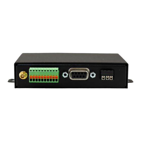
Page 27: Installing Your Mt1200(G)
• some knowledge of operating a packet radio station Installing Your MT1200(G) The MT1200 As shown below, the back of the unit has connectors to connect the MT1200 to your transceiver, a power source, a GPS antenna (on MT1200G only), and telemetry analog and digital inputs:... -
Page 28: Connect Your Mt1200 To A Power Source
Connect Your MT1200 to a Power Source Shown on the right side of the Back Panel, is the power connection to the MT1200. The supplied power plug will require a small flat blade screwdriver to attach the power supply wires. - Page 29 Specify that one connector be a male DSUB-9 connector (to connect to your • MT1200’ female “Computer” port) and the other connector be a female DSUB-9 or DSUB-25 connector (depending upon whether your computer’s serial (COM) port has a male DSUB-9 or male DSUB-25 connector) Making a Serial Cable This section is for those making your own cable instead of purchasing one.
- Page 30 25-pin connector or a 9-pin connector, and on how many wires are in the cable (you only need 5 wires connected for MT1200 operations, but you may connect more wires to use the cable for other purposes).
-
Page 31: Installing The Rs232 Cable
If you are not using a PC compatible computer, the wiring required between your computer and your MT1200 is the same wiring you would use for a “Hayes” type external telephone modem. This cable should be available from your computer dealer. -
Page 32: Cabling An External Gps Receiver To An Mt1200
The data output pin may be identified as “NMEA+” by some GPS vendors; this is the line that supplies the NMEA sentences to your TNC. Enable GPS input to the DB9 serial port by setting ABAUD in the MT1200 to match •... -
Page 33: Alternate Gps Input
Also, make sure this pin will accept an RS232 signal (+ and – voltages). Alternate GPS Input In the MT1200, an alternate input for GPS data is available. This input is pin 2 on the MT1200 “Radio” port, and is enabled with the command GPSPORT. A data signal ground is also required, which is pin 6 or pin 9 on the “Radio”... -
Page 34: Configure Your Mt1200
Add Program, Add Windows Component from the Control Panel to install it. Click HyperTerminal from the Accessories menu. HyperTerminal will open with a window asking for a name for a new connection. Enter “MT1200 9600”. Pick a different icon if you want, then click OK. -
Page 35: Autobaud
HyperTerminal screen already set up for the MT1200. Later you may wish to change the baud or com port you are using with the MT1200. Before you can do that in HyperTerminal, you will first have to tell HyperTerminal to “disconnect”;... -
Page 36: Setting Basic Communication Parameters
➔ Hint: Do not confuse the MT1200’ baud for serial communication on the computer port with the MT1200’ 1200-baud for communicating using the radio port, which is connected by a custom-wired cabling to a transceiver. Setting Basic Communication Parameters There are several MT1200 settings in addition to ABAUD (baud) and MYCALL... -
Page 37: Trouble-Shooting Difficulties In Communicating
COM port setting in HyperTerminal and try again. Another possibility is that the MT1200 has already been programmed with a different baud than the one set in the terminal program. You can try changing the baud in the terminal program, or you can use the self-test jumper (J11) to erase the current settings in the MT1200, forcing the MT1200 to try its Autobaud routine. - Page 38 See the TNC documentation for instructions on how to determine what Interface Mode your TNC is in currently and how to change it to the Interface Mode you want.
-
Page 39: Connect The Mt1200 To Your Transceiver
There are many different models of transceivers, each with their own exact requirements for how they are to be connected to devices such as a MT1200. While the following examples will help, you will need to refer to your transceiver documentation (or transceiver dealer) for exact instructions on which connections you need to make as you wire your transceiver cable assembly. - Page 40 Kantronics is not likely to have pin assignments for specific transceiver models. The following diagrams, used for example only, show wiring connections between the male connector for the MT1200’ “Radio” port and transceivers (including HTs) from three major manufacturers: Yaesu, Icom, and Kenwood.
- Page 44 5, receive audio on the MT1200’ DSUB-9 “Radio” port), • identify and make a note of the connector to your external speaker plug (which will be wired to pin 6, one of the ground pins on the MT1200’ DSUB-9 “Radio” port).
- Page 45 Hint: You may find it easier to wire the male DSUB-9 connector if you first connect it to the MT1200 and use the MT1200 as a test fixture. This may also keep the male pins straight if you apply too much heat and soften the plastic in the male connector.
- Page 46 11. If your radio is equipped with a single metal connector, then this same cable with connector attachment technique should be used. Otherwise follow the wiring directions that follow. Wiring between your Transceiver Microphone and your MT1200: Follow the notes taken above and wire the cable assembly in the following order: Step 1.
-
Page 47: Connecting Your Transceiver Cable Assembly
Step 4. Secure the male DSUB-9 connector on the cable to the female DSUB-9 connector on the MT1200’ “Radio” port, by screwing the two long, half- threaded screws into the threaded nuts on each side of the MT1200’ “Radio” port,... -
Page 48: Adjusting The Receive Volume Of Your Transceiver
If you connected to a fixed level (unsquelched) receive audio from the radio, the receive LED on the MT1200 may remain on all of the time. In this case, set the parameter CD to SOFTWARE. Then, the receive LED will not light until valid packets are heard. (see CD... - Page 49 (CAL) command. Previous models used a set of jumpers and an analog potentiometer (pot) to set this level. With the MT1200, no jumpers are used, just a command. You should adjust the drive level to provide about 3 to 3.5 kHz of deviation with your radio.
-
Page 50: Getting Started
Reading this chapter (or just skimming the material, if you are already familiar with the topics) will also help you use the following chapters on different modes of use of the MT1200, the “Command Reference” chapter, and any appendices that are relevant to your needs. -
Page 51: The Front Panel Of The Mt1200
The Front Panel of the MT1200 You have already used the POWER switch on the MT1200 to turn power on and off. This is a good time to get familiar with all the indicators on the front panel of the MT1200. -
Page 52: Beginning A Session
DUPLICATION PROHIBITED WITHOUT PERMISSION OF KANTRONICS. cmd: The last line of this message (“cmd:”) is the MT1200’ report that it is in “Command” mode, which means that it is now expecting information from HyperTerminal to be commands for it (the MT1200) to interpret and carry out. Before learning about the... -
Page 53: Check Your Mt1200' Version Number And Id
COMMAND mode, enter “<Ctrl+C> three times, with a pause of less than one second between each entry. Check Your MT1200’ Version Number and ID To check your MT1200’ version number and ID all you need to do is ask to see the current setting of the command called VERSION: Step 1. -
Page 54: View Current Values Of Parameters
To confirm that the current value(s) is what you want, enter the name of the command and press ENTER. The MT1200 will send a message consisting of the name of the command and the current value(s) of its parameter(s) for display on your monitor. -
Page 55: Monitor Communications From Nearby Stations
Let’s say that you decide to connect to KBØNYK. The steps needed are as follows: Step 1. First, be sure you have the MT1200 in command mode. To do this, type <Ctrl+C> and then press return. You should see a command prompt (cmd:). - Page 56 • using network nodes, and • beaconing GPS data. This concludes a quick tour of basic uses of your MT1200. With just these basics, you can do a lot, but you have a great deal more power if you want to explore the full possibilities.
-
Page 57: Modes Of Operation
Modes of Operation This chapter covers the major ways in which you may use your MT1200 TNC. For details on particular commands, see the “Command Reference” chapter. Packet Mode Protocol for Amateur Packet Radio: AX.25 The mode commonly called PACKET is defined by the protocol called AX.25. The details of the inner workings can be found in a book titled “AX.25 Amateur Packet-Radio... -
Page 58: Monitoring And Calling Cq
Therefore the Connected Mode, barring impossible conditions, assures that the station you are connected to will receive everything you say, and in the order you say it. In the Unproto Mode, when your TNC sends a packet, no acknowledgment is expected and no retries are attempted. - Page 59 Which way you implement this depends on the capabilities of your computer communications program and personal preference. The cable between your computer and TNC must also be wired appropriately. Software Flow Control Software flow control sends special characters on the TXD and RXD lines of the RS232 cable.
-
Page 60: Convers Mode Vs. Transparent Mode
high as long as it can receive data and pulls it low to tell the TNC to stop sending data. The TNC always uses hardware flow control, so only wire the RTS and CTS pins if your computer program is also using hardware flow control. HyperTerminal uses hardware flow control in its default settings, but some communication software does not. - Page 61 followed precisely. This example assumes the COMMAND character is <Ctrl+C> and CMDTIME is 1 second: • Wait at least 1 second since the last character was sent from the computer to the • Type a <Ctrl+C> • Within 1 second type a second <Ctrl+C> •...
-
Page 62: Linesub Mode
Linesub mode LINESUB Protocol Description The LSUB mode of operation provides a method of transmitting-and receiving raw ASCII data via a radio. Data is sent and received in a totally transparent fashion, allowing all ASCII characters to be utilized (hex 00 through hex FF). There is no addressing, error-detection or automatic retransmission of the data. -
Page 63: Tup Mode (Transparent Unproto Packet)
and turn the unit off and then back on. Be aware that there is no data flow control. Exiting LSUB Mode If you want to exit LSUB mode to "fine tune" parameter settings (or for any other reason), the Command mode of the modem can be regained by using the transparent data escape sequence, i.e., by sending a series of three control-Cs (unless a different control character has been defined). - Page 64 be set to the same value at all sites. It is the responsibility of the host system to insure that additional data is not transmitted until sufficient time has elapsed to allow data to travel to the last digipeater and the response, if any, to travel back to the host. Note that the automatic "Time to Live"...
-
Page 65: Poll Mode
Exiting TUP Mode If you want to exit the TUP mode to "fine tune" parameter settings (or for any other reason), the Command mode of the modem can be regained by using the transparent data escape sequence, i.e., by sending a series of three control-Cs (unless a different control character for COMMAND has been defined). - Page 66 Control Site Transmit Format - All data sent to the Control modem via the RS232 serial port must begin with a POLLID (four digit remote address between 0001-9999) and be followed immediately by the poll data. The data sent by the application to the Control modem must contain less than PACLEN bytes.
- Page 67 CAUTION: MASTER (Control Site) operation will be unusable if PACLEN is exceeded since each packet of data sent MUST begin with a Slave (Remote Site) POLLID (0001- 9999). Remote transmission may exceed the setting of PACLEN since each packet transmitted from the Remote will contain the proper POLLID. If fragmentation of data occurs, the application program is responsible for reconstructing the data.
-
Page 68: Modem Mode
Exiting POLL Mode If you want to exit POLL mode to "fine tune" parameter settings (or for any other reasons), the command mode of the modem can be regained as follows: If CONMODE = CONV Enter: 0000QUIT<cr> (NOTE: QUIT MUST BE IN UPPER CASE) If CONMODE = TRANS Use the transparent data escape sequence, i.e., send a series of three control-Cs (unless a different control character has been defined). -
Page 69: Kiss Mode
The NWS feeds a constant stream of weather information (@ 1200,8,N,1), from around the world, to a satellite orbiting the Earth. Many cities are coming on line now to capture this stream and rebroadcast it on fixed VHF commercial FM frequencies just above the 2-meter ham band. -
Page 70: Xkiss (Extended Kiss) Mode
3. Press and HOLD the ALT key. Type the numbers 192 from the numeric KEYPAD. Release the ALT key. If the terminal program you are using sent all those characters, the MT1200 will exit KISS mode. References on KISS Mode Karn, P.: “TCP/IP: A Proposal for Amateur Packet Radio Levels 3 and 4", pp. -
Page 71: Remote Access
Remote Access You can connect to your MT1200 from a remote station and change values of its parameters. This allows you to add or delete stations from the LLIST, change the MYCALL or any other command setting, read the analog inputs, set control line outputs, and so on, all remotely. - Page 72 For example, if you give the command DISPLAY, there will be no display content. There is too much data to pass through the remote connection from the MT1200. Any single command can be queried, and get a display of its current setting.
-
Page 73: Gps Beacon
The MT1200G includes a GPS device inside. This GPS device is a small module, made by Trimble. The MT1200 does not include a GPS inside. To utilize GPS functions with the MT1200, an external GPS receiver is required. Unlike other, more full featured Kantronics TNCs, the MT1200 has one GPS buffer and beacon, which transmits text as defined by its GTEXT command. -
Page 74: Other Gps Beacon Features
GTEXT $GGA$$CHKSUM$ <CR> Each variable name must be enclosed in $ characters and entered in CAPITAL letters. The NMEA strings usually begin with a $ also, and that is entered with the variable string. The entry above designates the $GPGGA sentence with a checksum. A maximum of 126 characters can be entered in the GTEXT command. - Page 75 GPS beacon to be transmitted. The setting APPEND is used in combination with pin 7 on the radio port of the MT1200. That input should be a connection to the PTT line of your transceiver, along with your microphone.
-
Page 76: Gps Command Summary
This is an immediate command. When entered with a callsign, a special “PING” packet will be sent to the specified callsign. If that TNC is another MT1200, it will send a PING response packet with its current GPS information (as specified by the GTEXT setting). - Page 77 Sproul, Keith, WU2Z, “MacAPRS”, 13th ARRL Digital Communications Conference Proceedings, 1994. Technical Information Collins, J., et al., GPS Theory and Practice, Second Edition, Springer-Verlag, 1993. Etherington, Michael, “FM subcarrier network extends differential GPS nationwide”, Mobile Radio Technology, February 1994. Kaplan, Elliot, “The global positioning system (GPS)”, Communications Quarterly, Summer 1994.
-
Page 78: Other Modes Of Operation
CTRL command to control selected output lines in • the remote TNC (up to two output lines in the MT1200). Each of these output lines can be set to OPEN (i.e., OFF) or GROUNDED (i.e., ON) by the CTRL command. - Page 79 You can also use the ANALOG, IO, and/or CTRL commands, from your local terminal, to carry out sensing and control functions at a local Kantronics TNC. The following diagram illustrates the use of two Kantronics TNC/radio stations for remote control and sensing. These operations could be carried out manually or via a terminal program running in the computer in the central TNC station.
-
Page 80: Command Reference
Default values are stored in the EPROM section of the MT1200 microprocessor. If you change any setting or value, it will be stored automatically within a few seconds, and will be the value used at future power-on. -
Page 81: Parameter Types
If commands have parameters, default values are shown on the line below the command definition. Some MT1200 commands take effect immediately, so they are called “immediate” commands (e.g., K means “switch to CONVERSE mode"). This will be stated on the second line. - Page 82 n ($00 - $FF) Special functions: Some parameters are used to control special functions, such as specifying the character to use to enter the Command mode from the Convers mode or specifying the character to use for “backslash”. Possible values and default values for these parameters are shown in HEX format.
-
Page 83: Entering Commands
PASS character. The string ends when you type a (non-passed) carriage return. Entering Commands To enter a command, the MT1200 needs to be in COMMAND Communication Mode (as opposed to CONVERS or TRANS communication mode). The prompt for Command Mode is: cmd: Hint: Once you go into Packet Convers Mode a <Ctrl+C>... - Page 84 When you are at the Command Mode prompt, you enter a command for the MT1200 by typing the command name (in upper or lower case) and any required and optional parameter values (argument settings or values). The command name and each parameter value must be separated from each other by at least one space.
-
Page 85: Mt1200 Commands
The parameter n sets the baud used for input and output through the serial RS232 port of the MT1200 to the computer. If 0 is used, the MT1200 will run an autobaud routine upon power-up. This routine looks for an asterisk (*) character from the attached computer to set the ABAUD parameter. - Page 86 ANALOG immediate Entering the ANALOG command returns a string of 2 values, based on the voltage readings from A-to-D input lines, located on pins 7 and 9 of the Telemetry jack. At any given time, each of the 2 A-to-D lines can have a voltage value somewhere in the range of 0 –...
- Page 87 AX25L2V2 {ON | OFF} default ON This command provides compatibility with all known packet units implementing AX.25 protocol. When ON, Level 2 Version 2 protocol is implemented and the TNC will automatically adapt to whichever version the connecting station is using. When OFF, Level 2 Version 1 is implemented.
- Page 88 Each increment specifies 10 millisecond intervals. This value may be used to improve channel utilization when audio repeaters with a hang time greater than 10 ms are used. If the repeater squelch tail is long, it is not necessary to wait for AXDELAY after keying the transmitter if the repeater is still transmitting.
- Page 89 If BREAK is ON, a modem break sent from the terminal causes a return to Command Mode from Converse or Transparent Mode. See also: COMMAND BTEXT text (0 - 128 characters) default (blank) BTEXT specifies the content of the data portion of the beacon packet. Any combination of characters and spaces may be used with a maximum length of 128.
- Page 90 ➔ Note that entering callsign1>callsign2 or callsign1<>callsign2 counts as two of the 10 maximum allowed callsigns. CALIBRAT immediate The CALIBRATE command can be used to generate a signal which may be used as an aid in adjusting transmit audio drive level to your transceiver, or can be used to detemine whether an equalization adjustment is required.
- Page 91 CD {INTERNAL | EXTERNAL | SOFTWARE} default INTERNAL The CD command selects which carrier detect method will be used. When set to INTERNAL, the TNC will detect a signal present on the channel, using an energy type carrier detect, allowing shared voice and data on the same channel. Any receive audio will trigger carrier detect.
- Page 92 To exit Transparent mode, you need to wait at least CMDTIME since the last data character was sent to the MT1200. Then you need to enter the COMMAND character (e.g., <Ctrl+C>)) three times, with a wait of LESS THAN the value of CMDTIME...
- Page 93 CMSG {ON | OFF | DISC} default OFF When OFF, the custom connect text stored in CTEXT will not be sent to the connecting station upon receiving a connect request. When ON, the custom CTEXT string will be sent. When CMSG is set to DISC, the custom CTEXT string will be sent to the connecting station, and then your TNC will disconnect from that station.
- Page 94 CONMODE {CONVERS | TRANS} default CONVERS This command controls the mode the TNC will be placed in AUTOMATICALLY after a connect if NOMODE is OFF. The connect may result either from a connect request received or a connect request originated by a CONNECT command. If the TNC is already in Convers or Transparent Mode when the connection is completed, the mode will not be changed.
- Page 95 CONOK {ON | OFF} default ON When ON, connect requests from other TNCs will be automatically acknowledged and a <UA> packet will be sent. The standard connect message will be output to the terminal and the mode specified by CONMODE will be entered if you are not connected to another station and NOMODE is OFF.
- Page 96 CRSUP {ON | OFF} default OFF This command was added to the first multi-mode TNCs (such as the Kantronics UTU and KAM) to accommodate the practice by radio teletype (RTTY) operators of adding an extra carriage return (CR) at the end of each line (i.e., CR, CR, linefeed (LF) ). This was done to give the carriage of the old mechanical teletypes time to return across the page.
- Page 97 See also: MYCALLl, CWIDTEXT CWIDTEXT text (0-15 characters) default DE mycall This command sets the text to be transmitted when the MT1200 performs an automatic CWID. The text will be transmitted periodically as set by the CWID command. See also: CWID...
- Page 98 DAYSTR text default yyyy-mm-dd hh:mm:ss The DAYSTR command is used to set the FORMAT of your date/time display. DO NOT enter an actual date or time, simply enter the form of the display you would like, using the lower case letters m, d, h, y, and s as described below. The format you enter is used for displayed time stamps.
- Page 99 (in error) to attempt to supply an actual date and time. If this is not the case, fix the problem and see if time and date displays work correctly. If the MT1200 was ordered with the internal GPS installed, the Daytime will automatically be set based on GPS time, upon valid GPS fix.
- Page 100 TNC operations and does not interfere with normal connected operation of the station. To disable digipeat operations (via MYCALL, or MYALIAS), set this command to OFF. If UIONLY is selected, the MT1200 will digipeat UI frames only. Connect type packets will be ignored. See also: HID, MYALIAS, MYCALL...
- Page 101 MT1200 moves to the disconnected state. Entering a second Disconnect command before RETRY has expired will result in an immediate disconnect on your end, but may leave the other station thinking it is still connected to you. Disconnect messages are not displayed when the TNC is in Transparent Mode.
- Page 102 up time (TXDELAY). This feature is made available to help alleviate the drastic reduction of throughput, which occurs on a channel when digipeated packets suffer collisions. Digipeated packets are not retried by the digipeater but must be restarted by the originating station. If all stations specify DWAIT, and the right value is chosen, the digipeater will capture the frequency every time it has data to send since digipeated packets are sent without this delay.
- Page 103 channel traffic, which includes binary file transfers, or higher level protocols (networks talking to each other). Control characters, which may be embedded in those packets, can have strange and unpredictable effects on the monitoring TNC. All control characters except carriage return ($0D) and line feed ($0A) will be filtered. This command DOES NOT affect receipt of control characters in packets received from a “connected”...
- Page 104 If the option APPEND is included, and the PTT line between the microphone and radio is also connected to pin 7 on the MT1200 radio port, a GPS beacon will be transmitted upon release of the microphone PTT.
- Page 105 See also: GBEACON GPS OFF | ON default OFF This command is used to enable/disable the internal GPS module in the MT1200G. Note: this command is not available in the MT1200. GSAVE n |GBEACON (n = 0 – 60 s) default 0 This command sets an interval, at which to save a copy of GPS data in the GPS data log.
- Page 106 Entering the word “HELP” alone, without any argument, will generate a display listing all commands available in the MT1200. When the name of a command is entered also (e.g., HELP CONVERS), a brief description of that command will be displayed.
- Page 107 IGNITION {ON | OFF} default OFF When set to ON, the MT1200 will not power on unless the IGNITION input is active. The Ignition input is the middle pin of the Power Jack. It should be connected to a line in the vehical that is active (has voltage) when the Ignition of the vehicle is ON.
- Page 108 (see the LINESUB mode section of this manual). When INTFACE is set to MODEM, the MT1200 mirrors at the RS232 port @ 1200 baud what it receives at the radio port (for more information, see the “modem mode” in the Modes of Operation chapter).
- Page 109 TNC. This case translation is disabled in Packet Transparent Mode. LEDS {ON | OFF} default ON To conserve power, disable the indicators (LEDS) on the front-panel of the MT1200 by setting LEDS to OFF. LFADD {ON | OFF} default OFF When ON, a line-feed will be appended to every carriage return received from the keyboard before being transmitted.
- Page 110 LLIST [ON | OFF] [NONE | {+|-}callsign | callsign1,callsign2...] default OFF LLIST is used to determine which stations (callsigns) may NOT use your station for ANY purpose, including digipeating. When LLIST is ON, the TNC will NOT recognize those packets received with any callsign that appears in the LLIST’s (lid) list of callsigns. In addition, when LLIST is ON, you will not be able to connect to any station that is on that list.
- Page 111 When entered with the a specific date and time, all records stored since that time will be displayed. When entered with a date range (from date and time, to date and time), all records stored within that range will be displayed. Note: the LOG function is not available in some units.
- Page 112 MCOM {ON | OFF} default OFF Supervisory (control) packets are not monitored unless MCOM is set ON and MON is ON. In addition if your station is connected, control packets are not monitored unless MCON is also ON. Control packets, when displayed, are distinguished from information packets by the “<>”...
- Page 113 When ON, the headers are displayed for all monitored packets. When OFF, headers are not displayed and only data is output to the terminal. Since only I and UI frames have data, only these frames are displayed. ➔ To avoid confusion when MHEADER is OFF, use BUDLIST to restrict the monitored data.
- Page 114 <RRr> Receive Ready, r = received sequence number In addition, the following bracketed information will be added to the Information packets as appropriate: <Isr> Information frame (connected); s = send sequence number, r = received sequence number See also: AX25L2V2, MCOM, MONITOR For more information, see the book AX.25 Amateur Packet-Radio Link-Layer Protocol Version 2.0 October 1984, which may be obtained from the ARRL.
- Page 115 When ON, the MT1200 will display transmitted packets as monitored data on your terminal. Repeated packets will be displayed as they are sent over the radio. The frames to be displayed will be controlled by the MONITOR, MCOM, MCON, and MRESP commands, and will obey the settings of TRACE, MSTAMP, HEADERLN, 8BITCONV and FILTER commands.
- Page 116 This command sets the KISS address of the radio port in the MT1200. A KISS frame with the upper nibble of the command byte set to this value will address this MT1200. See also: INTFACE, KISS operation section MYREMOTE xxxxxx-n...
- Page 117 This command specifies the maximum length of the data portion of a packet. The TNC will automatically send a packet when the number of input bytes reaches n. This value is used in both Convers and Transparent Modes. A value of 0 means 256 bytes. See also: MAXFRAME PACTIME [EVERY | AFTER] n (n = 0 - 255)
- Page 118 address field as well as the data field and display the packet as specified by other commands such as MONITOR. ➔ When PASSALL is OFF, packets will be displayed only if the CRC (error checking) is correct and as specified by other commands such as MONITOR. PERSIST n (n = 0 - 255) default 63...
- Page 119 PMODE {CMD | CONV | TRANS} default CMD The PMODE command controls the mode your MT1200 will be in when it is first powered up or reset. When set to CMD, the MT1200 will produce a sign-on message followed by the command prompt. When set to CONV, the unit will be in the Convers Mode.
- Page 120 connect a temperature sensor to an A/D pin, which outputs 0-3.3 V for temperatures of –40 to 100, set the range for that input to –40 to 100.0. A pressure sensor that gives 0-3 V for 1 PSI would use a range of 0 to 1.25. See also: ANALOG, TELEMETRY REDISPLA n (n = $00 - $FF)
- Page 121 See also: INTFACE, MYREMOTE, RESTORE RESTORE immediate When the command RESTORE is given, the MT1200 will revert to its factory default settings, and will start to its AUTOBAUD routine. See also: RESET RETRY n (n = 0 - 15) default 10 This command specifies the number of packet retries.
- Page 122 This is an immediate command, which sends the “text” string to the device attached to the RS232 port. It is intended to allow a remote SYSOP (connected to the MT1200 through its MYREMOTE callsign) to send a string of data to output from the serial port of the MT1200, to a device attached to its serial port.
- Page 123 Note that case is significant and spaces are considered valid characters. If you fail to properly decode the password, the remote MT1200 will send three new lines of numbers. You will be given a maximum of three attempts to properly decode the password string.
- Page 124 START n (n = $00 - $FF) default $11 <Ctrl+Q> This command specifies the character sent by the computer to the TNC to restart output from the TNC. If set to $00 only hardware flow control will be used. For software flow control, set this parameter to the character the computer will send to restart data flow.
- Page 125 SUPLIST [ON|OFF] [NONE | {+|-}call | call1,call2,..] where call={callsign | {<|>}callsign | callsign{>|<>}callsign} default OFF NONE SUPLIST is used to determine which received packets will not be displayed, i.e. suppressed. When OFF or NONE, SUPLIST will not prevent the display of packets, even if it has callsigns in its list.
- Page 126 The values need to be separated by commas as they are entered (as shown). Also as shown, spaces between values are not necessary—but entering spaces after the commas is OK. Once carrier detect is active, the counter must drop to 0 before carrier detect is again made false.
- Page 127 This command displays the current temperature from the on-board sensor inside the MT1200. TRACE {ON | OFF} default OFF When ON, all received frames are displayed in their entirety, in hexadecimal, including all header information. All packets, which are eligible for monitoring also, will be displayed in normal text.
- Page 128 See also: TRANS, TXFLOW, XFLOW TRIES [n] (n = 0 - 15) The TRIES command will display and optionally set the number of attempts, which have been made to re-send a packet which failed to reach its destination. For instance, if RETRY is set to 10, TRIES will show how many attempts have already been made to pass the data.
- Page 129 MONITOR ON. If you are connected, you must also set MCON ON. See also: BEACON, ID, MONITOR, MRPT, XMITOK VERSION immediate This command causes the MT1200 to display its current version number along with the name of the unit.
- Page 130 VOLTAGE immediate This command causes the display of the current power supply voltage input to the MT1200. XFLOW {ON | OFF} default ON When ON software flow control will be implemented according to the settings of START, STOP, XON, XOFF. For normal software flow control set XFLOW ON, START $11, STOP $13, XON $11, XOFF $13.
- Page 131 XMITLVL n (n = 0-502) default 100 This command may be used to set the modem drive level. You may find it more convenient to use the CAL command in that it allows you to continuously adjust drive level by holding down the + or – key while in calibrate mode. The voltage range set by the XMITLVL command is from 1 mV to 4 V p-p.
-
Page 132: Appendix A: Advanced Installation
Appendix A: Advanced Installation This appendix gives you additional information on installation and configuration beyond that given in the chapter on “Installing your MT1200”. We assume you have already read that chapter. Precautions The MT1200 is grounded through its connections to your transceiver, computer, and power supply. -
Page 133: Cable Wiring
RXD - RECEIVE DATA: This line carries the data from the MT1200 to your computer. RTS - REQUEST TO SEND: The MT1200 checks this line to see if it is permitted to send data to your computer. This line is controlled by your computer software program,... -
Page 134: Software Settings
CTS - CLEAR TO SEND: The MT1200 uses this line to signal your computer when it can no longer accept data from the computer, or to signal that it is again ready to accept data. This pin is used for hardware flow control. -
Page 135: Interfacing Hand-Held Radios
“hardware” transmit inhibit. Pin 3: When the MT1200 needs to key your transmitter, it will apply a ground to this pin. This is an open-drain circuit and requires a positive voltage from your radio (not to exceed 60 V dc or 115 mA). - Page 136 J4 on the center post and the left post (labeled HT) as you face the front of the MT1200. Should you later use a different type radio, this change may need to be reconfigured by placing the J4 jumper on the center post and the right post.
-
Page 137: Optional Connections To Dsub-9 Radio Port
GPS packet upon release of the microphone PTT. Connections to the I/O jack The I/O jack on the MT1200 is a 10-pin terminal block type, socket. Six of the pins are three pairs of optically isolated digital inputs, and two pins are analog inputs. The analog inputs are capable of sensing voltages in the range of 0 to +3.3 V. -
Page 138: Appendix B: Advanced Information
This procedure is performed as follows: 1. Open the MT1200 by removing the two (2) case screws on the sides of the unit and lifting the cover. 2. Locate the Hard Reset jumper (J1). Jumpers are appropriately labeled on the PC... - Page 139 3. Place the jumper plug on both pins. 4. Apply power to the MT1200. 5. Observe the LEDs on the front of the MT1200. Each LED will light in turn, starting with Power, and ending with GPS status. 6. After the LED test, observe on the computer display (your terminal program must be...
-
Page 140: Bios Load
Warning!: If you choose Y to erase the current BIOS but do not then send the BIOS file or if it is not received correctly, the MT1200 will not have a valid BIOS from which to operate, and its only function will be in the loading of a new BIOS. -
Page 141: Drive Level
This can be helpful to check the transmitter deviation with each tone. Equalization. If there is another Kantronics user nearby, you can have that station transmit a calibrate signal from their TNC, and choose the R option in your calibrate mode to measure the status of receive equalization. -
Page 142: A/D Sensor Inputs
A/D Sensor Inputs Two A/D inputs are available to the MT1200 and are used with the Analog command. These inputs can be used to measure dc external voltages from 0 V to 3.3 V dc with up to 8-bit accuracy. -
Page 143: Mt1200 Jumpers
Flash test/Load Note: If your MT1200 was purchased without the internal GPS, and you wish to use data from an external GPS (or other) device, you will need to solder in a jumper connecting the pads at position R27. Then, your device output should be connected to... -
Page 144: Jumper Descriptions
J9: (Flash Test/Load) This two pin jumper is used to test a flash load of the BIOS, or to load a BIOS into the MT1200. When connected and the unit powered on, The option of test loading a BIOS is presented. If Y is chosen, a BIOS file can sent to unit, and a report will be displayed. -
Page 145: Appendix C: In Case Of Difficulty
LED does not illuminate, check to be sure the XMITOK command is turned ON. 2. Observe the radio to determine if it is being switched to the “Transmit” condition. If not, recheck wiring between the MT1200 radio port, PTT pin, and ground on the microphone jack. -
Page 146: Cannot Transmit
CD parameter to SOFTWARE. Cannot Return to Command Mode The single most common cause of this is that you or a program you have run, have left the MT1200 in a different communication mode such as KISS, LINESUB, TUP, or MODEM mode. -
Page 147: Appendix D: Additional Information
Appendix D: Additional Information Specifications Size: 0.95" H x 4.85" W x 3.0" D (2.4 cm H x 12.3 cm W x 7.6 cm D) Weight: 4.8 oz (0.136 kg) Power Requirements: 5 V dc to 16 V dc, 12 V nominal 35 mA (LEDs on, GPS inactive) 65 mA (LEDs on, GPS active, no GPS antenna) 75 mA (LEDs on, GPS active, with GPS antenna) - Page 148 Operational (COCOM) Limits with Internal Trimble Lassen iQ GPS module: Altitude: 18,000 m. Velocity: 515 m/s. Note: either limit may be exceeded, but not both. Performance Specifications of Internal Trimble Lassen iQ GPS Module: General: L1 (1575.42 MHz) frequency, C/A code, 12-channel, continuous tracking receiver.
-
Page 149: Messages From The Mt1200
This message appears on your screen when you enter the Calibrate Mode. It prompts you to press M to generate a MARK tone, R to receive a Kantronics Calibrate signal, S to generate a SPACE tone, T to transmit a Kantronics Calibrate signal, –... - Page 150 *** CONNECTED to call [VIA digi1..digi8] A packet connection has taken place. This can happen by you issuing a connect request or a connect request coming in from a remote station. “call” will be the callsign entered in the remote stations MYCALL and if a path was used it will be shown.
- Page 151 BUDLIST QST,KBØNYK; the NØKN callsign is ignored. KANTRONICS MT1200 VERSION 06228-1.0 SERIAL NUMBER 0000000101 (C) COPYRIGHT 2006 BY KANTRONICS INC. ALL RIGHTS RESERVED. DUPLICATION PROHIBITED WITHOUT PERMISSION OF KANTRONICS. cmd: A message such as this (different for each product, but with this format) appears when the TNC is first turned on and after any soft reset, including changing the MYREMOTE commands, or issuing the RESET command.
- Page 152 PRESS (*) TO SET BAUD You need to press the asterisk (*) key on your keyboard within 2 s of seeing this message. The MT1200’ autobaud routine will then detect what baud your computer is using, so the two devices can communicate.
- Page 153 Whenever one of the parameters is changed, the previous value is usually displayed. Example: at the cmd: enter; AX25 OFF the response will be; AX25L2V2 was ON...
-
Page 154: Ascii Chart
ASCII Chart Ctrl Code Code Code Code “ & ‘ < >... -
Page 155: Mt1200 Parts List
19-22,25, 33-40,46,47 A1C12,13 CAP, 180 pF 5 % NP0 50 V 0603 109-0181-50 Note: the Telemetry plug is not included in the MT1200 package. It must be A1C14,24,28 CAP, 1 µF 10 % X5R 16 V 108-2105-6 ordered separately. A1C23 CAP, 10 µF 10 % 35 V Tant... -
Page 156: Mt1200 Parts Layout
MT1200 Parts Layout Top side... - Page 157 Bottom side...
Need help?
Do you have a question about the MT1200 and is the answer not in the manual?
Questions and answers