Table of Contents
Advertisement
Quick Links
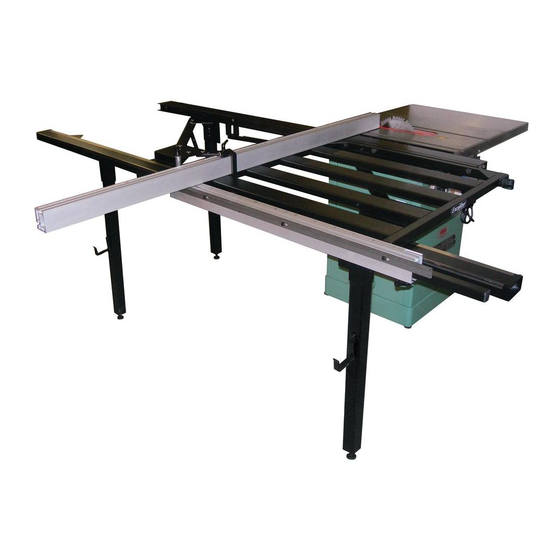
SETUP & OPERATION MANUAL
FEATURES
The table rides on 14 sealed, steel ball
bearing rollers and is supported by archi-
tectural grade heavy-duty steel tubing.
Easy to adjust, extruded aluminum miter
fence for accurate miters from 0° to 45°.
Adaptable to virtually all 10-14" table
saws.
New design sliding quick mount bracket
for added cutting capacity. Cut up to 49"*
with the crosscut fence positioned at the
rear. Crosscut or miter up to 28"* with the
fence at the front of the table.
Quick connect mounting bracket allows
for easy removal of the sliding table from
the saw for users with space/storage limi-
tations.
Positive stop rail and locator pin quickly
sets fence for commonly used miter
angles.
SPECIFICATIONS
WORKING FLOOR SPACE
(FRONT TO REAR)
78" (1980 MM)
WORKING FLOOR SPACE
(TO LEFT OR RIGHT OF SAW)
30" (762 MM)
WIDTH OF SLIDING TABLE
26" (661 MM)
LENGTH OF SLIDING TABLE
30" (762 MM)
DISTANCE IN FRONT OF BLADE
TO CUT AT 90°*
28" (711 mm)
DISTANCE FROM REAR OF BLADE
TO CUT AT 90°*
49" (1245 MM)
LENGTH OF FENCE
54" (1372 MM)
LENGTH OF FENCE WITH EXTENSION STOP
91" (2311 MM)
WEIGHT
133 LBS (60.5 kg)
* Depending on the positioning of the
mounting bracket on your saw.
SLIDING TABLE
SLIDING TABLE ONLY -
TABLE SAW SOLD SEPARATELY
MODEL
# 50-SLT40P
REVISION 2 - DECEMBER 03/10
© Copyright General® International 12/2010
Advertisement
Table of Contents

Summary of Contents for General International Excalibur 50-SLT40P
- Page 1 SETUP & OPERATION MANUAL FEATURES SLIDING TABLE The table rides on 14 sealed, steel ball bearing rollers and is supported by archi- tectural grade heavy-duty steel tubing. Easy to adjust, extruded aluminum miter SLIDING TABLE ONLY - fence for accurate miters from 0° to 45°. TABLE SAW SOLD SEPARATELY Adaptable to virtually all 10-14”...
- Page 2 GENERAL® INTERNATIONAL 8360 Champ-d’Eau, Montreal (Quebec) Canada H1P 1Y3 Telephone (514) 326-1161 • Fax (514) 326-5555 • www.general.ca THANK YOU for choosing this Excalibur by General ® International model 50-SLT40P Sliding Table. This sliding table has been carefully tested and inspected before ship- ment and if properly used and maintained, will provide you with years of reliable service.
- Page 3 ® ® GENERAL MFG & GENERAL INTERNATIONAL WARRANTY All component parts of General® MFG, General® International and Excalibur by General International ® products are carefully inspected during all stages of production and each unit is thoroughly inspected upon completion of assembly. Limited Lifetime Warranty Because of our commitment to quality and customer satisfaction, General®...
-
Page 4: Table Of Contents
TABLE OF CONTENTS SAFETY RULES ..... . . FINE TUNING ADJUSTMENTS ... . . Leveling the sliding table with the saw table . - Page 5 To help ensure safe operation, please take a moment to learn the machine’s applications and limitations, as well as potential hazards. General International disclaims any real or implied warranty and hold itself harmless for any injury that may result from the improper use of it’s equipment.
-
Page 6: Identification Of Main Parts And Components
SLIDING TABLE 50-SLT40P IDENTIFICATION OF MAIN PARTS AND COMPONENTS RAIL & BRACE ASSEMBLY MAIN MOUNTING BRACKET QUICK MOUNT BRACKET CROSS BRACE (3X) FRONT OUTSIDE BRACKET (2X) INNER GUIDE RAIL REAR INSIDE BRACKET FENCE STORAGE BRACKET (2X) SUPPORT LEG (3X) LEVELING FOOT (3X) OUTER GUIDE RAIL TABLE &... -
Page 7: Unpacking
UNPACKING Carefully unpack and remove the unit and its compo- BOX 1 - FENCE & RAILS nents from the box and check for missing or damaged items as per the list of contents below. NOTE: Please report any damaged or missing items to your GENERAL®... -
Page 8: Preparation Before Assembly
PREPARATION BEFORE ASSEMBLY VERY IMPORTANT! BEFORE PROCEEDING WITH THE ASSEMBLY STEPS MAKE SURE THE SAW TABLE IS LEVELED WITH THE FLOOR, PLACING A LEVEL ON THE TABLE. USE SHIMS (OR LEVELING FEET IF APPLICABLE) FOR LEVELING IF NEEDED. REMOVE TABLE LEFT EXTENSION WING, RIP FENCE AND GUIDE RAILS For most installations, in order for the sliding table to be as close as possible to the blade the table extension wing must be removed. -
Page 9: Attach The Quick Mount Bracket
CLOSE UP 3. Install a fence storage bracket onto the two out- 2. Fit a support leg into the three brackets as shown, er legs as shown in then tighten with two hex bolts and flat washers. Tip: Select the second hole from the top of the bracket as shown in to allow room for fine tuning adjustments later. -
Page 10: Attach The Rear Inner Leg Mount To The Inner Guide Rail
INNER RAIL UNDERSIDE VIEW - THREADED HOLES QUICK MOUNT BRACKET REAR INNER LEG MOUNT SWITCH MOUNT BRACKET INNER RAIL SIDE VIEW - ACCESS HOLES FASTENER ACCESS HOLES (X6) SLIDING TABLE BEARING ACCESS HOLES ATTACH THE REAR INNER LEG MOUNT TO THE INNER GUIDE RAIL INNER REAR LEG MOUNT 1. -
Page 11: Step 3 - Cross Braces Installation
STEP 3 - CROSS BRACE INSTALLATION HARDWARE BAG 3* All mounting hardware required for Assembly Step 3 can be found in hardware bag 3. INSTALL THE CROSS BRACES 1. Attach two cross braces to the quick mount bra- 2. Using the quick mount bracket as a height gau- cket and the last cross brace to the rear in- , adjust the height of the two outer leg mounts... -
Page 12: Bearing Adjustments
BEARING ADJUSTMENTS CLOSE UP PULL BACK TO LOCK 3. To eliminate the lateral play between the table and 4. The brake lever is also mounted on an eccentric the outer rail, release the locking bolts on the adjuster. If needed, turn the eccentric adjuster so eccentric adjusters from underside of the table. -
Page 13: Install The Angle Adjustment Rail
10. To eliminate the vertical play between the table and 9. Adjust the height of the bearings in the slotted the inner rail, using the 6 mm "T" handle wrench suppli- hole in their bracket so that each bearing tou- , locate and release the locking bolts on the ec- ches the bottom edge of the guide rail, then tight- centric adjusters (access through holes in inner rail... -
Page 14: Cross Cut Fence Assembly
RAIL UNDERSIDE VIEW 3. Thread a t-nut on to one of the ratchet levers 4. Thread a ratchet lever onto the fence pivot Then slide the t-nut into the t-track , and locate brackets at each end of the table. the hole in the underside of the angle adjustment rail Note: This ratchet lever is used to secure the return handle. - Page 15 5. Fit the pivot post into the pivot post bracket 4. Side the t-nut on the miter clamp into the t-slot approximately 2' from the opposite end of the Note: The pivot post should protrude an equal distance from the top and bottom of its mounting bracket fence Flush here 7.
-
Page 16: Fine Tuning Adjustments
FINE TUNING ADJUSTMENTS To ensure the ability to make square and accurate repeat cuts the following fine tuning adjustment procedures should be performed after completing the assembly steps. VERY IMPORTANT! THE FOLLOWING ADJUSTMENTS WILL PROVIDE ACCURACY ONLY IF YOUR SAW TABLE IS LEVELED WITH THE FLOOR. - Page 17 Note: For the following step, the cross cut fence must be set at the front of the table. 1/4” 1. Raise the table saws blade to its maximum and place 2. Bring the sliding tape measure slide to approximately 1/4" from your straightedge the straightedge (or rip fence) against the blade.
-
Page 18: Squaring The Cross Cut Fence To The Blade
RAIL UNDERSIDE VIEW 4. To adjust the outer rail, loosen the 2 bolts on the 5. Manually adjust either the front or rear end of the outer rail towards the saw then retighten the leg bracket outer leg brackets bolts. 6. -
Page 19: Set The 90º Stop With The Fence In The Front Position
CLOSE UP 3. Loosen the miter clamp and adjust the cross cut 4. Adjust the sliding angle indicator (degree scale) by fence to the perpendicular face of your machi- loosening the lock bolt and manually aligning nists square . Then secure the cross cut fence in it to “0”... -
Page 20: Set The 90º Stop With The Fence In The Rear Position
SET THE 90º STOP WITH THE FENCE IN THE REAR POSITION In order to make repeatable square cuts the crosscut fence must be set 90° perpendicular to the blade with the fence mounted in both front & rear positions. To align the cross cut fence in the rear mount position reverse the fence to rear position as follows. -
Page 21: Basic Operations
Once the cross cut fence has been reversed to rear posi- tion, verify and, if needed, adjust the alignment of the cross cut fence for rear mounted position. You will then be able to set the 90° stop as follows, to allow the cross cut fence to be brought back perpendicular to the blade whenever needed and without having to further realign the fence each time. - Page 22 To set the sliding scale and permit accurate measurements using the flip stop: 1/4” 1. Set the fence to approximately 1/4" from the blade 2. Align the sliding scale flush to the end of the fence. and secure it using the ratchet levers of both the miter clamp and pivot post.
-
Page 23: Check Points
VERIFY ALL FOLLOWING CHECK POINTS BEFORE TURNING ON THE SAW. FAILURE TO COMPLY CAN RESULT IN SERIOUS INJURIES. CHECK POINTS • Make sure that the arbor nut is secure and that the blade is firmly tightened snug on the arbor. •... - Page 24 DO NOT USE RIP FENCE AS A GUIDE OR WORKPIECE STOP WHEN OPERATING THE SLIDING TABLE. TO AVOID POTENTIAL OF WORKPIECE BINDING WHICH WILL CAUSE KICKBACK, REMOVE THE RIP FENCE FROM THE SAW COMPLETELY. FENCE IN REAR POSITION 1. Set the cross-cut fence to the rear of the sliding 2.
-
Page 25: Miter Cuts
MITER CUTS FENCE IN FRONT POSITION With the cross-cut fence positioned at the front of the table (front position), you can cut a maximum of 36"* and make miter cuts from 0° to 45°. * Depending on the positioning of the quick mount bracket on your saw. -
Page 26: Recommended Optional Accessories
RECOMMENDED OPTIONAL ACCESSORIES Here are some of the optional accessories available from your local General International dealer. For more information about our products, please visit our website at www.general.ca SLIDING FLIP-UP WORKSTOP HOLD DOWN CLAMP #50-EXSTOP #50-EXHDC Sliding flip stop for cross cut... - Page 27 SUPPORT SYSTEM...
- Page 28 TABLE ASSEMBLY...
- Page 29 CROSS CUT FENCE...
- Page 30 PARTS LIST 50-SLT40P REF. N0. PART N0. DESCRIPTION SPECIFICATION 50SLT60-01 PLUG 50SLT60-02 RETURN HANDLE 50SLT40P-01 SLIDING ANGLE INDICATOR 50SLT60-04 ANGLE ADJUSTMENT RAIL 50SLT60-08 POSITIVE STOP RAIL 50SLT60-06 T NUT 50SLT60P-07 RATCHET LEVER 50SLT60-08 ECCENTRIC NUT 50SLT60-09 LOCK NUT M6X1.0P(10BX7H) 50SLT60P-10 FLAT WASHER 6.4X16X1.6T 50SLT60-11...
- Page 31 PARTS LIST 50-SLT40P REF. N0. PART N0. DESCRIPTION SPECIFICATION 50SLT60-52 CAP . NUT M8X1.25P(13BX6.5H) 50SLT60-53 CARRIAGE BOLT M8X1.25PX16 50SLT40P-05 CROSS BRACE 50SLTP60P-55 BRACKET 50SLT60-56 HEX. BOLT M8X1.25PX20(13BX5.5H) 50SLT60P-57 FLAT WASHER 8.2X22X3.0T 50SLT60P-58 T-HANDLE ALLEN WRENCH 50SLT40P-06 INNER GUIDE RAIL 50SLT60P-60 FLAT WASHER 6.3X1.3X2.0 50SLT60-61...
- Page 32 MODEL 50-SLT40P 8360 Champ-d’Eau, Montreal (Quebec) Canada H1P 1Y3 Tel.: (514) 326-1161 Fax: (514) 326-5565 - Fax: (514) 326-5555 - Parts & Service / Order Desk orderdesk@general.ca www.general.ca IMPORTANT When ordering replacement parts, always give the model number, serial number of the machine and part number.
Need help?
Do you have a question about the Excalibur 50-SLT40P and is the answer not in the manual?
Questions and answers