Advertisement
Quick Links
M
V
AGIK
MTV600
VACUUM TIMER
configure the timer for 30 seconds per coin, set switches 2, 4, 8, and 16 ON. To configure the timer for 40 seconds per coin/pulse, set switches 8
and 32 ON. The total time that the timer will operate for, once started, is equal to the seconds per coin multiplied by the coins to start. Coins
deposited while the timer is operating will result in additional time being added to the total time (each coin/pulse will add the value of the seconds
per coin to the time left) except if the COINS TO START switches are set so that the timer is non-accumulating. The maximum time that may be
accumulated is 9 hours, 6 minutes, and 7 seconds (timers with serial numbers previous to 5380 have a maximum accumulated time of 68 minutes
and 15 seconds).
3.3 3-SECOND START DELAY
When the switch labelled 3secStartDelay is set ON, the timer will wait for 3 seconds after the required number of coins/pulses have been
deposited before starting. If this switch is OFF, the timer will start immediately when the required number of coins/pulses have been deposited.
3.4 1-COIN RESTART
When the switch labelled 1CoinRestart is set ON, the timer can be restarted with a single coin/pulse by depositing a coin at any time within the 20
second time period after time has expired. Once the 20 second time period has finished, the full number of coins/pulses to start the timer is
required. If the switch #11 is LMA/#11 is 1CR is set to #11 is 1CR then the timer will flash a light if attached to the LMA or 1CR terminal during the 20
second time period to indicate that the timer can be restarted with a single coin/pulse. If the 1CoinRestart switch is OFF, the full number of coins/
pulses to start the timer will be required once time has expired.
3.5 #11 is LMA/#11 is 1CR
The switch labelled #11 is LMA and #11 is 1CR determines the function of terminal #11. If the switch is set to #11 is LMA then a horn attached to the
LMA or 1CR terminal will pulse for 5 seconds when there is 1 minute of time remaining. When the switch is set to #11 1CR then the LMA or 1CR
terminal will flash a light connected to the LMA or 1CR terminal for the 1-Coin Restart period..
4.0 RESET
The reset button resets the timer and cancels any existing time. Use a pen or similar object to press the recessed reset button.
5.0 COIN VERIFICATION
A horn connected to the LMA or 1CR terminal will also provide coin verification. When a coin/pulse is received, the timer will beep the horn to
acknowledge that a coin has been accepted. For electronic coin acceptors that give multiple pulses for a single coin, the horn will beep for each
pulse received.
ALWAYS ENSURE THAT YOUR POWER SOURCE TO THE
TIMER
TIMER IS OFF PRIOR TO CARRYING OUT ANY CHANGES TO
CONNECTIONS OR SWITCH SETTINGS.
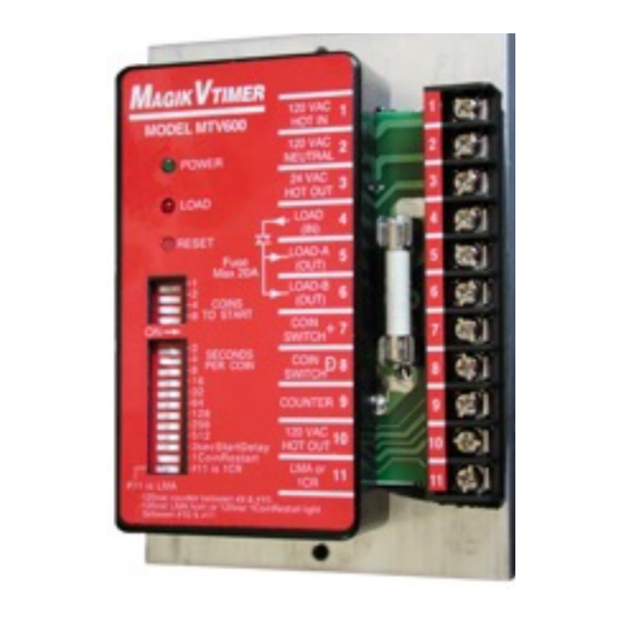
1.0 WIRING
The wiring diagram that follows shows the typical configuration for the
MTV600 timer in a vacuum cleaner. Power supply of 120 vac is supplied to
terminal 1 and 2. 24 vac power for the Magikist iCoin acceptors is provided on
terminals 3 and 8.
2.0 INDICATOR LIGHTS
The green POWER light on the timer shows that power is being supplied to the
timer. The red LOAD light indicates that the timer has been started and that the
output to the load is currently being timed.
3.0 SWITCH SETTINGS
To set a switch ON, depress the right side of the switch until it clicks into
position down. To turn a switch OFF, depress the left side until it clicks into
position down.
3.1 COIN SETTING
Set the switches labelled COINS TO START such that they total the number of
coins/pulses required to turn the load on. For example, to turn the load for 3
coins/pulses, set switches 1 and 2 on. To turn the load on for 6 coins/pulses,
set switches 2 and 4 on. If all the coin switches are off, the timer will be set for
1 coin/pulse and will operated as a non-accumulating timer. This is typically
used when a normally open momentary pushbutton is connected to terminals
7 and 8. An optional MTV600-85 wire connector is available for non-
accumulating configurations that allows connection of a normally open
momentary stop button.
3.2 TIME SETTING
Set the switches labelled SECONDS PER COIN such that they total the number
of seconds per coin/pulse that the timer is to operate for. For example, to
Advertisement

Related Manuals for Magikist MAGIKVTIMER MTV600

Summary of Contents for Magikist MAGIKVTIMER MTV600
- Page 1 The wiring diagram that follows shows the typical configuration for the MTV600 timer in a vacuum cleaner. Power supply of 120 vac is supplied to terminal 1 and 2. 24 vac power for the Magikist iCoin acceptors is provided on terminals 3 and 8.
- Page 2 WIRING DIAGRAM • for the VB0 vacuum 120 VAC B W G TIMER AGIK 120 VAC MODEL MTV600 HOT IN 120 VAC VACUUM POWER NEUTRAL MOTORS 24 VAC HOT OUT LOAD LOAD (IN) SWITCH SETTINGS RESET LOAD-A (OUT) LOAD-B COINS (OUT) TO START COIN...