
Related Manuals for JDV JBSM

Summary of Contents for JDV JBSM
- Page 1 JDV CONTROL VALVES CO.,LTD. Installation, Operation and Maintenance 3-PC Floating Type Threaded / Welded Metal Seat Ball Valve VERSON: V 1.0 ISSUING DATE: 2015/11/02 1 of 18...
-
Page 2: Table Of Contents
Product Transportation/Storage/Maintenance --------------------------6、7、8 Notes for Preparation of Installation ----------------------------------------9、10 Notes prior to Operation ----------------------------------------------10、11、12 Routine Maintenance and Troubleshooting ------------------------------13、14 JBSM -15、16 Structure Diagram / Procedure of Disassembling and Assemblag JBSM-EXTENDED Structure Diagram / Procedure of Disassembling and Assemblag--------------------------------------------------------------------17、18 2 of 18... -
Page 3: Overview
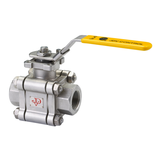
Overview: JBSM is a 3-PC Floating Type Threaded /Welded Metal Seat Ball Valve of JDV. Features of the product comprise: 1. Anti-static device: Static is generated by valve ball due to friction with fluid flow, and the static cannot be conducted to exterior of the body. -
Page 4: Notes Prior To Use
Notes prior to Use: 1. Read the instructions for installation, operation, maintenance carefully before operating the product. 2. Identify the warning banners and descriptions mentioned in this document. 3.Do not use in excess of the design pressure of the valve case. 4.Do not use in case of over temperature valve designs. -
Page 5: Warning Banners
Warning Banners: Banner Description This indicates a dangerous situation. Slight or moderate injury might be resulted if it is not averted. Death or severe injury might be resulted if such potential dangerous situation is not averted. Safety Notification: Design engineers or product users identify basic product specifications and check the compliance of valve and installation equipment in order to guarantee safe use. - Page 6 Warning: 1. In moving or transportation, suitable tools have to be selected for correct equipments and accessories (sling, fastener, hook and so forth) in terms of size with consideration of individual weights of details in the package and the complete total weight. 2.
- Page 7 Preserving of Packed Ball Valve 1. Protect the pack adequately to prevent the pack from damage. 2. There should be warning banners for packs to guarantee that the moving of product would not result in unnecessary damage, such as suspending center of gravity 3.
-
Page 8: Notes For Preparation Of Installation
Preserving of non-packed/unpacked ball valve 1. Please guarantee appropriate protection of the product in order to prevent it from damage. 2. In treating large valve, the product has to be fixed safely and stably. Suitable tools (bracket, hook, fastener, cable) should be used in transportation. -
Page 9: Notes Prior To Operation
6. In valve installation, please use wrench and follow diagonal sequence (Figure 1) to lock screws in order to prevent flange from deformation. 圖一 Notes prior to Operation Manual Valve: 1.In manual operation, over or inadequate operation would damage handle or components, or result in indirect leakage. - Page 10 ※ Closed position of ball valve – please identify that the notch direction on top of stem on the ball valve is vertical to the direction of the handle and channel, and the ball valve is in closed status. (Figure 3) Notch for Stem (Figure 3) Pneumatic Ball Valve:...
- Page 11 Maintenance and Troubleshooting Routine Mai ntenance * Maintain routine maintenance and check to guarantee good operability. For fastening torque, refer to the torque tables for each specification. ANSI 600LB / DIN PN100 JBSM JBSM-EXTENDED Joint Bolt Torque Torque Gland Bolt...
- Page 12 Troubleshooting Area Problem Description Solution 1. Please check whether the surface of BALL(3) and SEAT(4) have scratches or any damage. 2. Replace the SEAT GASKET(5) when the surface of ball and valve seat have not Internal Leak at the surface scratches or any damage.
- Page 13 Structure/disassembly/assembly 1/2"~2" JBSM Structure BODY BALL SEAT SEATGASKET SEAT RETAINER SEAT SPRING BODY GASKET STOPPER BOLT & NUT THRUST WASHER GLAND PACKING STEM RING BEVEL WASHER PACKING LOCK WASHER HANDLE HANDLE NUT 13 of 18...
- Page 14 ● Disassembly 1. Turn BALL (3) to full “closed” position. 2. Remove HANDLE NUT (19), HANDLE(18) and STOPPER(9). 3. Remove PACKING LOCK WASHER (17), loose NUT (16), then take BEVEL WASHER (15) out. 4. Loose BOLT & NUT (10), remove CAP (2) and BODY GASKET (8). 5.
- Page 15 ● Assembly 1. Put THRUST WASHER(11) on STEM(13), than install STEM(13) into BODY(1). 註: 2. Insert BALL into BODY (1). PS. Be careful to assemble, in order to avoid collision and damage the sealing surface. 3. Put SEAT GASKET (5), SEAT RETAINER (6), SPRING (7), SEAT (4) on CAP (2) orderly.
- Page 16 1/2"~2" JBSM-EXTENDED structure BODY BALL SEAT SEATGASKET SEAT RETAINER SEAT SPRING BODY GASKET BOLT & NUT THRUST WASHER GLAND PACKING STEM GLAND GLAND BOLT GLAND BEARING BONNET BONNET GASKET BONNET BOLT 16 of 18...
- Page 17 ● Disassembly 1. Turn BALL (3) to close position. 2. Loose GLAND BOLT (14), remove GLAND (13) and GLAND BEARING (15) 3. Loose BOLT & NUT (9) and take out CAP (2) and BODY GASKET (8). 4. After remove CAP (2), take out SEAT (4), SEAT SPRING (7), SEAT RETAINER (6) and SEAT GASKET (5) 5.
- Page 18 ● Assembly 1. Put THRUST WASHER (10) on STEM (12), install STEM (12) into BODY (1). 2. Install GLAND PACKING (11), BONNET GASKET (17), BONNET (16) to BODY (1) orderly, and Screw BONNET BOLT (18) to tighten. 3. Put BALL (3) into BODY (1). PS.
Need help?
Do you have a question about the JBSM and is the answer not in the manual?
Questions and answers