Table of Contents
Advertisement
Quick Links
Advertisement
Table of Contents

Related Manuals for ATV Falcon FA-HDX16-2TB

Summary of Contents for ATV Falcon FA-HDX16-2TB
- Page 3 Digital Video Recorder WARNING RISK OF ELECTRIC SHOCK DO NOT OPEN WARNING: TO REDUCE THE RISK OF ELECTRIC SHOCK, DO NOT REMOVE COVER (OR BACK). NO USER-SERVICEABLE PARTS INSIDE. REFER SERVICING TO QUALIFIED SERVICE PERSONNEL. The lightning flash with arrowhead symbol, within an equilateral triangle, is intended to alert the user to the presence of uninsulated "dangerous voltage"...
- Page 4 User’s Manual Important Safeguards 1. Read Instructions 14. Damage requiring Service All the safety and operating instructions should be read before the Unplug this equipment from the wall outlet and refer servicing to qualified service personnel under the following conditions: appliance is operated.
-
Page 5: Table Of Contents
Digital Video Recorder Table of Contents Chapter 1 — Introduction ......................1 Feature ........................... 1 Technical Overview ........................ 1 Chapter 2 — Installation ......................3 Package Contents ........................3 Required Installation Tools ....................3 Video Input......................... 3 Video Loop Through ......................4 Factory Reset Switch ...................... - Page 6 User’s Manual Account ..........................18 Storage ..........................19 Monitoring ........................21 Recording Setup ........................22 General ..........................22 Schedule .......................... 23 Pre-Event ......................... 25 Archive ..........................26 Network Setup ........................26 General ..........................26 IP Address ........................28 DVRNS ..........................29 RTSP ..........................
- Page 7 Digital Video Recorder Searching Video ........................56 Search Menu ........................56 Event Log Search ......................58 Record Table Search ....................... 59 Motion Search ......................... 61 Text-In Search ......................... 62 Bookmarks ........................63 Clip-Copy ......................... 64 Print ..........................66 Disk Mirroring ........................66 Appendix ..........................
- Page 8 User’s Manual Figure 16 : Record – Pre-Event setup screen..................25 Figure 17 : Record – Archive setup screen..................... 26 Figure 18 : Network – General setup screen................... 27 Figure 19 : Network – IP Address (Manual) setup screen............... 28 Figure 20 : Network –...
-
Page 9: Chapter 1 - Introduction
Digital Video Recorder Chapter 1 — Introduction Feature Your color digital video recorder (DVR) provides recording capabilities for 16 camera inputs. It provides exceptional picture quality in both live and playback modes, and offers the following features: 16 Composite Video Input Connectors ... -
Page 10: Figure 1 : Typical Dvr Installation
User’s Manual Your DVR uses a proprietary encryption scheme making it nearly impossible to alter video. You can view video and control your DVR remotely by connecting via Ethernet. There are eSATA and iSCSI ports that can be used to record or archive (eSATA interface only) video to external hard disk drives, and there are two USB ports that can be used to upgrade the system or copy video clips to external hard disk and flash drives. -
Page 11: Chapter 2 - Installation
Digital Video Recorder Chapter 2 — Installation Package Contents The package contains the following: Digital Video Recorder Power Cord User’s Manual (This Document) ATVision Software CD and User’s Manual Rack-mount Kit Assembly Screws for Adding Hard Disk Drives ... -
Page 12: Video Loop Through
User’s Manual Video Loop Through If you would like to connect your video source to another device, you can use the Loop BNC connectors. NOTE: The Loop BNC connectors are auto terminated. Do NOT connect a cable to the Loop BNC unless it is connected to a terminated device because it will cause poor quality video. -
Page 13: Esata Port
Digital Video Recorder CAUTION: If the iSCSI device is shut down while the device is operating, the DVR system might not operate normally. eSATA Port An eSATA port is provided to connect external storage devices for recording or archiving video. Connect the external eSATA hard disk drive (RAID) cable to the eSATA port. -
Page 14: Audio In/Out
User’s Manual Audio In/Out Your DVR can record audio from up to 16 sources. Connect the audio sources to Audio In 1 to Audio In 16 as needed using RCA jacks. Connect Audio Out to your amplifier. Use the provided audio extension cable to connect the audio sources to Audio In 5 to 16. -
Page 15: Power Cord Connector
Digital Video Recorder Power Cord Connector Connect the AC power cord to the DVR and then to a wall outlet. WARNING: ROUTE POWER CORDS SO THAT THEY ARE NOT A TRIPPING HAZARD. MAKE CERTAIN THE POWER CORD WILL NOT BE PINCHED OR ABRADED BY FURNITURE. DO NOT INSTALL POWER CORDS UNDER RUGS OR CARPET. - Page 16 User’s Manual...
-
Page 17: Chapter 3 - Configuration
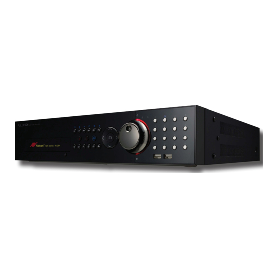
Digital Video Recorder Chapter 3 — Configuration NOTE: Your DVR should be completely installed before proceeding. Refer to Chapter 2 — Installation. Front Panel Controls Figure 3 : DVR front panel. Camera Buttons Jog Dial, Shuttle Ring Enter Button Arrow Buttons Playback Buttons PTZ Button Alarm Button... -
Page 18: Camera Buttons (1 To 16)
User’s Manual Figure 4 : Infrared remote control. NOTE: For simplicity, the button descriptions in this manual refer to the front panel buttons. Camera Buttons (1 to 16) Pressing the individual camera buttons will cause the selected camera to display full screen. Buttons 1 to 9 are also used to enter passwords. -
Page 19: Arrow Buttons
Digital Video Recorder Arrow Buttons These buttons are used to navigate through menus and GUI. You can also use them to change numbers by highlighting a number in the menu and using the Up and Down arrow buttons to increase or decrease the number’s value. These buttons are also used to control Pan and Tilt when in the PTZ mode. -
Page 20: Zoom Button
User’s Manual ZOOM Button Pressing the button zooms the current image on the screen. A PIP with a rectangle temporarily displays showing ZOOM what area of the screen has been enlarged. You can use the arrow buttons to move the rectangle to another area. NOTE: Entering the zoom mode is NOT supported while in the SD display mode. -
Page 21: Turning On The Power
Digital Video Recorder Turning on the Power Connecting the power cord to the DVR turns on the unit. The unit takes approximately 60 seconds to initialize. Initial Unit Setup Before using your DVR for the first time, you will want to establish the initial settings. This includes items such as time and date, display language, camera, remote control, record mode, network and password. -
Page 22: Setup Screen
User’s Manual Setup Screen System Record Network Event Device Display Status Camera Figure 7 : Setup screen. Press the button or move the mouse pointer to the top of the screen and then select (Setup) in the Live MENU Monitoring menu to enter the setup screen. While setting up the DVR, there will be many opportunities to enter names and titles. -
Page 23: Figure 8 : System - General Setup Screen
Digital Video Recorder Figure 8 : System – General setup screen. In the General screen, you can name the site location, assign a System ID number, select the language the screens are displayed in, display software version number, upgrade the software, show the System Log, display recorded time data, and clear all data. - Page 24 User’s Manual You can import saved DVR settings or export the current DVR settings. To import saved DVR settings, connect the USB device containing the setup file (.dat) to the DVR. Highlight Setup – Import… and press the button. Select the desired setup file and press the Import button to import the selected settings and change the DVR settings accordingly.
-
Page 25: Date/Time
Digital Video Recorder After selecting Shutdown and pressing the button, a screen will appear telling you when it is safe to disconnect power. Date/Time Highlight Date/Time and press the button, and the Date/Time setup screen appears. Figure 9 : System – Date/Time setup screen. Highlight the first box beside Date and press the button. -
Page 26: Account
User’s Manual Highlight the box beside Interval and press the button. Set the time interval for synchronization from 30 minutes to 1 day at various time intervals. Last Sync-Time displays the last time the DVR was synchronized with the time server. Highlight Run as Server and press the button. -
Page 27: Storage
Digital Video Recorder column can be used to delete a User Name or an entire Group. If the is grayed out, that Group or User cannot be deleted. Highlight the and press the button. You will be asked to confirm that you want to delete the User or Group. -
Page 28: Figure 11 : System - Storage Setup Screen
User’s Manual Figure 11 : System – Storage setup screen. The information in the Type column describes the storage device. The capacity of the storage device is displayed in the Capacity column. The Format column displays whether the device is used for recording (Record), archiving (Archive) or not (Not Using). Not formatted indicates the device is not formatted. -
Page 29: Monitoring
Digital Video Recorder Monitoring Highlight Monitoring and press the button, and the Monitoring setup screen appears. Figure 12 : System – Monitoring setup screen. The DVR can be configured to run self-diagnostics and report the results. Highlight the Settings box beside the desired event (System, Check Recording, Check Alarm-In, Disk Almost Full, Disk Bad, or Disk Temperature), and press the button. -
Page 30: Recording Setup
User’s Manual NOTE: Alarm-Out action cannot be set to System and Panic Record events. Mail notify is the only option available for the System event. For the Notify action to work, the DVR should be registered in the ATVision (Remote Administration System). Recording Setup General Highlight General and press the... -
Page 31: Schedule
Digital Video Recorder NOTE: When the storage device does not have enough space to record video data longer than the preset Limit Time-Lapse Recording period, the DVR records over the oldest video data (time-lapse or event video) as it would in the Recycle mode even if this feature is turned On. The maximum storage time is only an estimate because the amount of space required to store video varies depending on many factors such as motion and image complexity. -
Page 32: Figure 15 : Schedule - Settings (Advanced Mode) Setup Screen
User’s Manual Highlight the Schedule Mode box and press the button. You can select between Simple Mode and Advanced Mode. Selecting Advanced Mode allows you to set up individual recording schedule for each event. NOTE: Changing the schedule mode will reset all event and action statuses. Highlight the + and press the button to add a schedule item. -
Page 33: Pre-Event
Digital Video Recorder NOTE: When multiple events are detected at the same time from a specific channel, the DVR will record event video with the high setting values if the ips, Quality, Resolution and Dwell values of events are different from each other. -
Page 34: Archive
User’s Manual NOTE: When the DVR is in the Time or Time & Event mode, it ignores the pre-event settings and follows the time settings. Archive Highlight Archive and press the button, and the Archive setup screen appears. Figure 17 : Record – Archive setup screen. Highlight Archive On and press the button to toggle between On and Off. -
Page 35: Figure 18 : Network - General Setup Screen
Digital Video Recorder Figure 18 : Network – General setup screen. You can limit the network bandwidth settings so that system does not consume too much network bandwidth. Highlight the box beside Network Bandwidth Limit and press the Up and Down arrow buttons to set the desired maximum bandwidth from 50Kbps to 1Gbps. -
Page 36: Ip Address
User’s Manual IP Address Highlight IP Address and press the button, and the IP Address setup screen displays. Figure 19 : Network – IP Address (Manual) setup screen. Highlight the box beside Type and press the button. You can select the type of network configuration from: Manual, DHCP and ADSL (with PPPoE). -
Page 37: Dvrns
Digital Video Recorder NOTE: For the UPnP service to work, the NAT device should support the UPnP Port Forwarding function and the function should be set to enabled. You cannot change the port settings when Use UPnP is On. Highlight the Status box and press the button to display the port numbers forwarded from the NAT device via UPnP service. -
Page 38: Rtsp
User’s Manual NOTE: The DVRNS (DVR Name Service) allows the DVR to use Dynamic IP addresses for remote connection. When this feature is On, you can access your DVR remotely using the DVR name instead of its IP address. For the DVRNS feature, the DVR should be registered on the DVRNS server. Highlight the box beside DVRNS Server and press the button. -
Page 39: Notification
Digital Video Recorder Highlight the box beside RTP End Port and press the button. Set the end port number of the RTP server obtained from your system administrator. Highlight Use Mobile and press the button to toggle between On and Off. When set to on, you can access a remote DVR using a Blackberry or other mobile devices. -
Page 40: Iscsi
User’s Manual Highlight the box beside Port and press the button. Use the arrow buttons to enter the SMTP Server port number obtained from your system administrator. The default port number is 25. Highlight Use SSL/TLS and press the button to toggle between On and Off. When it is On, the DVR can send an email via an SMTP server requiring SSL (Secure Sockets Layer) authentication. -
Page 41: Event Setup
Digital Video Recorder Highlight the iSCSI – Target Address box and press the button. Use the arrow buttons to enter the IP address of the iSCSI device that you are connecting to the DVR. Highlight the iSCSI – Target Port box and press the button. -
Page 42: Figure 24 : Event - Motion Setup Screen
User’s Manual Figure 24 : Event – Motion setup screen. Your DVR has built-in video motion detection. Video motion detection can be turned On or Off for each camera. Highlighting the box under the Sensitivity heading and pressing the button allows you to adjust the DVR’s sensitivity to motion for Daytime and Nighttime independently. -
Page 43: Alarm-In
Digital Video Recorder Highlighting the box under the Actions and pressing the button. The DVR can be set to react to motion detection differently for each camera. Each camera can be associated with another camera, trigger an Alarm-Out connector, sound the DVR’s internal buzzer, notify a number of different devices, move PTZ cameras to preset positions, and/or display a camera on a SPOT monitor. -
Page 44: Video Blind
User’s Manual Figure 26 : Event – Video Loss setup screen. Highlighting the box under the Actions and pressing the button. The DVR can be set to react to video loss differently for each camera. Each camera can be associated with another camera, trigger an Alarm-Out connector, sound the DVR’s internal buzzer, notify a number of different devices, move PTZ cameras to preset positions, and/or display a camera on a SPOT monitor. -
Page 45: Text-In
Digital Video Recorder NOTE: Video blind might NOT be detected for a camera with a very noisy image especially when set for low sensitivity values. Highlighting the box under the Activation Time heading allows you to set the duration before the DVR will report a Video Blind. -
Page 46: Device Setup
User’s Manual Highlight the box beside Port, and press the button. Select from None, RS232, RS485, USB-Serial (1~8) and LAN (1~16). NOTE: If you have set the Port as None, you will not be able to make any changes to the screen. When using the USB to serial text-in device, do NOT remove the USB cable from the port while the system is running. -
Page 47: Alarm-Out
Digital Video Recorder Figure 30 : Device – Audio setup screen. The DVR can record up to 16 audio inputs. Highlight the box beside the input and press the button. A list of cameras appears, and you can select which camera you want associated with that audio input. Highlight Enable Audio-Out and press the button. -
Page 48: Remote Control
User’s Manual Highlighting the boxes under the Range box and pressing the button allows you to set the time that the alarm schedule will be active in 15-minute increments from 00:00 to 24:00. Highlighting the boxes under the Mode box and pressing the button allows you to set how the alarm reacts during the scheduled time. -
Page 49: Primary Monitor
Digital Video Recorder Figure 33 : Display – OSD setup screen. Highlighting an item and pressing the button toggles that item On and Off. When an item is On, there is a checkmark in the box beside it. The following items can be turned On or Off: ... -
Page 50: Figure 34 : Display - Primary Monitor Setup Screen
User’s Manual Figure 34 : Display – Primary Monitor setup screen. Highlight the box beside Mode and press the button. You can select between Full Sequence and Cameo Sequence. Pressing the SEQUENCE button on the remote control or selecting (Sequence) in the Live Monitoring menu causes the DVR to sequence cameras, and the DVR can sequence cameras in two modes: “Full”... -
Page 51: Secondary Monitor
Digital Video Recorder NOTE: The system restarts automatically after changing the resolution settings. If the system restarts when the monitor is not connected, the resolution will be set to 1280x1024@60Hz as default without saving your changes. When the individual primary monitors are connected to the HDMI and VGA connectors for simultaneous operation, it is recommended to use monitors supported with the same resolution. -
Page 52: Status Setup
User’s Manual Figure 36 : Display – Spot Monitor setup screen. Highlight the box in the Channels column and press the button. You can define which cameras display sequentially on the Spot Monitor when in the single-screen display format. Highlighting the box under the Camera and pressing the button toggles between On and Off. -
Page 53: Storage
Digital Video Recorder Figure 37 : Status – Event setup screen. The Event Status screen displays the status of the DVR’s systems and inputs. Events will be highlighted, and related channels or events will flicker for five seconds when detected. Alarm-In, Motion, Video Loss, Video Blind and Text-In will be highlighted when each event is detected based on the settings you made in the Alarm-In, Motion, Video Loss, Video Blind and Text-In setup screen on the Event menu. -
Page 54: Camera Setup
User’s Manual The Type column displays the type of storage device. The Disk Bad column displays the percentage of bad sectors. Not formatted indicates the device is not formatted. The Temperature column displays the temperature of the storage device. The S.M.A.R.T. column displays “Good”, “Bad” or “N/A”, depending on storage conditions. ... -
Page 55: Figure 40 : Camera - Ptz Setup Screen
Digital Video Recorder Figure 40 : Camera – PTZ setup screen. NOTE: You will only be able to set up PTZ devices if the PTZ port is set to RS232 or RS485. Highlight the box in the Product column for the PTZ camera you wish to configure and press the button. - Page 56 User’s Manual...
-
Page 57: Chapter 4 - Operation
Digital Video Recorder Chapter 4 — Operation NOTE: This chapter assumes your DVR has been installed and configured. If it has not, please refer to Chapters 2 and 3. The DVR’s controls are similar to a VCR. As with a VCR, the main functions are recording and playing back video. However, you have much greater control over recording and playing back video. -
Page 58: Live Monitoring Menu
User’s Manual Live Monitoring Menu Login/Logout Selecting (Login) in the Live Monitoring menu accesses the Login screen, and you will be asked to select a User and enter the password to log into the system. Selecting (Logout) in the Live Monitoring menu displays the Logout screen asking you to confirm whether or not you want to log out the current user. -
Page 59: Active Cameo Mode
Digital Video Recorder Selecting again in the Live Monitoring menu exits the Sequence mode. While in the Sequence mode, the icon displays in bottom-left corner if Sequence is selected in the Display setup screen (OSD tab). If all the cameras in a page are Off, or have lost video or are set to Covert (unless the user has authority to view covert cameras), that page will be excluded from the sequence. -
Page 60: Zoom Mode
User’s Manual Zoom Mode You can enlarge an area of the video by pressing the button. For a few seconds after pressing the button, ZOOM ZOOM a rectangle displays on the screen. A rectangle shows the area that will be enlarged. You can move the rectangle around using the arrow buttons. -
Page 61: Event Monitoring
Digital Video Recorder While in the PTZ mode, pressing the button and selecting (Advanced PTZ) in the menu MENU displaying at the top of the screen displays the Advanced PTZ menu. Set the feature you wish to control by selecting it from the menu. Refer to the camera manufacturer’s instructions for the proper settings. -
Page 62: Recording Video
User’s Manual (Display) → Screen Format in the Live Monitoring menu and then select the screen mode between 2x2 Select and 4x4 you want to display on a Spot Monitor. Selecting (Sequence) in the Live Monitoring menu causes the cameras to display sequentially, and selecting again stops sequencing on a Spot Monitor. -
Page 63: Figure 44 : Select Playback Camera Menu
Digital Video Recorder Selecting All Channels plays back video of all cameras. The DVR maintains the same display format as it does in the live mode. You can also change the screen layout in the same way as you do in the live mode. -
Page 64: Searching Video
User’s Manual Go to the previous image Play/Pause Go to the next image Fast backward play Fast forward play Searching Video While in the search mode, pressing the button displays the following Search menu at the top of the screen. MENU Pressing the button again hides the menu. - Page 65 Digital Video Recorder Bookmark: Selecting (Go To) → Bookmark adds the current playback point to the bookmark list. See the following Bookmarks section for details. Display Camera: Selecting (Display) → Camera and choosing the camera number displays the selected camera full screen.
-
Page 66: Event Log Search
User’s Manual Data Source Selecting (Data Source) in the Search menu allows you to select the data source to be searched. Selecting Record searches recorded data on primary storage installed in the DVR, and selecting Archive searches archived data on secondary storage installed in the DVR. -
Page 67: Record Table Search
Digital Video Recorder You can search video from the first to last recorded images, or you can set the start and stop times and dates. Highlight the box beside From and press the button to toggle between On and Off. When set to Off, you can enter a specific Date and Time. -
Page 68: Figure 47 : Record Table Search Screen
User’s Manual < Expanded View > Figure 47 : Record Table Search screen. Recording information about video images currently displayed on the screen displays on the recording status bar. A grey vertical line indicates the current search position. To search specific video, move the vertical line by using the Left or Right arrow buttons on the front panel or by clicking the mouse on the desired segment. -
Page 69: Motion Search
Digital Video Recorder Selecting located at the bottom displays the Search menu. Go To: Displays the first or last recorded image, searches by date and time, or adds the current playback point to the bookmark list (see the previous Searching Video – Go To and Bookmarks sections of this chapter for more details). -
Page 70: Text-In Search
User’s Manual Highlight the box beside From and press the button to toggle between On and Off. When set to Off, you can enter a specific Date and Time. When set to On, the search will be from the first recorded image. Highlight the box beside To and press the button to toggle between On and Off. -
Page 71: Bookmarks
Digital Video Recorder NOTE: It is possible that no recorded image displays on the current screen. Press the button and change DISPLAY the screen mode to 4x4. You will be able to easily see the camera have recorded video during target time. Text Input information will be overlaid on the image while the recorded video is played at regular speed. -
Page 72: Clip-Copy
User’s Manual Highlight the Add Current Position box and press the button to add the current playback point to the bookmark list. Highlight the Title box and enter the name of the registered bookmark. Use the virtual keyboard to enter the bookmark name. NOTE: Up to eight bookmarks can be registered. - Page 73 Digital Video Recorder Highlight the box beside Channels and press the button. You can select the cameras that you would like to include in your video clip. Highlight the box beside Channels and press the button. You can select the cameras that you would like to include in your video clip.
-
Page 74: Print
User’s Manual CAUTION: Do NOT disconnect the USB cable or the power from the external drive while copying video clips. If the external drive is shut down or the USB cable is disconnected while copying video clips, THE DVR SYSTEM MAY NOT WORK NORMALLY OR THE EXTERNAL DRIVE COULD BE DAMAGED, and you will get an error message the next time you try to copy video clips. - Page 75 Digital Video Recorder You can enable mirroring between two disks by designating the source disk and the destination disk from a list of internal hard disk drives. Up to two Mirrors are supported. Highlighting the boxes under Source and Dest. and pressing the button allows you to select the source disk and the destination disk for the selected Mirror.
- Page 76 User’s Manual...
-
Page 77: Appendix
Digital Video Recorder Appendix USB Hard Disk Drive Preparation Preparing the USB hard disk drive in Windows 2000 NOTE: Preparing a USB hard disk drive under Windows XP, Window Vista and Window 7 is almost identical to Windows 2000. Connect the USB hard disk drive to your computer using the USB Cable. Turn on your computer. -
Page 78: Text-In Search Examples
User’s Manual Text-In Search Examples Search Example I 123456789012345678901234567890123456789012345678901234567890 Item Unit price amount ================================================== Coke 2.20 | 1(s) | $ 2.20 Fanta 2.20 | 1(s) | $ 2.20 Hotdog 3.50 | 3(s) | $ 10.50 Pepsi 1.95 | 1(s) | $ 1.95 ================================================== total : $... -
Page 79: Atvision
Digital Video Recorder In the above text-in data, you can find that the comparison value is located at 17th (Unit price, $ mark will be ignored automatically), 28 (Qty) and 40 (amount) characters (including spaces) from the left, but the value of amount category is located on a different line from Item. -
Page 80: Web Monitoring Mode
User’s Manual You will need to enter the DVR IP address in the DVR ADDRESS field when running the ATVision program by entering http://www.dvronline.net. Selecting the Use DVRNS option allows you to enter the DVR name registered on the DVRNS server instead of the IP address. You must enter the DVRNS server address and port number in the SETUP setting when selecting the Use DVRNS option. -
Page 81: Web Search Mode
Digital Video Recorder ① Click the to log out the ATVision program. ② Click the to access to the web search mode. ③ Position the mouse pointer on the ATVISION logo to see the version of the ATVision program. ④ The DVR information window displays the login information of ATVision. ⑤... - Page 82 User’s Manual ① Click the to log out the ATVision program. ② Click the to access to the web monitoring mode. ③ Position the mouse pointer on the ATVISION logo to see the version of the ATVision program. ④ The DVR information window displays the time information of recorded data on the remote DVR and login information of ATVision.
-
Page 83: Time Overlap
Digital Video Recorder ⑭ Selecting a camera on the screen and clicking the right mouse button displays the text menu screen. Change Camera Title: Changes the camera name. Enable Audio: Plays audio while playing back recorded video that has recorded audio. (Single-Screen Layout Only) ... -
Page 84: Map Of Screens
User’s Manual Map of Screens... -
Page 85: Troubleshooting
Digital Video Recorder Troubleshooting Problem Possible Solution Check power cord connections. No Power Confirm that there is power at the outlet. Check camera video cable and connections. Check monitor video cable and connections. No Live Video ... -
Page 86: Error Code Notices
User’s Manual Error Code Notices System Upgrade Related Clip Copy Related Description Description Unknown error. Unknown error. File version error. Device error. Operating system version error. Mounting failed. Software version error. No media. Kernel version error. Invalid media. Upgrade device mounting failed. File already existed. -
Page 87: I/O Connector Pin Outs
Digital Video Recorder I/O Connector Pin Outs AI (1 to 16) Alarm Inputs 1 to 16 Chassis Ground (5 connectors) Relay Alarm Output (Normally Closed) Relay Common Relay Alarm Output (Normally Open) Alarm Reset In Specifications VIDEO Signal Format NTSC or PAL (Auto Detect) Video Input Composite: 16 looping inputs, 1 Vp-p, auto-terminating, 75 Ohms Primary Monitor... - Page 88 User’s Manual CONNECTORS Video Input Composite: 16 BNC Video Loop Composite: 16 BNC (Auto Terminating) HDMI: 1 HDMI Composite: 1 BNC Monitor Output VGA: 1 VGA SPOT (Composite): 1 BNC Audio In 16 RCA connector Audio Out 1 RCA connector Alarm Input/Output Terminal Blocks Ethernet Port...
Need help?
Do you have a question about the FA-HDX16-2TB and is the answer not in the manual?
Questions and answers