Table of Contents

Related Manuals for Sonifex AVN-TB20AR


Summary of Contents for Sonifex AVN-TB20AR
- Page 1 AVN-TB20AR 20 Button Advanced Rackmount Talkback Intercom, AoIP Portal AVN-TB20AD 20 Button Advanced Desktop Talkback Intercom, AoIP Portal Manufacturers of Audio Products for AV, Installed Sound, Broadcast Radio & Broadcast TV...
-
Page 2: Table Of Contents
Informa�on in this document is subject to change without no�ce and does not represent a Reset Switch commitment on the part of the vendor. Sonifex Ltd shall not be liable for any loss or damage whatsoever arising from the use of informa�on or any error contained in this manual. - Page 3 AVN-TB20AR & AVN-TB20AD Handbook Contents & Figures Contents continued… Channel 1 to 20 Intercom Call Buttons Ending a Call Listen Button Group Calls Page Button Call Signal GPI/O Button Auto Answer Phone Button Listen Button Mic Mute Button Reviewing Channel Assignments...
- Page 4 The AVN-TB20AD Front Panel AoIP Setup Fig 2-1: Preferred Network Topology PTP Setup Fig 3-1: AVN-TB20AR and AVN-TB20AD Front Panels 5 Display Fig 3-2: Main Screen in the Idle State Mic Setup Fig 4-1: AVN-TB20AR and AVN-TB20AD Rear Panels 10...
- Page 5 Contents & Figures Figures continued… Fig 13-13: Front Panel - Display Settings Web Page Fig 13-14: Front Panel - Colour Settings Web Page Fig 13-15: Front Panel - User Button Settings Web Page Fig 13-16: Audio - Microphone Settings Web Page Fig 13-17: Audio - Input Settings Web Page Fig 13-18:...
-
Page 6: Tel: +44 (0)1933 650
To register your product, please go online to www.sonifex.co.uk/register Sonifex Limited ● 61 Station Road ● Irthlingborough ● Northamptonshire ● NN9 5QE ● United Kingdom Tel: +44 (0)1933 650 700 ● Fax: +44 (0)1933 650 726 ● Email: technical.support@sonifex.co.uk ● Internet: www.sonifex.co.uk... -
Page 7: Sonifex Warranty & Liability Terms & Conditions
Company and the Purchaser. Sonifex Limited ● 61 Station Road ● Irthlingborough ● Northamptonshire ● NN9 5QE ● United Kingdom Tel: +44 (0)1933 650 700 ● Fax: +44 (0)1933 650 726 ● Email: technical.support@sonifex.co.uk ● Internet: www.sonifex.co.uk... -
Page 8: Unpacking Your Product
Warranty CE Conformity vii. the Goods have been assembled or incorporated into other results of that test. The report will be accurate at the �me of the test, goods only in accordance with any instruc�ons issued by the to the best of the belief and knowledge of the Company, and the Company;... -
Page 9: Repairs & Returns
The available voltage se�ngs are 115V, or 230V. Please note that all products are either switchable between 115V and 230V, Please contact Sonifex or your supplier if you have any problems with your or have a universal power supply. -
Page 10: Weee Directive
All products manufactured by Sonifex Ltd have the WEEE direc�ve label Connect the equipment in accordance with the connec�on details and placed on the case. Sonifex Ltd will be happy to give you informa�on about before applying power to the unit, check that the machine has the correct local organisa�ons that can reprocess the product when it reaches its “end... -
Page 11: Avn-Tb20Ar & Avn-Tb20Ad 20 Button Advanced Talkback Intercom, Aoip Portal Introduction
The AVN-TB20AR and AVN-TB20AD are 20 channel talkback intercom control units from the Sonifex range of IP based AVN (Audio/Video/Network) products. The AVN-TB20AR is a 2U rack mount version and the AVN-TB20AD is a desktop version that can be fi�ed flush into a work surface if required. - Page 12 The AVN range use RAVENNA as the communica�on method providing compa�bility with other AES67 systems. The AVN-TB20AR and AVN-TB20AD are advanced feature set units. Each of the 20 channels can be configured to provide communica�ons with other remote networked intercom units or AoIP streams, or with local 4-wire systems.
-
Page 13: Installation
Introduction Installation 2. Installation Network Connection The AVN-TB20AR and AVN-TB20AD have 2 separate gigabit network ports: Upper Port: Configura�on and control interface Lower Port: Audio over IP (AoIP) interface In an ideal installa�on, the lower port should be connected to a dedicated network switch that handles audio and audio related traffic only. -
Page 14: Microphone
12V DC power supply, part number AVN-DC150. microphone or headset should be connected. If phantom power is required, Please contact Sonifex Ltd sales for more details. Both power supplies can this can be enabled via the webserver. See Audio - Microphone Se�ngs... -
Page 15: Front Panel Controls, Connections & Indicators
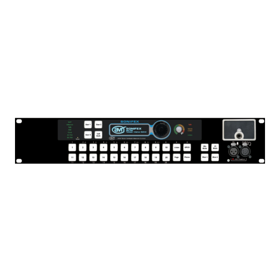
User 1 and 2 Rotary Encoder Bu�ons Control User 3 and Call Naviga�on Back Bu�ons Control Reset GPI/O Switch & Phone Bu�on Fig 3-1: AVN-TB20AR and AVN-TB20AD Front Panels Channel 1 to 20 Intercom Call Bu�ons Listen & Page Bu�ons... -
Page 16: Status Indicators
Front Panel Controls, Connections & Indicators Green The AGC is enabled. Status Indicators The RGB status indicators are located on the le� side of the front panel. The audio source level for one of the outputs is too high and is being limited. The monitored outputs are outputs AoIP 1-3 on the rear panel, the headphone/headset output and Indicates the status of AoIP services on the network as follows:... -
Page 17: Reset Switch
Front Panel Controls, Connections & Indicators DC PSU OLED Display Indicates the status of the DC power input as follows: The OLED display shows the current call and page status of the unit. Green DC voltage is within normal opera�ng range of +11V to +13V. -
Page 18: Headphone Output Connector
The phone bu�on allows the unit to control a compa�ble telephone hybrid When headphones are connected, the speaker mute is automa�cally device, such as the Sonifex DHY-04*. Calls can be made using either the ac�vated. telephone hybrid’s speed dial func�onality or by entering a number directly. -
Page 19: Ls Mute Button
Front Panel Controls, Connections & Indicators LS Mute Button Headset Connector This bu�on mutes the audio feed to the speaker. The bu�on illuminates red This 5 pin XLR socket is the connec�on for the headset. There is a parallel when the mute func�on is ac�ve. The opera�onal mode of the bu�on is headset connector on the rear panel. -
Page 20: Rear Panel Connections
Balanced Line S/PDIF Ethernet Stereo Line Input/Output Digital Network Output 2 Input Interface Stereo Stereo Stereo GPI/O AoIP AoIP Mains Mains AC Output 1 Input 1 Input 2 Network Fuse Input Interface Interface Input Fig 4-1: AVN-TB20AR and AVN-TB20AD Rear Panels... -
Page 21: Headset Connector
Rear Panel Connections The audio source for this output is configurable, see the Audio - Output Headset Connector Se�ngs web page on page 43 for more details. This 5 pin XLR socket is the connec�on for the headset. There is a parallel headset connector on the front panel. -
Page 22: S/Pdif Digital Input
Rear Panel Connections Quick Start Guide S/PDIF Digital Input Ethernet 1GB & AoIP 1GB Network Interfaces This RCA female connector is a stereo digital input which conforms to the S/PDIF (Sony/Philips Digital Interface) standard. The connec�ons are as follows: These RJ45 connectors are the gigabit network ports. The upper connector is the configura�on and control port and the lower connector is the audio Inner: Signal... -
Page 23: Quick Start Guide
53 for details. This sec�on outlines the steps required to get the AVN-TB20AR/AVN-TB20AD 7. If a dedicated grandmaster clock, such as the AVN-GMC from Sonifex, is connected to a network and in a state where it can make and receive going to be used as the master PTP clock for the network audio system, intercom calls. -
Page 24: Intercom Calls
They can also be the target unit. configured to interface to legacy 4-wire talkback units, such as the Sonifex CM-TB8. See the Channels - Advanced Se�ngs... -
Page 25: During A Call
Intercom Calls include any combina�on of channels, see the Group Talk web page on page During a Call 39 for details. Group calls are selected by assigning a group talk set to one When an intercom call is connected, the channel bu�on is illuminated using of the user bu�ons, see the Front Panel - User Bu�ons web page on page... -
Page 26: Reviewing Channel Assignments
Intercom Calls Intercom Calls with IFB If a channel bu�on is not pressed within 3 seconds of the last listen bu�on Call Functions press, the listen func�on is cancelled. The following table shows the corresponding call func�ons between the calling and receiving unit. The default channel bu�on colours for the call Reviewing Channel Assignments type is also shown. -
Page 27: Intercom Calls With Ifb
Intercom Calls 7. Intercom Calls with IFB Several models in the AVN Talkback range, including the AVN-TB20AR and AVN-TB20AD, can generate specific IFB AoIP streams. The content of the IFB feed is fully configurable as is the talk mode which determines how the audio in the IFB feed is modified when a call is ac�ve. -
Page 28: Non-Intercom Calls
Intercom Mode 8. Non-Intercom Calls The AVN-TB20AR and AVN-TB20AD allow any AoIP stream to be assigned to the channel bu�ons. When a call is ini�ated to a non AVN Talkback device, the unit does not a�empt to communicate with the remote device for call control. -
Page 29: Intercom Mode
Intercom Mode 9. Intercom Mode The AVN-TB20AR and AVN-TB20AD have an intercom mode se�ng that controls the rou�ng of audio to and from remote AoIP devices. The se�ng has 2 op�ons, Normal Mode and 4W Bridge Mode and it applies to all channels. -
Page 30: Call Back
Returning a Missed Call To return a missed call, highlight the required entry from the call back list The AVN-TB20AR and AVN-TB20AD maintain a list of the last 18 using the naviga�on up and down bu�ons or the naviga�on rotary control unanswered intercom calls so that they can be returned if required. -
Page 31: Making A Page
Call Back Page 11. Page Receiving a Page When a page is received and accepted, the page bu�on fast flashes red and The page func�on provides an easy method of making a high priority talk the page status indicator on the OLED display will highlight with a downward only call to a preselected group of target intercoms. -
Page 32: Volume Control
Volume Control Embedded Web Server 12. Volume Control Monitor Volume The volume levels of the audio from the selected monitor sources can be The rotary encoder control on the front panel is used to set the volume individually adjusted to compensate for varying levels. This can be done levels of the speaker, the headphones and the input levels for the various regardless of whether the monitor channel is currently ac�ve or not. -
Page 33: Embedded Web Server
Volume Control 13. Embedded Web Server The AVN-TB20AR and AVN-TB20AD have embedded web servers which provide easy access to all the configuration options through a web browser. It also gives access to system information and allows the firmware to be easily updated when new releases are made available. -
Page 34: Information Tab
Fig 13-1: Upper Sec�on of Device Informa�on Web Page This informa�on shows the current status of the unit as well as the so�ware Sonifex technical support, it is important to provide the informa�on shown on this page. versions of the various modules running on the unit. When contac�ng... - Page 35 Embedded Web Server The lower half of the page shows the status of the Precision Time Protocol (PTP) clock, as well as the configura�on of the network ports as shown: Fig 13-2: Lower Sec�on of Device Informa�on Web Page The network IP addresses and subnet masks shown are the actual values currently in use.
-
Page 36: Fig 13-3: Audio Assignments Web
Embedded Web Server Audio Assignments Web Page The Audio Assignments page shows the current channel and monitor configura�on as shown: Each channel is listed with the intercom name or AoIP stream name assignment or local audio I/O connec�on – if any. Channels that are assigned to remote sources indicate whether that source is currently online. - Page 37 Embedded Web Server GPIO Assignments Web Page The GPIO Assignments page shows the current GPIO, virtual GPIO and relay configura�on as shown: Fig 13-4: Upper sec�on of GPIO Assignments Web Page Each physical GPIO can be configured as an input, output or it can be disabled.
- Page 38 Embedded Web Server Each virtual GPIO can also be configured as an input, output or it can be disabled. As with the GPIO assignments, configura�on errors are shown in red. Virtual inputs require a remote virtual output driver to trigger the input.
-
Page 39: Configuration Tab
The default intercom name is made from the device ID and the 7 digit product serial number i.e. AVN-TB20AR-1234567. The intercom name can only contain le�ers, numbers and hyphens although it cannot start or end with a hyphen. -
Page 40: Fig 13-7: Aoip Streams Web
Otherwise, the new page will be shown automa�cally once the restart is complete. Network Defaults Intercom Name: AVN-TB20AR-xxxxxxx or AVN-TB20AD-xxxxxxx Where xxxxxxx is the product serial number Ethernet Port: Address Mode: Sta�c Sta�c IP Address:... - Page 41 Embedded Web Server AoIP Source Select – There are 8 transmit sources on the AVN-TB20AR and Mute – This checkbox mutes the audio on the selected transmit source. AVN-TB20AD. These are for the microphone/headset input (mic), the 3 This op�on is not available for the mic source.
- Page 42 Embedded Web Server AoIP Streams Defaults Mute: Enabled Mic AoIP Source: Trim: AoIP Stream Name Prefix: IFB Source: Audio Input DSCP: AF41 IFB Audio Input: Input 1 Mul�cast IP Address: 239.0.1.100 IFB AoIP Stream: not set Input 1 Transmit Source: IFB Talkback Mode: Mute AoIP Stream Name Prefix:...
-
Page 43: Fig 13-8: Upper Section Of Ptp Profiles Web
Embedded Web Server PTP Profiles Web Page The PTP Profiles page shows the currently selected PTP profile. It also allows the parameters in each profile to be edited. Fig 13-8: Upper Sec�on of PTP Profiles Web Page Active Profile – There are 3 PTP profiles available: Default, AES67 Media and Custom. - Page 44 Embedded Web Server Profile Select – This drop down list selects the profile to view and change Peer Delay Request Interval – This is the rate at which a device exchanges se�ngs. All of the available profiles can be edited. peer delay measurement messages.
-
Page 45: Fig 13-10: Channels - Basic Settings Web Page
Priority 2: which allows connection to a legacy 4-wire analogue talkback channel, such Domain: as the Sonifex CM-TB8, via audio input port 3 on the rear panel. When Slave Only: Disabled selecting this connection type, the mode for balanced stereo input 3 will Custom Profile: need to be changed to provide a balanced mono input/output. - Page 46 Embedded Web Server When the connec�on type is set to AoIP Stream, the current stream name will be shown. To change the stream name, select a source from the Available AoIP Sources list and press the assign bu�on on the required channel. Alterna�vely, the stream name can also be entered manually for remote sources that are currently offline.
-
Page 47: Fig 13-11: Channels - Advanced Settings Web
AoIP Stream which connects to a remote intercom device or AoIP stream and Audio IO 3 which allows connec�on to a legacy 4-wire analogue talkback channel, such as the Sonifex CM-TB8, via audio input port 3 on the rear panel. When selec�ng this connec�on type, the mode for balanced stereo input 3 will need to be changed to provide a balanced mono input/ output. - Page 48 Embedded Web Server microphone audio when the channel is active. If IFB mode for the channel is Button Mode – Selects the opera�onal mode of the selected channel talk enabled and the AoIP source is an available intercom device, but the bu�on.
-
Page 49: Fig 13-12: Group Talk Web Page
Embedded Web Server Group Talk Web Page Front Panel - Display Settings Web Page The Group Talk page shows the channels that are included in the 3 group The Display Se�ngs page is located under the Front Panel sub tab. It allows talk sets. - Page 50 Embedded Web Server Talk Buttons – This se�ng defines the colour of the channel bu�ons when Front Panel - Colour Settings Web Page a talk only call is ac�ve. The Colour Se�ngs page is located under the Front Panel sub tab. It shows the colours that are assigned to the intercom call and user bu�ons as Listen Buttons –...
- Page 51 Embedded Web Server Button Mode – Selects the opera�onal mode of the selected user bu�on. In Front Panel - User Button Settings Web Page momentary mode, the selected user func�on is ac�ve whilst the bu�on is The User Bu�on Se�ngs page is located under the Front Panel sub tab. It shows the configura�on of the 3 user bu�ons.
- Page 52 Embedded Web Server Headset Gain – This op�on sets the input gain for the headset in the range Audio - Microphone Settings Web Page The Microphone Se�ngs page is located under the Audio sub tab. The microphone 0dB to +60dB in 3dB steps. input type and associated op�ons are set here.
- Page 53 Embedded Web Server Audio - Input Settings Web Page Audio - Output Settings Web Page The Input Se�ngs page is located under the Audio sub tab and it shows the The Output Se�ngs page is located under the Audio sub tab and it shows configura�on of audio input 3 and the audio line up level.
- Page 54 Embedded Web Server AoIP Stream – This se�ng is the name of the AoIP stream that will be Audio - Monitor & Speaker Settings Web Page routed to the selected output, if the output is ac�ve. The stream name is The Monitor &...
- Page 55 Embedded Web Server Monitor Select – This drop down list selects the monitor channel to view Echo Cancella�on – This se�ng enables the acous�c echo cancella�on and change se�ngs. algorithm which removes audio content, origina�ng from the speaker, from the microphone input. This prevents a remote user from hearing a delayed Source –...
- Page 56 Embedded Web Server Audio - Advanced Settings Web Page Page Settings Web Page The Advanced Se�ngs page is located under the Audio sub tab and it shows The Page Se�ngs page shows the current list of target intercoms for the the current opera�ng mode of the unit.
- Page 57 Embedded Web Server Page Targets – This is the list of up to 20 target intercom devices that will be GPIO Settings Web Page called during a page. To add to the list, select a new device from the The GPIO Se�ngs page shows the current configura�on of the 10 GPIO available intercom devices select box or manually enter the name in the ports on the rear panel mounted GPIO connector.
- Page 58 Embedded Web Server GPIO Select – This drop down list selects the GPIO port to view and change GPIO Button Mode – Selects the opera�onal mode of the GPIO bu�on. In se�ngs. momentary mode, the GPIO outputs controlled by the bu�on are ac�ve whilst the bu�on is pressed.
- Page 59 Embedded Web Server port is selected, the type op�on for that GPIO port must be set to output. Virtual GPIO Settings Web Page This op�on is only available when the type is set to input. The Virtual GPIO Se�ngs page shows the current configura�on of the 10 virtual GPIO ports.
- Page 60 Embedded Web Server Auto Save on Page Exit – With this op�on enabled, any changes made on a Miscellaneous Settings Web Page page are automa�cally saved when leaving the page. This op�on is ini�ally The Miscellaneous Se�ngs page shows general se�ngs for the connected unit.
-
Page 61: System Tab
Click on the so�ware downloads link to visit the Sonifex web page. If an update is available, download the latest file. The file will have the ‘.SWU’ extension. Click the select bu�on and browse your computer to locate the new firmware file and then click Update. - Page 62 Save System Log To A File Fig 13-28: Save System Log Sec�on of Update Web Page The AVN-TB20AR and AVN-TB20AD maintain an internal log that records system events and errors. This informa�on may be useful for resolving configura�on issues. To download the log, click the SAVE LOG bu�on.
-
Page 63: System Menu
Embedded Web Server System Menu 14. System Menu System Info The read only System Info menu item shows important informa�on about The easiest method for reviewing and changing the system configura�on the unit. In par�cular, it shows the current IP addresses for the 2 network op�ons is via the web server. -
Page 64: Network
System Menu Network AoIP Setup The Network menu area allows the se�ngs for the Ethernet and AoIP The AoIP Setup menu area allows the transmit AoIP streams to be edited. network ports to be edited. These se�ngs correspond to the op�ons shown These se�ngs correspond to the op�ons shown on the AoIP Streams on the... -
Page 65: Ptp Setup
System Menu PTP Setup Display The PTP Setup menu area allows all of the PTP op�ons to be edited. These The Display menu area allows the screen contrast and LED brightness to be se�ngs correspond to the op�ons shown on the PTP Profiles web page on adjusted and the colours assigned to the listed front panel bu�ons to be... -
Page 66: Mic Setup
System Menu Mic Setup Audio Inputs The Mic Setup menu area allows all of the microphone related The Audio Inputs menu sets the mode for the third audio input and the audio line up op�ons to be edited. These se�ngs correspond to the op�ons level. -
Page 67: Channels
System Menu Channels Group Talk The Channels menu area selects the connec�on type and intercom The Group Talk menu area selects the members of the 3 group talk sets. assignments for the 20 channel bu�ons on the front panel. These se�ngs These se�ngs correspond to the op�ons shown on the Group Talk correspond to the op�ons shown on the... -
Page 68: Gpio
System Menu GPIO User Buttons The GPIO menu area selects the type and func�onality of the 10 GPIO The User Bu�ons menu area selects the func�ons controlled by the 3 front ports. These se�ngs correspond to the op�ons shown on the GPIO Se�ngs panel user bu�on. -
Page 69: System
System Menu System The System menu area allows the system date and �me to be set. Selec�ng these op�ons will display an edit dialog with ok and cancel op�ons. To edit the date or �me, press the naviga�on control up bu�on. The highlight moves up to the le�... -
Page 70: Ember+ Interface
15. Ember+ Interface Where possible, integer type op�ons are enumerated to indicate what each The AVN-TB20AR and AVN-TB20AD have an Ember+ provider interface that of the se�ng values are. A full list of the op�ons and values associated with exposes all of the available configura�on op�ons. It also allows the GPIO,... -
Page 71: Relay
Ember+ Interface Each GPIO node has a similar set of parameters and func�ons: Relay The relay node of the GPIO branch of the Ember+ provider interface allows the Type Parameter relay to be controlled by an Ember+ consumer. Fig 15-3 shows the structure of the This enumerated integer parameter is the current port type. -
Page 72: Virtual Gpio Control
Ember+ Interface Virtual GPIO Control Input Driver Name Parameter This string parameter is the name of the virtual output on a remote unit The virtual GPIO branch of the Ember+ provider interface allows monitoring that drivers the virtual GPIO port when it is configured as an input. and control of the virtual GPIO ports. -
Page 73: Parameter Value Specification
Ember+ Interface Parameter Value Specification DSCP (integer): Min = 0, Max = 56 This sec�on provides a full list of the possible parameter Sync Clock (integer): 0 = Disable, 1 = Enable values for the Ember+ interface. Integer values with the ‘0x’ Profile (integer): 0 = Default prefix are in hexadecimal format. - Page 74 Ember+ Interface Min = 0, Max = 5 (Default Profile) Min = 0, Max = 5 (AES67 Media Profile) Type (integer): 0 = Mic Min = -1, Max = 5 (Custom Profile) 1 = Phantom Mic Slave Only (integer): 0 = Disable, 1 = Enable 2 = Headset Delay Mechanism (integer): 0 = E2E, 1 = P2P...
- Page 75 Ember+ Interface Audio Inputs Channels Audio In Out 3 (integer): 0 = Input Connec�on (integer): 0 = AoIP Stream, 1 = Audio IO 3 1 = Input & Output AoIP Source (string): Max length = 36 characters Audio Lineup (integer): 0 = 0dBFS = +15dBu IFB Mode (integer): 0 = Disable, 1 = Enable...
- Page 76 Ember+ Interface Group Talk Page Group Talk 1, Priority (integer): 0 = Disable, 1 = Enable Group Talk 2, Target 1, Group Talk 3 (integer): Value is sum of required op�ons Target 2, 0x1 = Channel 1 Target 3, 0x2 = Channel 2 Target 4, 0x4 = Channel 3 Target 5,...
- Page 77 Ember+ Interface GPIO Relay Type (integer): 0 = Input Trigger Low (integer): Value is sum of required op�ons 1 = Output 0x1 = Talk/Listen 1 2 = Disabled 0x2 = Talk/Listen 2 Input Func�on (integer): 0 - 19 = Talk/Listen 1 - 20 0x4 = Talk/Listen 3 20 = Page 0x8 = Talk/Listen 4...
- Page 78 Ember+ Interface 0x400000000 = Call Request 15 0x8 = Virtual GPI 7 0x800000000 = Call Request 16 0x10 = Virtual GPI 8 0x1000000000 = Call Request 17 0x20 = Virtual GPI 9 0x2000000000 = Call Request 18 0x40 = Virtual GPI 10 0x4000000000 = Call Request 19 0x80 = AC PSU Warn 0x8000000000 = Call Request 20...
- Page 79 Ember+ Interface vGPIO User Type (integer): 0 = Input Func�on (integer): 0 - 2 = Group Talk 1 - 3 1 = Output 3 = Phone Control 2 = Disabled 4 = Clear Call Back Input Func�on (integer): 0 - 19 = Talk/Listen 1 - 20 5 = GPO Control 20 - 22 = User Bu�on 1 - 3 Bu�on Mode (integer):...
- Page 80 Technical Specifications Ember+ Interface Speaker Echo Cancel (integer): 0 = Disable, 1 = Enable Mute Bu�on Mode (integer): 0 = Auto 1 = Momentary 2 = Latching 3 = Disabled On 4 = Disabled Off Power Button Enable (integer): 0 = Disable, 1 = Enable AC PSU Status Enable (integer): 0 = Disable, 1 = Enable...
-
Page 81: Technical Specifications
Technical Specifications Ember+ Interface 16. Technical Specifications Unbalanced Line Inputs Audio-Over-IP Specifica�on Input Impedance: > 20kΩ Open Standards: RAVENNA, AES67 0dBFS Line-Up: +12dBu Device Discovery: Bonjour (mDNS / DNS-SD) Frequency Response: 20Hz to 20kHz, +0/-0.2dB Audio Delivery: RTP/UDP over IPv4 mul�cast THD+N: <... - Page 82 THD+N: < -110dBFS, -30dBFS, 20Hz to 20kHz, 20kHz BW unit with RAVENNA AoIP Noise: -110dBFS, 20kHz BW, Rs=200Ω Physical Specifica�on AVN-TB20AR Loudspeaker Power Output: Dimensions (Raw): 48.3cm (W) x 17.5cm (D) x 8.8cm (H) (2U) 19” (W) x 6.9” (D) x 3.6” (H) (2U)
-
Page 83: Additional Information
Technical Specifications Additional Information 17. Additional Information DSCP Name DS Field Value IP Precedence (Descrip�on) 0: Best effort CS1, AF11-AF13 8, 10, 12, 14 1: Priority CS2, AF21-AF23 16, 18, 20, 22 2: Immediate CS3, AF31-AF33 24, 26, 28, 30 3: Flash (mainly used for voice signalling) CS4, AF41-AF43... - Page 84 . s o n i f e x . c o . u k t:+44 (0)1933 650 700 f:+44 (0)1933 650 726 sales@sonifex.co.uk...
Need help?
Do you have a question about the AVN-TB20AR and is the answer not in the manual?
Questions and answers