
Related Manuals for LOFTNESS 60HM


Summary of Contents for LOFTNESS 60HM
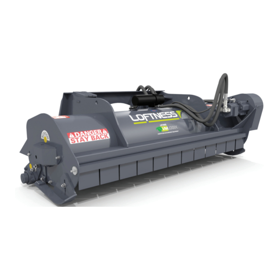
- Page 1 Hydraulic Flail Mower 60HM 72HM 90HM • • Owner’s Manual and Parts Book (Originating w/Serial Number 05-468) Model Number: Serial Number: Date of Purchase: N14800 Rev. K 04.09.19...
- Page 3 All Loftness products have a one (1) year limited warranty. The XLB10 Grain Bag Loader has a two (2) year limited warranty. If any Loftness product is used as rental equipment, or in a commercial application, the limited warranty period is for only 30 days from the delivery date to the original customers.
-
Page 5: Table Of Contents
Table of Contents Warranty Table of Contents Ordering Code Ordering Code ............. . .1 Hydraulic Flail Mower (Example) . - Page 6 Table of Contents Maintenance (Cont’d) Storage ..............18 End of the Season .
-
Page 7: Ordering Code
Ordering Code Ordering Code Hydraulic Flail Mower (Example) The ordering code will consist of two numbers (machine size), two letters (machine type), one number (hydraulic system), two numbers (motor GPM and PSI), and one letter (sheave/belt combination). An example for a Hydraulic Flail Mower of this type would be as shown below. - Page 8 Hydraulic Flail Mower OM...
-
Page 9: Introduction
Always use your model and serial number when products may result in changes to your equipment requesting information or when ordering parts. that may not be reflected in this publication. Loftness reserves the right to make product improvements to the Manual Storage machine at any time. -
Page 10: Hydraulic Flail Mower Features
Introduction Hydraulic Flail Mower Features • NEW - High Pressure Gear-type Motor (27-43 GPM up to 4300 PSI) • Standard Gear Motor (with or without Case Drain) (13-26 GPM up to 3400 PSI) • Heavy-duty, Bearing Block • 3-groove Banded Belt •... -
Page 11: Safety Instructions
Safety First Be certain all machine operators are aware of the dangers indicated by safety decals applied to the machine, and be certain they follow all safety decal Safety Alert Symbol instructions. Contact Loftness for safety decal replacement. This message alert... -
Page 12: Safety Rules
Safety Instructions Safety Rules attempting to operate the unit. Know how to stop the unit before starting it. These are general safety considerations. Additional • Repeated impact of the knives with hard objects can precautions may be necessary to operate your cause excessive wear and damage to the skid-steer machine in a safe manner. -
Page 13: Operation Safety
Safety Instructions Safety Rules (Cont’d) DANGER: Safety Instructions for Operation and DANGER: Before leaving the operator’s position for • Maintenance (Cont’d) ANY reason or allowing anyone near the flail mower, always exercise the following the “Mandatory Shut- Down Procedure” on page 5. •... -
Page 14: Hydraulic Safety
Safety Instructions Safety Rules (Cont’d) DANGER: Operation Safety (Cont’d) • Never get off skid-steer while it is in motion! • Rotating driveline! Personal injury or death can result • Due to the possible danger of flying debris, impact- from entanglement! resistant shielding must be provided for the operator. -
Page 15: Safety Decal Locations
AND THOROUGHLY UNDERSTAND THE CONTENTS OF THE OPERATOR'S MANUAL. Part No. 203264 NOTE: IF YOU DO NOT HAVE AN OPERATOR'S MANUAL, CONTACT YOUR DEALER OR LOFTNESS SPECIALIZED EQUIPMENT 650 SOUTH MAIN HECTOR, MN 55342 WARNING 1-800-828-7624 FAILURE TO FOLLOW SAFETY, OPERATING, AND Rotating parts hazard. -
Page 16: Hydraulic Flail Mower Identification
Safety Instructions Hydraulic Flail Mower Identification Step Drive Belt Drive Sheave Rotor Sheave Flippers Hydraulic Motor Overhung Load Adapter Drive Shield Skid Shoe (removed) (left side) Manual Holder Right Side Rotor Bearing Cover Universal Skid Steer Mount Skid Shoe (right side) Deflector Roller with Scraper... -
Page 17: Set-Up And Operating Instructions
Connect hydraulic quick-couplers from flail mower to auxiliary hydraulic outlets on loader. The Loftness Hydraulic Flail Mower can be attached to any skid-steer with an auxiliary hydraulic system of 13- 40 GPM, which has a standard universal skid steer hitch. -
Page 18: Operation
Various mowing conditions, and desired finished-cut appearance, will determine proper ground speed. WARNING: Do not operate the mower above the rated RPM. Check with your Loftness dealer to be sure your mower is set-up with the correct hydraulic motor to match the hydraulic flow (Gallons Per Minute) of your loader. -
Page 19: Maintenance
Maintenance General Maintenance Lubrication To ensure efficient operation, you should inspect, Grease Points Location lubricate, and make necessary adjustments and repairs at regular intervals. Parts that are starting to show The operation and component lifetimes of this machine wear should be ordered ahead of time, before a costly are very dependent on regular and proper lubrication. - Page 20 Maintenance Lubrication (Cont’d) Grease Points Location (Cont’d) Location: Roller bearings - right side (4) left side (5). Every 8 hours of operation. Interval: Location: Rotor bearings - right side (1) left side (2). Every 8 hours of operation. Interval: Location: Belt idler bracket (3). Remove Drive Shield for access.
-
Page 21: Adjusting Height Of Cut
Maintenance Adjusting Height of Cut This procedure should be performed on a level surface with mower mounted on tractor. The flail mower uses slotted adjustments on the rear roller to allow an infinite cutting height adjustment from 0 to 4-1/2". To adjust the height of cut: Set bucket tilt cylinders to carry flail mower level from front to rear. -
Page 22: Knife Reversal Or Replacement
Maintenance Knife Reversal or Replacement: Belt Removal/Installation When the knives become dull, they should be reversed Disconnect or turn off all power to the flail mower. to extend the usable life. When both sides of the knives become dull, the set must be replaced. Always replace DANGER: Failure to turn off power to the flail knives as a set, either when broken or dull. -
Page 23: Sheave Removal
Maintenance Sheave Removal To increase gripping force, hammer face of bushing using drift or sleeve. NOTE: Refer to parts breakdown “Belt and Sheaves” NOTE: Do not hit bushing directly with hammer. on page 29 for illustrated parts listing. 10. Re-torque screws after hammering. Drive Sheave Removal 11. -
Page 24: Rotor Removal (Mower In Operating Position)
Maintenance Rotor Removal (Mower in Operating Storage Position) End of the Season The belt and sheave should be removed with the mower • Clean entire mower thoroughly. in operating position, but the procedures for rotor removal and installation are greatly simplified if the machine is •... -
Page 25: Troubleshooting
Maintenance Troubleshooting WARNING: When high pressure fluid escapes,it can be almost invisible, yet have enough pressure to penetrate the skin and enter the blood stream. Never attempt to use hands to search for suspected oil leak. If injured by escaping fluid, consult a doctor at once! Serious reaction or infection can occur if proper medical treatment is not obtained immediately. -
Page 26: Motor & Sheave Selection Chart
Maintenance Motor & Sheave Selection Chart FIXED DISPLACEMENT LOFTNESS ROTOR TOP SHEAVE (LOFTNESS NUMBER) DISPLACEMENT PART BOTTOM SHEAVE ( LOFTNESS NUMBER) MOTOR NUMBER NUMBER BELT LENGTH (LOFTNESS NUMBER) MODEL CODE 1919 6.8 Top Sheave N11421 1.97ci N10908 5.4 Bottom Sheave N34050 2068 32.28cc... -
Page 27: Parts Identification
Parts Identification PARTS IDENTIFICATION Hydraulic Flail Mower OM... -
Page 28: Rotor
Parts Identification Rotor To order a complete 60" rotor assembly with Knives (items 13, 14, 15, 16, 17), use part number N11056. To order a complete 72" rotor assembly with Knives (items 13, 14, 15, 16, 17), use part number N10963. To order a complete 90"... - Page 29 Parts Identification Rotor QTY. PART # DESCRIPTION 4245 BOLT, 1/2"-20 UNF X 1-3/4" LG HEX HD GR 8 N30233 BEARING, 1-3/4" DODGE 4-BOLT FLANGE 4250 NUT, 1/2" UNC STD 4155 WASHER, 1/2" LOCK 4012 BOLT, 1/2" UNC X 1-1/4" LG HEX HD GR 5 7505 PLATE, ANTI-WRAP (FLAIL BEARING) 4436...
-
Page 30: Roller
Parts Identification Roller 3 3 5 The hardware requirements for items 15, 16, 17 and 18 varies according to deflector length. The quantities per length are as follows: 60" Deflector - 9 ea. 72" Deflector - 11 ea. 90" Deflector - 17 ea. Hydraulic Flail Mower OM... - Page 31 Parts Identification Roller QTY. PART # DESCRIPTION 4250 NUT, 1/2" UNC STD 4155 WASHER, 1/2" LOCK 4438 NUT, STANDARD 5/8" GRD 8 4011 BOLT, 1/2" UNC X 1" LG HEX HD GR 5 4069 WASHER, 5/8" FLAT 4022 BOLT, 5/8" UNC X 2" LG HEX HD GR 5 4347 WASHER, 1-5/16"...
-
Page 32: Drive Shield, Bearing Cover, And Manual Holder
Parts Identification Drive Shield, Bearing Cover, and Manual Holder Manual Holder Bearing Cover Drive Shield QTY. PART # DESCRIPTION 7530 SHIELD, BELT 7529 PIN, BELT SHIELD 4012 BOLT, 1/2" UNC X 1-1/4" LG HEX HD GR 5 N16161 GUARD, RIGHT BEARING 4155 WASHER, 1/2"... -
Page 33: Flippers And Skid Shoes
Parts Identification Flippers and Skid Shoes QTY. PART # DESCRIPTION N10958 FLIPPER, 90" FRONT N10958 FLIPPER, 72" FRONT N10958 FLIPPER, 60" FRONT 7508 ROD, 90" FLIPPER 7507 ROD, 72" FLIPPER N10991 ROD, 60" FLIPPER 4375 PIN, 3/16" X 1" LG ROLL 7512 SHOE, RIGHT SKID 7511... -
Page 34: Belt Tightener
Parts Identification Belt Tightener QTY. PART # DESCRIPTION 4105 ZERK, SCREW-IN GREASE 4157 WASHER, 1" ID THIN SPACER 4158 WASHER, 1" ID THICK SPACER 4325 PIN, COTTER 3/16" X 1-1/2" 4252 BOLT, 5/8-11 UNC X 4-1/2" LG HEX HD GR 5 7528 SPACER, 5/8"... -
Page 35: Belt And Sheaves
Parts Identification Belt and Sheaves QTY. PART # DESCRIPTION 8403 BELT, 3B X 51" GOODYEAR N11421 SHEAVE, TAPERLOCK 6.8 PD 3-BAND (Code “F”) N34043 SHEAVE, 3B X 6.2 TPL 2517 (Code “I”) N34042 SHEAVE, TAPERLOCK 6.08 PD 3-BAND (Code “B”) N34073 SHEAVE, 3B X 5.4 TPL 2517 (Code “G”) N34050... -
Page 36: Hydraulic Motor, 3400 Psi Without Case Drain (System 1, 13-26 Gpm Units)
Parts Identification Hydraulic Motor, 3400 PSI without Case Drain (System 1, 13-26 GPM Units) Pressure Tank NOTE: The Overhung Load Adapter (Item 3) is equipped with a special “high pressure mechanical seal”, eliminating the need for a case drain. Send the complete adapter back to the factory for all repairs. - Page 37 Parts Identification Hydraulic Motor, 3400 PSI without Case Drain (System 1, 13-26 GPM Units) QTY. PART # DESCRIPTION 4013 BOLT, 1/2" UNC X 1-1/2" GRADE 5 WASHER, 1/2" SAE FLAT GRADE 8 (For Motors N10908, 4068 N10909, and N10911) 4064 WASHER, FLAT 3/8"...
-
Page 38: Hydraulic Motor, 3400 Psi With Case Drain (System 2, 19-26 Gpm Units)
Parts Identification Hydraulic Motor, 3400 PSI with Case Drain (System 2, 19-26 GPM Units) Pressure Tank Case Drain * To order a complete Flail Check Valve ** For parts breakdown of Item 4 (N16416), see page 36. Kit (Items 12, 13, 14, 15, 16, 17), use part number N11366. - Page 39 Parts Identification Hydraulic Motor, 3400 PSI with Case Drain (System 2, 19-26 GPM Units) QTY. PART # DESCRIPTION 4013 BOLT, 1/2" UNC X 1-1/2" GRADE 5 4068 WASHER, 1/2" SAE FLAT N16574 ADAPTOR, OVERHUNG LOAD 1/4 N16416 ADAPTER, OVERHUNG LOAD MOTOR #2 (Includes Item 7) N14158 GASKET (Included with Item 4) N20280...
-
Page 40: Hydraulic Motor, 4300 Psi (System 2, 27-43 Gpm Units)
Parts Identification Hydraulic Motor, 4300 PSI (System 2, 27-43 GPM Units) Tank Pressure (Item 13 - N11366) * To order a complete Flail Check Valve Kit (Items 17, 18, 19, 20, 21, 22) use Item 13 (part number N11366). See Detail A ** For parts breakdown of Item 4 (N16416), see page 36. - Page 41 Parts Identification Hydraulic Motor, 4300 PSI (System 2, 27-43 GPM Units) QTY. PART # DESCRIPTION N16574 ADAPTOR, OVERHUNG LOAD 1/4 4013 BOLT, 1/2" X 1-1/2" GRADE 5 4068 WASHER, 1/2" SAE FLAT N16416 ADAPTER, OVERHUNG LOAD MOTOR #2 N31534 BOLT, 1/2 X 1-1/4 12 PT GRD8 N16472 WASHER, 1/2 NORDLOCK N34676...
-
Page 42: Overhung Load Adapter (N16416)
Parts Identification Overhung Load Adapter (N16416) QTY. PART # DESCRIPTION N14151 SEAL, FRONT (1.50" I.D. X 2.13" O.D. X .312" THK) N14152 CUP, BEARING N14153 CONE, BEARING N14154 SHAFT N14156 RING, RETAINING N14157 SEAL, REAR (55MM X 90MM X 10MM) N14158 GASKET Hydraulic Flail Mower OM... -
Page 43: Machine Decals And Signs
CONTENTS OF THE OPERATOR'S MANUAL. NOTE: IF YOU DO NOT HAVE AN OPERATOR'S Part No. 4334 MANUAL, CONTACT YOUR DEALER OR LOFTNESS SPECIALIZED EQUIPMENT 650 SOUTH MAIN HECTOR, MN 55342 1-800-828-7624 FAILURE TO FOLLOW SAFETY, OPERATING, AND MAINTENANCE INSTRUCTIONS COULD RESULT Part No. - Page 44 Parts Identification Machine Decals and Signs (Cont’d) Part No. N24822 Part No. N24823 Part No. N13721 Part No. N13517 Part No. 4138 FEMA Part No. 4137 Part No. N33105 Part No. N28576 Part No. N26973 Hydraulic Flail Mower OM...
-
Page 45: Appendix
Appendix Specifications DESCRIPTION FLAIL MOWER Cutting Width 60 in. (152.4 cm) 72 in. (182.9 cm) 90 in. (228.6 cm) Cutting Height 0 to 4-1/2 in. (roller adjustment) Operating Capacity 1 in. (2.54 cm) Continuous Motor High Pressure Gear-type Motor, 27-43 GPM up to 4300 PSI Gear-type Motor, 13-26 GPM up to 3400 PSI Rotor Bearing Heavy Duty 1-3/4 in. -
Page 46: Dimensions
Appendix Dimensions FLAIL MOWER DESCRIPTION 60HM 72HM 90HM Cutting Width (A) 60 in. (152.4 cm) 72 in. (182.9 cm) 90 in. (228.6 cm) Overall Width (B) 72 in. (182.9 cm) 84 in. (213.4 cm) 102 in. (259.1 cm) Cutting Depth (C) 42.75 in. -
Page 47: Torque Specifications
Appendix Torque Specifications Inches Hardware and Lock Nuts TORQUE CHARTS Minimum Hardware Tightening Torques Normal Assembly Applications (Standard Hardware and Lock Nuts) Nominal Unplated Plated Unplated Plated Unplated Plated Grade Grade Size W / ZnCr W / ZnCr W / ZnCr W / Gr. -
Page 48: Metric Hardware And Lock Nuts
Appendix Torque Specifications (Cont’d) Metric Hardware and Lock Nuts TORQUE CHARTS Minimum Hardware Tightening Torques Normal Assembly Applications (Metric Hardware and Lock Nuts) Class 5,8 Class 8,8 Class 10,9 Lock nuts Nominal Unplated Plated Unplated Plated Unplated Plated Class 8 Size W / ZnCr W / ZnCr... - Page 50 Loftness Specialized Equipment, Inc. 650 So. Main Street • PO Box 337 • Hector, MN 55342 Tel: 320.848.6266 • Fax: 320.848.6269 • Toll Free: 1.800.828.7624 Printed in USA © Loftness 2019...
Need help?
Do you have a question about the 60HM and is the answer not in the manual?
Questions and answers