Advertisement
Quick Links
---------------------------------------------------------------------------------------------------------------------------------------------------------------
CHAPTER 1 INTRODUCTION
§
1-1 Welcome
The BDI-2006 weighing indicator is a model of breakthrough high resolution.
The purpose of designing BDI-2006 is to perform quick and accurate controls
Please contact us immediately for further services if needed.
E-mail:
bde.com@msa.hinet.net
§
1-2 Features
BDI-2006 Weighing Indicator & Controller Features:
1/16,000 displayed resolution (Max. 1/ 60,000 depending on load cell quality &
performance). Internal Resolution 1,000,000, A/D Conversion rate 120 times/
Sec.
Watchdog virtually eliminates malfunctions that associated with
computerized equipment or software failure.
Full Digital Calibration makes setting ZERO and SPAN Calibration an easy
task.
Drives up to 8 parallel connecting load cells.
8k bytes SRAM with Li-battery backup. Information will not disappear even
power failure.
The settings of function and weighing parameters are all stored in the EEPROM,
with storage duration over 40 years.
Important values and parameters can have storage backup.
Users can adjust the intensity of digits filter to avoid mechanical vibration that
caused by external environments to achieve high-speed and accurate
measurement.
Set point codes can store up to 100 sets of: Final, SP1, SP2, Free Fall, HI, LO.
Automatic Free Fall Compensation provides closer tolerance and precise
weighing.
8 Set of control Input: ZERO Input, TARE Input, Tare reset, Start
batch,Abort batch, Print Accumulator, Print Input, Clear, ACC. &
COUNT.
8 Set of control Output: ZERO Band output, SP1 output, SP2 Output, (Final-Free
Fall) output, HI output, LO output, Final Output, MD/Error output.
Standard Serial Output (20mA Current Loop) for remote display.
Optional printer interface can automatically print or output data includes:
time, set point code, serial number, weight, and unit.
§
1-3 Items In Carton
The carton in which the BDI-2002 is delivered contains: 1. Indicator. 2. Accessory pack (In
bag). 3. Electric Cord. 4. This manual.
---------------------------------------------------------------------------------------------------------------------------------------------------------------
BENEDICTION ENTERPRISE CO., LTD, TAIWAN
Web Site:
http://www.bde.com.tw
1
date,
BDI-2006
Advertisement

Summary of Contents for BDE BDI-2006
- Page 1 CHAPTER 1 INTRODUCTION § 1-1 Welcome The BDI-2006 weighing indicator is a model of breakthrough high resolution. The purpose of designing BDI-2006 is to perform quick and accurate controls Please contact us immediately for further services if needed. E-mail: bde.com@msa.hinet.net Web Site: http://www.bde.com.tw...
- Page 2 To connect your load cell to the weighing Indicator use a six-wire cable with shield-connect the wires as indicated above. If the BDI-2006 is located near the Load Cells (Within five meters or a few yards) you may use a 4-wire cable with shield, but first connect screws 1&2 and 3&4 with independent jumper leads.
- Page 3 Do not bind these cables together as it could result in cross-talk interface. Please also keep them away from AC power cables. § 2-4 Front and Rear Panel Dimensions Front Panel of BDI-2006 Rear Panel of BDI-2006 Side View of BDI-2006 Mounting Cut for BDI-2006...
- Page 4 Max. Load Cell Input Voltage ±(0.2μV + 0.001% of Dead Load)/℃ TYP ZERO Temperature Comp. ± 0.001% ℃ TYP SPAN Temperature Comp. 1/16,000 (BDI-2006 Resolution can reach 1/60,000 depending on Max. Resolution load cell quality & performance). § 3-2 General ◎...
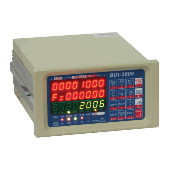
- Page 5 BENEDICTION ENTERPRISE CO., LTD, TAIWAN --------------------------------------------------------------------------------------------------------------------------------------------------------------- *3-3-2 BDI-2006 Front Panel Description ◎ DIGIT / LED LIGHT SECTION BDI-2006 Main Display﹝Green Tube﹞ 3 Column, 7-segment,8-digit displays the weight, with dots. ×1、×2、×5、×10、×20、×50 Minimum Division Maximum Display +800450 〝—〞minus sign Under ZERO Indicator 〝ZERO〞●LED Light...
- Page 6 BENEDICTION ENTERPRISE CO., LTD, TAIWAN --------------------------------------------------------------------------------------------------------------------------------------------------------------- ◎ KEY SECTION BDI-2006 SET MODE Accumulation WEIGHT WHEN Mode MODE SETTING Final / F1 / 1 Set Finish Weight Set pre-tare Unused Number “1” SP1 / F2 / 2 Set set-point one value Print Unused Number “2”...
- Page 7 Gross Weight, NET Weight, TARE Weight Stream / Stable and auto print / Manual Print Mode / F 203 Output Mode Accumulate and Print / Command Mode Output Format Sending without Set point Code / Sending with set point Code F 204 --------------------------------------------------------------------------------------------------------------------------------------------------------------- BDI-2006...
- Page 8 F 500 Analog Output Data Output 4~20 mA / Output 0~+10 V F 501 Output Mode Same as display / Gross data / NET data Loss-in-weight Absolute Not read Absolute Value / BDI-2006 reads Absolute F 502 Value Value Output current when F 503 0.0mA through 9.99mA (Initial 0.40mA)
- Page 9 Display Free Fall Value Panel Key Display Free Fall Value Display Hi Panel Key Display Hi limit Value limit Value Panel Key Display Lo limit Value Display Lo limit Value ※Please refer to chapter 7 about Control I/O and OP-02 --------------------------------------------------------------------------------------------------------------------------------------------------------------- BDI-2006...
- Page 10 4-1 System Check A system check should be run: after initial installation, after moving your BDI-2006, after connecting or disconnecting an attachment from the Rear Panel and as means of locating any unexplained system error. An occasional self-check to make sure everything is working properly is a good maintenance practice as well.
- Page 11 5 Oz ± 10% of weighing platform Full ● Capacity ± 20% of weighing platform Full F002 Display Update Rate Capacity 10 10 Times/Sec ± 30% of weighing platform Full ● 20 20 Times/Sec Capacity 40 40 Times/Sec --------------------------------------------------------------------------------------------------------------------------------------------------------------- BDI-2006...
- Page 12 2 GROSS Weight 1 Sending with set point Code 3 NET Weight 4 TARE Weight GROSS Weight, Weight, TARE Weight FC01 Output Mode ● 1 Stream 2 Stable and auto print 3 Manual Print Mode 4 Accumulate and Print --------------------------------------------------------------------------------------------------------------------------------------------------------------- BDI-2006...
- Page 13 BCD Input Error Serial Input F107 Automatic Free Fall Compensation Memory of Automatic Free F108 Fall Compensation value Please enter 6 digit free fall compensation Not memory value within effective range ● Initial “000.000”--- Free Fall OFF Memory --------------------------------------------------------------------------------------------------------------------------------------------------------------- BDI-2006...
- Page 14 Latest data “ t “ TARE Print on all , Weight according to F001 GROSS Weight, NET Weight, Print on all “ g “ TARE Weight GROSS Weight, NET Weight, Print on all “ t “ TARE Weight Initial --------------------------------------------------------------------------------------------------------------------------------------------------------------- BDI-2006...
- Page 15 NET Weight F 502 Loss-in-weight Absolute Value F 506 Output Volt at Full Capacity 0 Not read Absolute Value -2.5V through +59.9V BDI-2006 reads Absolute ●Initial 10.0 V Value Output current when display F 503 ZERO 0.0mA through 9.99mA ●Initial 4.0mA...
- Page 16 STEP 4: Use the ▲or▼key to choose d-CAL. Please press the key. ﹝1﹞Setting Minimum Division 1 shows the smallest division. Use the ▲ or ▼ The display of di key to move through the available divisions.﹝1、2、5、10、20、50﹞. Press the key to set the minimum division. --------------------------------------------------------------------------------------------------------------------------------------------------------------- BDI-2006...
- Page 17 F000 will subject to change if 1,2,3,or 4 key been pressed) Press key CAP →010.000(Blinking) 020.000(Blinking) 2,0,0,0,0 Press Press key ZERO Press key …… → SPAN Press key 000.000(Blinking at the latest decimal) Place 20kg Calibration Mass, 020.000 Press key …… → --------------------------------------------------------------------------------------------------------------------------------------------------------------- BDI-2006...
- Page 18 C.Err 9: The maximum, capacity has been wrongly entered as a value smaller than 100. Check Resolution Table. C.Err 10 The maximum, capacity has been wrongly entered as a value greater than 800,000. Check the load cell specification or load cell failure. --------------------------------------------------------------------------------------------------------------------------------------------------------------- BDI-2006...
- Page 19 ------------ 1∕14000 700,000 ------------ ------------ ------------ ------------ ------------ 1∕15000 750,000 ------------ ------------ ------------ ------------ ------------ 800,000 ------------ ------------ ------------ ------------ ------------ 1 / 16,000 ☆ BDI-2006 Display Resolution may reach 1/60,000. (Depends on load cell quality and performance). --------------------------------------------------------------------------------------------------------------------------------------------------------------- BDI-2006...
- Page 20 After enter key, a 〔 〕 will show on the screen. Please press the key you wish to disable. The screen will show the key’s number. BDI-2006 will inquire if you want to lock or unlock the key: 〔00〕u or L (Key number 〔00〕: Unlock or Lock the key).
- Page 21 4-7 SYSTEM INITILAIZE Re-install resets the BDI-2006 to the initial factory settings. Use Re-install only if you want to return Function, Set Point or Calibration to their initial settings. STEP 1: Turn the Power Switch OFF on the Rear Panel, and slide SET switch to the set side.
- Page 22 G 0.000 Press DISP MODE key until the screen displays G/T/N mode. Press key, -CODE- will blink. Choose the code number you wish to T 0.000 clear value, and press key to finish. N 0.000 --------------------------------------------------------------------------------------------------------------------------------------------------------------- BDI-2006...
- Page 23 ZERO Band Output will come ON -signifying the Weighing Hopper is empty. Closed the Weighing Hopper Discharge Gate by using the ZERO Band (Pin 13) Output ON signal. 10. You are now ready for your next batching event. --------------------------------------------------------------------------------------------------------------------------------------------------------------- BDI-2006...
- Page 24 11. If the GROSS weight of the Weighing Hopper is below the ZERO Band (Pin 13), the ZERO Band Output will be ON. The ZERO Band Output will refill Weighing Hopper if needed. 12. Ready for next batching event. --------------------------------------------------------------------------------------------------------------------------------------------------------------- BDI-2006...
- Page 25 Start signal is received, then: (1) SP 1, SP 2 and Free signals will go OFF, and Gates will be closed. (2) Batch Finish and Data Output signals will be sent. (3) NET Weight data will be accumulated. --------------------------------------------------------------------------------------------------------------------------------------------------------------- BDI-2006...
- Page 26 Start signal is received, then: (1) SP 1, SP 2 and Free signals will go OFF, and Gates will be closed. (2) Batch Finish and Data Output signals will be sent. (3) NET Weight data will be accumulated. --------------------------------------------------------------------------------------------------------------------------------------------------------------- BDI-2006...
- Page 27 ZERO Band Output will come ON which signifying the Weighing Hopper is empty. Closed the Weighing Hopper Discharge Gate by using the ZERO Band (Pin 13) Output ON signal. 13. You are now ready for your next batching event. --------------------------------------------------------------------------------------------------------------------------------------------------------------- BDI-2006...
- Page 28 7-1 I/O INTERFACE CODE INPUT Pin Pin Name Pin Pin Name 1×1 2×10 2×1 4×10 4×1 8×10 Common 8×1 1×10 ◎ Control I / O Input BDI-2006 The width of these inputs are at least 200m sec Output --------------------------------------------------------------------------------------------------------------------------------------------------------------- BDI-2006...
- Page 29 NET weight will be accumulated. Customer Program- control When Pin 21 is short-circuit to COM1, Mode Automatic Free Fall BDI-2006 will estimate the free fall value for Compensation command (Pulse the next batch, and the NET weight will be input).
- Page 30 (1) 25 Pin D- Shape Name Pin 1 R ×D Pin 2 Pin 3 T ×D Pin 4 Pin 5 Pin 6 Pin 7 (2)9Pin D Shape Name Pin 2 TxD (Transmit Data) Pin 5 SG (Signal Ground) --------------------------------------------------------------------------------------------------------------------------------------------------------------- BDI-2006...
- Page 31 Parity Stop Bit 1 bit Output Code ASC II RS-422 R+>R- R+<R- Pin Assignments of RS-422: ◆ : Pin Connection RS-422 Name Name R+ R- 100Ω Frame Ground 54Ω Signal Ground T- Terminal T+ --------------------------------------------------------------------------------------------------------------------------------------------------------------- BDI-2006...
- Page 32 Format1(Data Update speed is the same as F002) C D , 0 1 , S T , N T , 0 2 ‧ 1 g Cr Lf CODE Code Header 1 Header 2 Data(8 digits in length) UNIT number --------------------------------------------------------------------------------------------------------------------------------------------------------------- BDI-2006...
- Page 33 SS ×× Cr Lf BDI-2001B will send back SET POINT values until totally <SET SETPOINT> receive SET POINT values. RS ×× Cr Lf BDI-2001B receives signal “RS xx Cr Lf ”, <READ SET POINTS> and read xx set point value. --------------------------------------------------------------------------------------------------------------------------------------------------------------- BDI-2006...
- Page 34 1 2 3 4 5 6 1 2 3 4 5 6 1 2 3 4 5 6 1 2 3 4 5 6 1 2 3 4 5 6 Cr Lf HI HH GO LO LL ※SA Cr Lfformat ZERO *FOR RS-485: Please set F205 and place @XX in front of commands. For example: @XXRCrLf. @XXTCrLf. --------------------------------------------------------------------------------------------------------------------------------------------------------------- BDI-2006...
- Page 35 Same as display Gross data NET data TARE F 400 Data type data Stream Stable and print Manual print mode F 401 Output Mode Accumulate and print Positive Logic Negative Logic F 402 Output Logic --------------------------------------------------------------------------------------------------------------------------------------------------------------- BDI-2006...
- Page 36 ※ Please add a pull-up resistance if 2×10000 / Decimal Point 2 connected to a TTL LOGIC. 4×10000 / Decimal Point 3 8×10000 / Decimal Point 4 1×100000 47 Hi=Overload 2×100000 48 4×100000 49 PRN 1 8×100000 50 / Busy(input) BDC OUTPUT LAYOUT: --------------------------------------------------------------------------------------------------------------------------------------------------------------- BDI-2006...
- Page 37 When Output at Full Scale is set at 36mA, and Output Current at Display ZERO is set at 4mA, then at 1/2 Capacity (5000kg) the Output Current will be 20mA. ※ NOTE: The Maximum Output will be saturated at 22mA. Output Circuit: Inside OP-05 ※Max. resistance R≦500Ω --------------------------------------------------------------------------------------------------------------------------------------------------------------- BDI-2006...
- Page 38 NOTE: The Maximum Output will be saturated at 11.25. § 7-6 Remote Set Point Unit: Final Weight OP-07 Please refer to F700 in § 4-2 Functions Pin Assignment: Description Description Finish 10 Finish 10 Finish 10 Finish 10 Finish 10 SHIELD SHIELD --------------------------------------------------------------------------------------------------------------------------------------------------------------- BDI-2006...
- Page 39 PIN 9 Number of Pins:8. PIN 8 PIN 7 Input Common Pin:COM1 PIN 6 Output(OUT): Number of Pins:8. Type:for RELAY. Max. Load:24~280VAC, 3A (Only for AC) Output Common Pin:COM2 RELAY durance:About 100,000 Times. LED light will ON when work. --------------------------------------------------------------------------------------------------------------------------------------------------------------- BDI-2006...
Need help?
Do you have a question about the BDI-2006 and is the answer not in the manual?
Questions and answers