Advertisement
Quick Links
DESCRIPTION
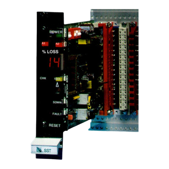
MODEL 5029 4-20 mA ANALOG INPUT MODULES
DESCRIPTION
The SST Model 5029 Analog Input Modules are used to monitor any process variable
that can be converted to the indust ry standard 4-20 Ma output signal. The analog
input on the module is completely isolat ed, so that it can be fed from a transmitter
that is referenced to + DC, -DC, ground, or f loating. Because this is a current loop,
other devices, such as a PLC input or a data acquisition syst em, may be connected
into the same loop w ithout aff ecting the Model 5029 indications. A 24 VDC out put,
derived from the redundant NOVA-5000 system pow er supplies, is provided for
pow ering the 4-20 mA transmitter associated w ith the field sensor. The module
features a digital readout indicating t he relative level of the sensed signal, plus tw o
alarm indicating circuit s w it h adjustable alarm levels. Field w iring to t he transmitter
is continuously supervised, and the module automatically performs a self -check
routine at regular intervals.
!
NOTE: The information in t his sect ion applies to all modules in t his series.
These modules are all elect rically identical, regardless of the actual
variable being sensed. The only dif ference betw een the various models is
the legend at the top of the nameplate (pressure, temperature, Halon
w eight, etc.), and the maximum level displayed on t he digital readout .
Application Caution
The Analog Input Module int erf aces
process management functions to
t he NOVA-5000 Cont rol System.
An alarm condition on the analog
module does not indicate a fire con-
dition. The outputs of the analog
module must not be used to ac-
tivate any fire alarm signal devices.
The analog modules should activate
separate and distinct signals f rom
the fire syst em.
LOGIC DIAGRAM
Figure 5029-1 show s, in simplified
f orm, t he int ernal logic in t he
Analog Input Module, and indicates
the terminal number assigned w ith
each.
DESIGN MANUAL
MODEL 5029 4-20 mA ANALOG INPUT MODULES
Figure 5029-1 Logic Diagram
December, 1994
5029-1
Advertisement

Summary of Contents for SST 5029
- Page 1 PLC input or a data acquisition syst em, may be connected into the same loop w ithout aff ecting the Model 5029 indications. A 24 VDC out put, derived from the redundant NOVA-5000 system pow er supplies, is provided for pow ering the 4-20 mA transmitter associated w ith the field sensor.
-
Page 2: Input/Output Connections
MODEL 5029 4-20 mA ANALOG INPUT MODULES INPUT/OUTPUT CONNECTIONS Figure 5029-2 show s the physical arrangement of t he 16 terminals associated w ith the Analog Input Module. Each of the available signals is described below. Alarm Relay Outputs — terminals 1 through 6 These are NOVA-5000 St andard Relay Output s that operat e w henever the signal level detected exceeds the alarm levels programmed int o t he module. - Page 3 120 V AC or DC w ith respect t o ground. Typical Wiring Diagram Figures 5029-3 and 5029-4 show the approved connect ions f or t he Model 5029 series modules. All installations should be made in conformance w ith these draw - ings.
- Page 4 MODULE SETUP INSTRUCTIONS MODEL 5029 4-20 mA ANALOG INPUT MODULES MODULE SETUP INSTRUCTIONS All NOVA-5000 modules are completely test ed and calibrat ed at the factory bef ore shipment. The follow ing adjustments are the only ones necessary before installing the module.
- Page 5 Module keying Bef ore installing each Model 5029 analog module into the w ired slot in the mount ing rack, be sure t hat t he snap in covers have been installed at keying locations 2 and 10 of the rack keying strip.
- Page 6 OPERATING INSTRUCTIONS MODEL 5029 4-20 mA ANALOG INPUT MODULES Alarms and faults are indicated as f ollow s: • When an alarm or f ault indication is f irst detected, the relevant indicat or lamp flashes. Most syst ems are w ired so that an audible alarm sounds at the same time.
- Page 7 OPERATING INSTRUCTIONS MODEL 5029 4-20 mA ANALOG INPUT MODULES off w hen t he input signal is near normal. If the f ull scale capability of t he module is 100, the display w ill start at 3. For 50 scale modules, display st art s at 2; for 20 scale modules, 1.
- Page 8 OPERATING INSTRUCTIONS MODEL 5029 4-20 mA ANALOG INPUT MODULES Isolate Lamp (yellow) This lamp indicat es t hat the Isolate sw itch is in the Isolat e (up) position. Isolate Switch This sw it ch is recessed behind t he panel and requires a small screw driver to operate it.
- Page 9 CALIBRATION MODEL 5029 4-20 mA ANALOG INPUT MODULES CALIBRATION The module is shipped w ith the zero and span pre-set so that an input of 4.0 mA corresponds to a reading of “ 0" and 20.0 mA corresponds to full scale on the digital readout .
- Page 10 Blank Page...
Need help?
Do you have a question about the 5029 and is the answer not in the manual?
Questions and answers