Table of Contents
Advertisement
Quick Links
Advertisement
Table of Contents

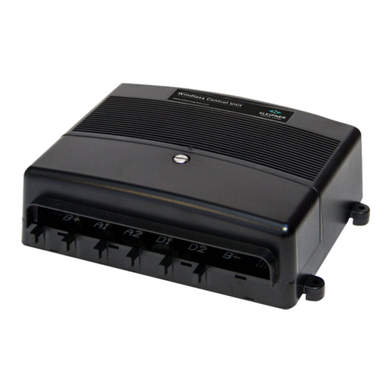
Summary of Contents for Sleipner ECU
- Page 1 User Manual Including Installation For External Control Unit DOCUMENT ID: SLEIPNER AS 1473 REVISION: P.O. Box 519 DATE: N-1612 Fredrikstad 2021 Norway LANGUAGE: www.sleipnergroup.com To download your language go to www.sleipnergroup.com...
-
Page 2: Table Of Contents
Configuring Windlass Type ............6 Fault codes ................6 Troubleshooting ................. 7 Installation Guide Measurements ................. 9 ECU Installation ..............10 Visual Wiring Diagram ............. 11 - 12 Spare Parts................13 Product Templates and Additional Resources ....13 Warranty Statement ............... 13... -
Page 3: Considerations And Precautions
IMPORTANT NOTICE S-LINK™ SYSTEM When installing an S-Link™ system DO NOT connect any other control equipment directly to the S-Link™ bus except original Sleipner S-Link™ products. Connecting third-party equipment must always be connected through a Sleipner-supplied interface product. Any attempt to directly control or connect into the S-Link™... -
Page 4: Features
• Careless use can cause damage or injury! • Make sure to have good battery capacity, and keep the engine running windlass operation. • Sleipner Motor AS is not responsible for injury caused by the use of our windlass systems. Technical Specifi cations... -
Page 5: Operations
Operations MC_0401 1473 2021... -
Page 6: Configuring Windlass Type
Confi guring Windlass Type MC_0405 Press and hold “Confi g” button for 3 seconds, until Power and Fault LED starts blinking. Press “Confi g” button to cycle through types, until the Mode LEDs show the correct pattern. The controller returns to normal operation after 3 seconds of inactivity Verify that the pattern shown is correct. -
Page 7: Troubleshooting
Troubleshooting MC_0401 IMPORTANT Main switch/ braker must be disconnected whenever working on the windlass mechanical parts FAULT SYMPTOM FAULT CODES/STATUS SOLUTION Windlass does not operate "Power" LED not lit Check: Main switch/breaker is engaged. Check battery fuses. Visually inspect cables and verify that terminals are tight. Measure battery voltage. -
Page 8: Installation Guide
Installation Guide DOCUMENT ID: SLEIPNER AS REVISION: P.O. Box 519 DATE: N-1612 Fredrikstad Norway LANGUAGE: www.sleipnergroup.com 1473 2021... -
Page 9: Measurements
Measurements MC_0399 Measurement Measurement description code mm inch ESI Length 7.48 Additional ESI Length 8.35 ESI Height ESI Width Additional ESI Width Distance of attachment holes (width) 7.87 Distance of attachment holes (height) 3.74 MG_0330 1473 2021... -
Page 10: Ecu Installation
- The control unit must be mounted with the the cables protruding downwards. Mount the ECU to a dry surface area. Ensure attached cables will protrud downwards.(NB: The unit has mounts that ensures space between the unit and it’s mounting surface. This to avoid condensation to enter the unit. It also ensures proper ventilation of the enclosure.) Remove the cable cover plate. -
Page 11: Visual Wiring Diagram
Visual Wiring Diagram Control panel Control panel (Altern. control panel) 86-00002 86-08950 86-08955 Control box 150800 config Opt. Side-power 150810 remote receiver 4-lead Main circuit Sidepower breaker/fuse control cable Connec�on to control box : Connec�on to control box (without Sidepower control cable) : Black to terminal V- white to terminal N Blue to terminal N... - Page 12 Visual Wiring Diagram Connecting the motor and battery cables on Maxi - Connect the four motor cables to the Terminals masked A1/A2/D1/D2. - Connect supply cable from battery negative to the Terminal marked B-. - Connect supply cable from breaker/fuse to the Terminal marked B+. Connect beaker/fuse to battery main switch. - Tighten all terminals properly, with a maximum torque of 5Nm.
-
Page 13: Spare Parts
10. This warranty gives you specific legal rights, and you may also have other rights which vary from country to country. Patents MC_0024 At Sleipner we continually reinvest to develop and offer the latest technology in marine advancements. To see the many unique designs we have patented visit our website www.sleipnergroup.com/patents 1473... - Page 14 Notes MC_0037 ..............................................................................................................................................................................................................................................................................................................................................................................................................................................................................................................................................................................................................................................................................................................................................................................................................................................................................................................................................................................................................................................................................................................................................................................................................................................................................................................................................................................................................................................................................................................................................................................................................1473 2021...
- Page 15 Notes MC_0037 ..............................................................................................................................................................................................................................................................................................................................................................................................................................................................................................................................................................................................................................................................................................................................................................................................................................................................................................................................................................................................................................................................................................................................................................................................................................................................................................................................................................................................................................................................................................................................................................................................................1473 2021...
- Page 16 © Copyright Sleipner Motor AS, 2021 The information given in the document was correct at the time it was published. However, Sleipner Motor AS can not accept liability for any inaccuracies or omissions it may contain. Continuous product improvement may change the product specifi...


Need help?
Do you have a question about the ECU and is the answer not in the manual?
Questions and answers