Table of Contents
Advertisement
Advertisement
Table of Contents

Subscribe to Our Youtube Channel
Related Manuals for Welch Allyn TM262 Auto Tymp


Summary of Contents for Welch Allyn TM262 Auto Tymp
- Page 1 Audio Menu Service Manual Operating Instructions...
-
Page 2: Table Of Contents
Contents Section 1—Introduction Instrument Description ..........1 Tympanometry and Gradient ........1 1.2.1 Tympanometry ............1 1.2.2 Gradient ..............2 Screening Acoustic Reflex ..........3 Manual Audiometry ............4 Section 2—Installation Unpacking and Inspection ..........5 Probe Indicators ............5 Front Panel Controls and Indicators ...... - Page 3 3.7.6 Exit Program Mode ..........30 Tympanometry Only Mode ......... 31 3.8.1 Exit Tympanometry Only Mode ....... 32 Tympanometry and Ipsilateral Reflex Mode ....32 3.9.1 Programming Ipsilateral Acoustic Reflex Test Frequencies ......33 3.9.2 Exit Tympanometry/Reflex Mode ......34 3.10 Audiometry Test Sequence (Models with Audiometer Only) ........
-
Page 4: Section 1-Introduction
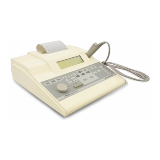
Section 1—Introduction 1.1 INSTRUMENT DESCRIPTION The TM 262 Auto Tymp is a versatile combination instrument which provides testing capability for tympanometry alone, tympanometry combined with screening acoustic reflex measurements, and manual audiometry. Two different versions are available to meet your individ- ual testing needs. -
Page 5: Gradient
The point on the tympanogram which represents the point of maximum compliance (admittance) is the compliance peak of the tympanogram. The air pressure (pressure at the peak) where this compliance peak occurs approximates the pressure within the middle-ear system, since maximum mobility is only possible when there is little or no pressure difference between the ear canal and the middle-ear space. -
Page 6: Screening Acoustic Reflex
The TM 262 Auto Tymp determines tympanometric width (gradient) by measuring the pressure interval at one-half of the peak height. Differ- ing peak widths can point to different middle-ear conditions, even when peak height and pressure are within normal range. For example, middle- ear effusion brought on by secretory otitis media might result in an increased tympanogram width and, therefore, an increased gradient value. -
Page 7: Manual Audiometry
detectable for each patient tested. However, the TM 262 Auto Tymp automatically presents the stimulus in a very definite stimulus intensity sequence. This preset intensity sequence may start at a level above an individual’s acoustic reflex threshold level. Since the TM 262 uses a hand-held probe, noise from hand motion can be detected by the in- struments circuitry. -
Page 8: Section 2-Installation
Inventory the accessories in Table 2-1. If any accessories are missing or damaged, notify your Welch Allyn, Inc. distributor or the factory im- mediately. See page 60 for a listing of optional accessories. -
Page 9: Front Panel Controls And Indicators
2.3 FRONT PANEL CONTROLS AND INDICATORS The front panel controls and indicators are shown in Fig. 2-2 and are described follows. DATA PAGE PROG TRANSFER TYMP +10dB TYMP 500 Hz REFLEX 1000 Hz dBHL 2000 Hz 4000 Hz FIGURE 2-2: FRONT PANEL Power: Indicator is illuminated when the TM 262 is receiving power. - Page 10 +10 dB: Used to temporarily extend the audiometry intensity +10 dB range by 10 dB. When selected, a large plus sign appears on the display. F10 Save: During Audiometry mode, saves the threshold informa- tion (per frequency) on the display; during Program mode, selects a particular option;...
-
Page 11: Printer And Display
2.4 PRINTER AND LIQUID CRYSTAL DISPLAY (LCD) The printer cover can be removed to reload paper (see Figure 2-3). Section 2.6.1 (page 12) provides paper loading instructions. Printer Cover LCD display FIGURE 2-3: PRINTER COVER LOCATION 2.4.1 Liquid Crystal Display (LCD) The display indicates test mode, parameters for test and test results. - Page 12 FIGURE 2-5: Display format for Reflex test (results reported as “Yes” or “No”). FIGURE 2-6: Display format for Reflex test (results reported in “dB HL”). FIGURE 2-7: Display format for Reflex test (results reported in “dB HL” and also shown with a “tracing”). Tone Plus 10 dB HL presentation...
-
Page 13: Rear And Bottom Panel Labels/Connectors
2.5 REAR AND BOTTOM PANEL LABELS/CONNECTORS The rear panel labels and connectors are shown in Figure 2-9 and a description of each one follows. R2 R3 R4 FIGURE 2-9: REAR PANEL Company name, address, model, serial number and country of origin. Symbol denotes a Type B, Class II Product per IEC 878 as referenced in IEC 601 Standard. -
Page 14: Initial Setup
ON ( ). If both green and yellow lamps are still illuminated and you are certain that the probe is not occluded, contact the Welch Allyn Technical Service Department (see page 55). In the meantime, it is still possible to select the Audiometry mode (if purchased). -
Page 15: Loading The Paper
2.6.1 Loading The Paper Remove the printer cover (see Fig. 2-3 for location) by placing your fin- gers along the back edge of the printer and pulling upward on the cover. Cut the printer paper so that the leading edge of paper is straight across. Place the roll of paper inside the paper well so that the paper will unroll from the lower surface. -
Page 16: Pretest Tympanometry Checks
For your convenience, a test cavity is provided with your TM 262 Auto Tymp . This test cavity enables you to quickly verify the proper calibration of your unit. Welch Allyn, Inc. strongly recommends that you make this quick check a part of your daily routine. 2.7.1 Calibration... -
Page 17: Altitude Adjustment
But, many instrument operators prefer that their equipment give ECV values as they would appear at sea level. The altitude calibration mode allows the operator to adjust his/her Auto Tymp without the services of a qualified Welch Allyn Service Technician. - Page 18 TABLE 2-2: Altitude Correction Altitude Correction Altitude (ft.) Altitude Table (cm 0 to 1,500 2,000 to 3,500 2.1 ± 0.1 4,000 to 6,000 2.2 ± 0.1 6,500 to 7,500 2.3 ± 0.1 8,000 to 9,000 2.4 ± 0.1 9,500 to 10,000 2.5 ±...
-
Page 19: Pretest Audiometric Checks (Models With Audiometer Only)
Also, earphone sound enclosures are available from Welch Allyn as an optional accessory. If the person being tested is in the same room as the... -
Page 20: Biological Check
2.9 BIOLOGICAL CHECK To determine that your TM 262 is functioning properly, perform a daily check on a normal ear—your own if possible. This allows you to listen for the probe tone and the stimulus tone (during reflex) and determine if the air-pressure system is working properly. -
Page 21: Section 3-Operation
Section 3—Operation 3.1 EARTIP CARE After the eartip is removed from the probe, it can be washed with warm soapy water to remove cerumen. Use an alcohol swab to disinfect the eartips. Be sure that the eartips are completely dry before reuse. NOTE Eartips may crack or otherwise deteriorate if left submerged in alcohol for a long period of time. -
Page 22: The O-Ring
3.2.2 The O-Ring There is an O-Ring seated at the end of the threads on the probe. As a preventative maintenance measure, and to ensure that the nose cone of the probe unscrews easily, do not clean or remove the lubricant from this O-Ring. -
Page 23: The Probe Wire
3.2.3 The Probe Wire Inside the probe body there is a metal tube which contains a wire re- quired for cleaning purposes. Carefully remove this wire from the metal tube (see Figure 3-3). This will pull any cerumen out of the metal tube. Examine the wire for cerumen. -
Page 24: Paper Supply
Also, examine the earphone cord for cuts or tears in the covering shield and the earphone cushion for signs of damage. If either problem is no- ticed, the earphone cord or cushion should be replaced. Both parts are easily replaced without the need for recalibration. However, if the ear- phone receives shock damage or is replaced for any reason, the TM 262 will need to be recalibrated. -
Page 25: Tympanometry Testing Information
3.5 TYMPANOMETRY TESTING INFORMATION Perform a test on a normal ear each day to make certain that your TM 262 Auto Tymp is functioning properly. See Section 2.9 for details. 3.5.1 Helpful Hints Tympanometry and acoustic reflex testing can be performed at any age. - Page 26 Slip the appropriate size eartip onto the nose cone of the probe, mak- ing sure that eartip is flush against the surface of the nose cone (see Figure 3-5). Flush tip to nose cone FIGURE 3-5: Positioning the Eartip Before testing, clear any hair away from the ear and pull upward and back on the pinna.
-
Page 27: Audiometry Testing Information
The probe lamps will inform you of problems during testing as follows: Yellow lamp: The probe tip is occluded with cerumen or you are pressing too hard against the ear canal so that you have collapsed the canal at the tip of the probe. Green lamp: Still blinking—seal has not been obtained to initiate the test sequence. -
Page 28: Placement Of Earphones
* Reflex HL + Curve * Print—Audiogram Reflex HL only Print—Aud Table Reflex Yes/No * Normal Box ASHA * Prn Header Welch Allyn Normal Box Off Prn Header Off * Aud Range Normal Prn Header Custom Aud Range Narrow Note that these selections fall into five different groups of controls:... -
Page 29: Reflex Format
3.7.1 Reflex Format Reflex test results can be displayed and printed in these three ways: Reflex HL + Curve, Reflex HL Only, or Reflex Yes/No. Reflex HL + Curve (default) * Reflex Yes/No I (Ipsi) Frequency Intensity level I (Ipsi) Reflex HL Only I (Ipsi) Frequency... -
Page 30: Print Header Format
Allyn TM 262. To deselect the Welch Allyn header and select No Header or a Custom Header, use a similar procedure to that described above. With the Hz or Hz... -
Page 31: Audiometric Format During Printing
press the SAVE button to save your header in memory. The word SAVED will appear on the right-hand margin indicating that your header is now saved. The square cursor will reappear next to Prn Header Cus- tom. It is now possible to exit the program mode or to sequence on to the next user selection. -
Page 32: Normal Box Format
To change the default setting to tabular format, move the Hz button to position the cursor in front of the description PRINT—AUD TABLE. Next, select the SAVE button to save this format as the new default parameter. Note that the word SAVED ap- pears in the lower right-hand corner of the display to indicate that this new setting has been saved. -
Page 33: Audiogram Range
3.7.5 Audiogram Range All eleven frequencies are available during audiometry; however, the range can be abbreviated to eight frequencies. The default setting is Aud Range Normal. * Aud Range Normal * Aud Range Narrow 125 Hz thru 8000 Hz 500 Hz thru 6000 Hz To select the abbreviated frequency range, position the square cursor in front of the feature Aud Range Narrow. -
Page 34: Tympanometry Only Mode
3.8 TYMPANOMETRY ONLY MODE To do only Tympanometry, press the TYMP button. The display will TYMP immediately show the format for the tympanogram along with the sum- mary information headers: ECV, cm , daPa, and GR. The default scale for compliance is 1.5 cm . -
Page 35: Exit Tympanometry Only Mode
In addition to the tympanogram tracing, the screen displays the test summary data: Ear Canal Volume (ECV), the compliance peak in cm the pressure at the peak of the tympanogram in daPa, and the gradient (GR) as a pressure width value. The test results are automatically stored in a page of memory. -
Page 36: Programming Ipsilateral Acoustic Reflex Test Frequencies
aborted. If no other frequencies were selected for the test, the Tymp Reflex sequence ends here. The display will indicate the reflex test re- sult as described in Section 3.7. Note that the green lamp is no longer illuminated indicating that it is time to remove the probe from the ear. The same sequence is followed for each test stimulus selected, a maxi- mum of three different stimulus intensity levels are available for the test. -
Page 37: Exit Tympanometry/Reflex Mode
3.9.2 Exit Tympanometry/Reflex Mode To exit Tymp/Reflex Mode, select the Tymp Only or Audiometry Mode. Note that the appropriate screen appears on the display. 3.10 AUDIOMETRY TEST SEQUENCE (Models with Audiometer Only) To enter the audiometry mode, push the AUD button. -
Page 38: Screening Audiometry
tone of 1000 Hz, the normal intensity limit is 90 dB HL. When the inten- sity knob is rotated clockwise beyond the 90 dB HL maximum, the in- tensity value on the LCD flashes. This indicates that the normal intensity limit has been reached. -
Page 39: Threshold Audiometry
Select the ear to be tested with the RIGHT or LEFT button. Next, select the desired screening intensity by rotating the dB HL knob to the appropriate position. The American Speech Language and Hearing Asso- ciation recommends 20 dB HL as the screening level for school-aged children. -
Page 40: Exit Audiometry Mode
3.10.3 Exit Audiometry Mode To exit the audiometry mode, select the Tymp mode or the Tymp/Reflex mode. Note that the appropriate screen appears on the display. 3.11 TESTS IN MEMORY The Tymp and Tymp/Reflex test results are automatically stored in mem- ory once the test sequence ends. - Page 41 To print all tests in memory, press the PRINT ALL button. When PRINT ALL is selected, and two audiogram tests are stored in memory, they will combine under the following conditions: 1) There must be one left test and one right test sequentially stored in memory and 2) A left and right audiometric pair of tests will not be combined if they are separated in the memory by a tympanometry test.
-
Page 42: Section 4-Test Results
Section 4—Test Results 4.1 EAR CANAL VOLUME NORMAL As a general rule, values for ear canal volume should be between 0.2 and 2.0 cm . However, the normal values will vary with age and bone structure. With use, you will develop a feel for the appropriate values. ABNORMAL An ear canal value of less than 0.2 cm indicates an abnormal condition. -
Page 43: Pressure Peak
NOTE If the measured compliance value is less than 0.1 cm , the TM 262 Auto Tymp will print the letters NP next to the heading cm on the screen and printout. The letters “NP” indicate a poorly defined or flat tympanogram. The tympanogram may depict a very shallow peak. -
Page 44: Acoustic Reflex
ABNORMAL A high gradient value (greater than the high end of the normal range per age group) is indicative of middle ear effusion. The reduced compliance values and negative middle ear pressure characteristic of developing or resolving Otitis Media with Effusion (OME) will be manifested in a broad tympanogram with a large gradient value. -
Page 45: Audiometry
“E”. If an error code appears, repeat the operation that caused the error code to appear. If the error code appears for the second time, contact Welch Allyn with the exact error code number. 4.8 SAMPLE TEST RESULTS Range of Normals Ear Canal Volume 0.2 - 2.0... - Page 46 Normal Ear Canal Volume Restricted Mobility Abnormal Middle-Ear Pressure Borderline Wide Gradient Slightly Elevated Reflex POSSIBLE CAUSE Poorly functioning eustachian tube FIGURE 4-2: ABNORMAL TYMPANOMETRIC RESULT Normal Ear Canal Volume No Mobility No Middle-Ear Pressure No Gradient No Reflex POSSIBLE CAUSE Fluid-filled middle-ear (Serous Otitis) Compliance peak may be present at a more negative pressure than...
- Page 47 Normal Ear Canal Volume Extremely Hyperflaccid Middle-Ear Normal Middle-Ear Pressure Narrow Gradient No Reflex POSSIBLE CAUSE Ossicular disarticulation more detailed testing indicated FIGURE 4-5: ABNORMAL TYMPANOMETRIC RESULT Normal Ear Canal Volume Normal Middle-Ear Mobility Normal Middle-Ear Pressure Borderline-or-Wide Gradient Slightly Elevated Reflex POSSIBLE CAUSE Glue-Ear Otosclerosis...
- Page 48 Normal Ear Canal Volume Restricted Mobility Negative Middle-Ear Pressure Abnormally Wide Gradient Elevated or No Reflex POSSIBLE CAUSE Serous otitis media Small air pockets present FIGURE 4-8: ABNORMAL TYMPANOMETRIC RESULT Normal Ear Canal Volume Normal Middle-Ear Mobility Slightly Negative Middle-Ear Pressure Normal Gradient Normal to Slightly Elevated Reflex...
-
Page 49: Section 5-Rs-232 Interface
Section 5—RS-232 Interface 5.1 INTRODUCTION The TM 262 RS-232 Interface option provides the capability of trans- ferring stored test results from the TM 262 to an external computer or data collection device via an optically isolated serial interface. 5.2 OPERATION Press the DATA TRANSFER DATA button, located on the front panel... -
Page 50: Record Formats
5.3 RECORD FORMATS 5.3.1 General Record Format All output records are transmitted in a predefined, fixed length format. The generic format for all records is: “:” Record Record Record Total Data Fields Checksum “CR” “LF” Type Sequence Index Record Number Number Number Each record contains only printed ASCII characters, other than the... - Page 51 Character Number of Data Field Name Field Description Number Characters Type uChar Ear Ear under test Bit 0 =1=Left ear under test =0=Left ear not under test Bit 1 =1=Right ear under test =0=Right ear not under test Bits 2-7=Not used Either the RIGHT ear is selected OR the LEFT ear is selected.
- Page 52 Character Number of Data Field Name Field Description Number Characters Type uChar Number of The number of reflex tests performed. Reflex Tests Range=0 to 4 uChar Reflex Test Reflex test selection parameters. Parameters Bit 0=Ipsi status: 0=Not selected 1=Selected Bit 1=Contra status: 0=Not selected 1=Selected Bit 2=500 Hz status: 0=Not selected 1=Selected...
-
Page 53: Audiometry Test Results Record
Character Number of Data Field Name Field Description Number Characters Type ulnt Reflex #1 Reflex recovery compliance data Recovery [0] point #1 of 6 measured after the stimulus is turned off, in cm3 X 256. Bit 15= Noise indicator 0=Quiet data measurement 1=Noisy data measurement, potentially unreliable ulnt... -
Page 54: Notes
Character Number of Data Field Name Field Description Number Characters Type uChar Ear Ear under test Bit 0=1=Left ear under test =0=Left ear not under test Bit 1=1=Right ear under test =0=Right ear not under test Bits 2-7=Not used Either the RIGHT ear is selected OR the LEFT ear is selected. -
Page 55: Data Transmission Protocol
6) The pressure at which a Tympanometry compliance value was meas- ured at is not contained in the data record but may be calculated. At the start of each pressure sweep, the pressure sweep rate is 600 daPa/sec. If the compliance begins to rapidly increase, the pressure sweep rate changes to 200 daPa/sec and remains at that rate until the compliance rate of change has sufficiently slowed down to allow the pressure sweep rate to return to 600... -
Page 56: Data Transfer Program Mode
COMPLETE is displayed for about three seconds, any pending trans- missions are aborted, and normal operation resumes. The NAK responses and timeouts are treated independently. Thus, when a combination of errors is happening, the NAKs and timeouts are being counted separately. If the transfer is not successful, the error message displayed corresponds to the failure condition which occurs first. -
Page 57: Rs-232 Interface
5.6 RS-232 INTERFACE 5.6.1 Interface Configuration The configuration of the TM 262 RS-232 interface must be set to match the interface configuration of the computer. The TM 262 defaults to 9600 baud, no parity, 8 data bits, 2 stop bits and no communications flow control. -
Page 58: Service And Warranty Information
(In North America only) WARRANTY Welch Allyn, Inc. warrants the TM 262 Auto Tymp, to be free of original defects in material and workmanship and to perform in accordance with manufacturer’s specifications for a period of one year from the date of purchase. -
Page 59: Specifications
Specifications STANDARDS: IEC 601-1 Medical Electrical Equipment Requirements for Safety CSA C22.2 No. 601-1-M90 Electromedical Equipment, Warnock Hersey Listed ANSI S3.39-1987 Aural Acoustic Impedance Admittance (Type 3) IEC 1027-1991 Aural Acoustic Impedance/Admittance (Type 3) ANSI S3.6-1989 Audiometers (Type 4) IEC 645-1 Pure Tone Audiometers (Type 4) TYMPANOMETRY/REFLEX MODES: Probe Tone: 226 Hz, ±... - Page 60 Rate of Sweep: 600 daPa/sec except near tympanogram peak where sweep rate slows to 200 daPa/sec to provide better definition of peak compliance. Direction of Sweep: Positive to negative Tympanometric Test Time: approximately one second NOTE: High compliance tympanograms will take somewhat longer Gradient: Tympanogram pressure width at 50% of peak compliance.
- Page 61 Pulsed: 2.5/sec (i.e., 200 msec ON, 200 msec OFF) FM (frequency modulated): 5 Hz, ±5% TRANSDUCERS IPSI: Welch Allyn design Audiometric Headset: Pair TDH-39 earphones with MX41AR cushions (60 ohms impedance)—Models No. 26230, No. 26230-RS, No. 26235 and No. 26235-RS only (marked “Version 4”)
- Page 62 POWER Line Voltage: 120 V (±10%) or 220 V (±10%) or 240 V (±10%) NOTE: Wall mount power supply or internal power supply depending upon country. Frequency Range: 50 to 60 Hz (±5%) Line Voltage Current: 0.2 amps at 120 V or 0.1 amps at 240 V AC Power Consumption: 15 watts maximum while printing.
- Page 63 CATALOG OPTIONAL ACCESSORIES NUMBERS Carrying Case #05260 Dust Cover #26240 Earphone Sound Enclosures #23222 Eartips 8mm,1 box of 25 #26008 11mm,1 box of 25 #26011 13mm,1 box of 25 #26013 15mm,1 box of 25 #26015 17mm,1 box of 25 #26017 19mm,1 box of 25 #26019 Replacement Paper (5 rolls/box)
-
Page 64: Glossary Of Terms
GLOSSARY OF TERMS Acoustic Reflex reflex arc elicited in the presence of very loud sounds which causes a decrease in middle-ear compliance as a protective mechanism for the cochlea. Compliance Peak the point of maximum mobility in a tympanogram which indicates the degree of mobility within the middle-ear system. -
Page 65: Bibliography
Bibliography American Speech-Language-Hearing Association (1990). “Guidelines for Screening for Hearing Impairment and Middle Ear Disorders”. ASHA, 32 (Suppl.2), 17-24. American National Standards Institute (1977) "Criteria for Permissible Ambient Noise During Audiometric Testing", ANSI S3.1. American National Standards Institute (1978) "Methods for Manual Pure-Tone Threshold Audiometry", ANSI S3.21. - Page 68 Welch Allyn, Inc. 4341 State Street Road P.O. Box 220, Skaneateles Falls, N.Y. 13153-0220 U.S.A. Tel.: 800-535-6663 (in U.S.A. only) or 315-685-4560 Fax.: 315-685-3361 Printed in U.S.A. Part No. 1738-0101...
Need help?
Do you have a question about the TM262 Auto Tymp and is the answer not in the manual?
Questions and answers