Table of Contents
Advertisement
Quick Links
Advertisement
Table of Contents

Subscribe to Our Youtube Channel
Summary of Contents for Megger PPX30
- Page 1 Baker Power Packs PPX30, PPX30A, PPX40 User Guide...
- Page 3 Web: https://us.megger.com/products/motor-and-generator-testing Information furnished in this manual is believed to be accurate and reliable. However, Megger Baker Instruments assumes no responsibility for the use of such information or for any infringements of patents or other rights of third parties that may result from its use. No license is granted by implication or otherwise under any patent rights of Megger Baker Instruments.
- Page 4 Notices Electrical and Calibration Standards All Megger Baker Instruments standards are either certified directly or are traceable to certification by the National Institute of Science and Technology, formerly the United States Bureau of Standards. To obtain other information concerning calibration, contact Megger Baker Instruments.
- Page 5 Notices Declaration of Conformity Megger Group Limited—Baker Instruments 4812 McMurry Ave. Suite 100 Fort Collins, CO 80525 USA Equipment Description: Testers for Surge and DC Hi-Pot of electric motors. Equipment Model Designations: PPX Application of Council Directive DIRECTIVE 2014/35/EU on the harmonization of the laws related to Member States...
- Page 6 Notices Baker Power Packs User Guide 71-061RC EN V2 www.megger.com...
-
Page 7: Table Of Contents
PPX Tester Angle Adjustment ...................... 10 PPX30/30A Configuration ......................11 PPX30/30A Internal Leads Configuration ..................11 PPX30/30A Configuration for DC HiPot Tests—Three-Phase Test Leads ........12 PPX30/30A Configuration for Surge Tests—Three-Phase Test Leads ..........13 PPX40 Configuration ......................... 14 PPX40 Internal Leads Configuration .................... 14 PPX40 Configuration for DC HiPot Tests—Single-Phase Test Leads .......... - Page 8 Running the Combined Baker DX and Power Pack Tests ............52 DC Test Procedures When Using Power Packs ................52 Surge Test Procedures When Using Power Packs ..............57 Baker PPX30/30A Three-Phase Testing..................57 Baker PPX40 Three-Phase Testing ....................57 Surge Test Example Process ......................57 Low-impedance Armature or Coil Testing Using the Baker PPX30A ........
-
Page 9: User Safety And General Operation
Repairs and repair parts warning: Replacement or repair of parts within the unit should be conducted only by Megger Baker Instruments authorized service personnel. Opening a unit may void the warranty. Authorized service personnel will replace defective, damaged or broken test leads with factory-authorized parts to ensure safe operation and maintain performance specifications. -
Page 10: Safety, Hazard, And Warning Symbols On The Instrument
Make sure to disconnect the tester leads before energizing or powering up the motor. „ Never attempt to test a winding with both host and power pack leads attached to the winding at the same time. Damage to the tester will occur. Baker Power Packs User Guide 71-061RC EN V2 www.megger.com... -
Page 11: Equipment Stop Button
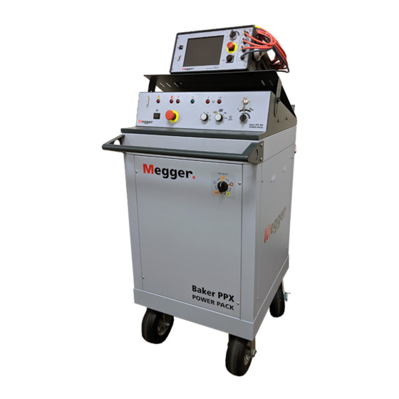
The button will remain locked in position until manually retracted by rotating the Equipment Stop button clockwise. Fig 1: Baker Power Pack showing Equipment Stop button. Item Description Equipment stop button Front panel Only Megger Baker Instruments supplied test leads designed for this instrument provide the full safety rating. www.megger.com... - Page 12 Baker Power Pack Introduction Baker Power Packs User Guide 71-061RC EN V2 www.megger.com...
-
Page 13: Baker Power Pack Introduction
I/O lines will be influenced and will cause problems with the analyzer’s operation. NOTICE: A power pack is purchased with, and calibrated to, the Baker DX or Baker AWA-IV tester host that it is shipped with. www.megger.com... -
Page 14: Power Pack Features Overview
Indicates when the high range has been selected. When this LED is blinking, the range switch has been moved to the low range and the setpoint is out of the surge voltage range. Baker Power Packs User Guide 71-061RC EN V2 www.megger.com... -
Page 15: Ppx40 Front Panel Controls
In the horizontal key position, zero-start override is enabled. Table 2: Ramp Rate Selector switch positions, voltage increments, and ramping times. Position Volts/second Time to Full Voltage (seconds) 2000 1000 www.megger.com... -
Page 16: Ppx30/30A Front Panel
PPX30/30A Front Panel The Baker PPX30 and PPX30A front panel is similar to the PPX40 except that it does not have a Surge Range switch. The Function Selector switch on the PPX30A includes a low-impedance test feature (signified by an armature icon) as shown in the example below. -
Page 17: Ppx30/30A Three-Phase Test Lead Selector Switch
PPX30/30A Three-Phase Test Lead Selector Switch The Baker PPX30 and PPX30A power packs are supplied with three-phase test leads. The Test Select switch is used to switch between the different test options HiPot or Surge, and to select the test leads (1, 2, 3) energized during Surge testing. -
Page 18: Ppx Tester Angle Adjustment
CAUTION: Ensure that both wing bolts and the safety strap are all securely tightened before using the tester in this manner. Keep all tools and body parts out of area below the adjustment plate to prevent damage or injury. Baker Power Packs User Guide 71-061RC EN V2 www.megger.com... -
Page 19: Ppx30/30A Configuration
Ground NOTICE: For Baker PPX30/30A power packs, you must place the power pack control panel Function Selector switch into the HiPot position to perform a HiPot test. Be sure to switch the power pack Test Select switch to the HiPot position. -
Page 20: Ppx30/30A Configuration For Dc Hipot Tests-Three-Phase Test Leads
PPX30/30A Configuration for DC HiPot Tests—Three-Phase Test Leads For the Baker PPX30/30A, you need only connect the power pack’s test leads to the motor leads once. The power pack’s Test Select switch internally configures the test leads for HiPot and Surge testing. -
Page 21: Ppx30/30A Configuration For Surge Tests-Three-Phase Test Leads
3. Set the Test Select switch to LEADS GROUND (ground icon). 4. Connect the power pack test leads to the motor leads as described in the table below. Table 6: Baker PPX30/30A device under test connections for Surge and HiPot testing. Test Lead 1... -
Page 22: Ppx40 Configuration
2. Check that the open ground detect warning banner does not appear in the Baker DX Display Area, or that the open ground detection light on the Baker AWA is not illuminated. Baker Power Packs User Guide 71-061RC EN V2 www.megger.com... -
Page 23: Baker Ppx40 Manual Surge Range Switch
In this position, the voltage will be limited to 25kV. 25–40kV Surge > 25 kV In this position, voltage is allowed to increase above 25kV, but surge pulses will not be generated if the voltage is lowered below 25kV. www.megger.com... - Page 24 Baker Power Pack Setup Baker Power Packs User Guide 71-061RC EN V2 www.megger.com...
-
Page 25: Baker Power Pack Setup
3. Connect the 25-pin interconnect cable to the receptacles on the back of the power pack and the tester. 4. Connect the long AC power cord from the AC receptacle on the side of the power pack to a properly grounded AC source. www.megger.com... - Page 26 Fig 11: Attaching accessories to the power pack. Item Description Remote E-stop and safety lights connector Footswitch connector Baker Power Packs User Guide 71-061RC EN V2 www.megger.com...
-
Page 27: Baker Awa To Power Pack Setup
AC source. Fig 12: Connect power pack to AC source and 25-pin interconnect cable. Item Description 25-pin interconnect cable—AWA and PPX front panel connectors PPX AC outlet to AWA AC inlet receptacle PPX AC inlet to properly grounded AC source www.megger.com... - Page 28 Using Power Packs with Baker AWA Testers Baker Power Packs User Guide 71-061RC EN V2 www.megger.com...
-
Page 29: Using Power Packs With Baker Awa Testers
4 — Using Power Packs with Baker AWA Testers The Baker AWA-IV 6 kV and 12 kV analyzers can be used with the Baker PPX30 power packs to test high-voltage motors that are beyond the capabilities of the testers alone. Generally speaking, the Baker AWA-IV 12 kV analyzer can test motors up to 1000 HP, 4160 volts, 1800 RPM on its own. -
Page 30: Creating Test And Motor Ids, And Setting Up The Tests
5. Enter the new Test ID in the appropriate field. In this example, we use PP30_6600. 6. Use the Target Motor Voltage Class drop-down menu to select a voltage class. For this example, we would select a voltage class of 6600. 7. Click OK to continue. Baker Power Packs User Guide 71-061RC EN V2 www.megger.com... -
Page 31: Define Test Parameters For The Test Id
DC HiPot testing. CAUTION: If the windings are not allowed to completely discharge, a voltage can develop on the motor leads that can be high enough to present a shock hazard to personnel. www.megger.com... - Page 32 The Surge Test setup window is shown below. In this example, the Surge Voltage has been set to 14000V and the Enable PP (power pack) box has been checked to turn on the power pack for this test. Fig 16: Surge test setup—PPX30/30A. 3. Click on the Close button to return to the Main window, Tests tab.
-
Page 33: Create A New Motor Id
Fig 17: Creating a new Motor ID. 3. After entering nameplate information, click on the Save button. The Select Test ID dialog box appears so you can select the Test ID that was created for the new motor. Fig 18: Create New Test ID dialog. www.megger.com... -
Page 34: Running The Combined Baker Awa-Iv And Power Pack Tests
The analyzer’s test leads are checked to verify that they are open. ƒ The Function knob is checked to verify it is in the proper position for the HiPot test. ƒ Baker Power Packs User Guide 71-061RC EN V2 www.megger.com... - Page 35 Continue to hold down the Test (PTT) button (or footswitch) until instructed to release When the test timer counts down to zero, the analyzer will automatically stop the test, disable the power pack’s test leads, and discharge the windings. www.megger.com...
- Page 36 17. After the HiPot test successfully completes, release the power pack’s Test (PTT) button (or footswitch). 18. Test results are automatically saved. 19. Next, the analyzer will automatically start the Surge test. Baker Power Packs User Guide 71-061RC EN V2 www.megger.com...
- Page 37 21. To start the Surge test, click on the Lead 1 button in the Run Surge section of the Surge Test configuration window. If you attempt to start by using the power pack’s Test (PTT) button, you will see a message instructing you to use the Lead 1 button. Fig 24: Surge Test start message. www.megger.com...
- Page 38 The software will lead you through the process as noted. 27. When you have completed testing all three phases, click on the Close button to return to the Main window, Tests tab. 28. Test results should be automatically saved. Baker Power Packs User Guide 71-061RC EN V2 www.megger.com...
-
Page 39: Single-Phase Testing-Ppx30/30A Combined With Baker Awa Tester
NOTE: The parameters set in the Temperature/Resistance Test setup window affect only the Megohm and DA/PI tests because the AWA test leads are used for these tests when used in combination with a PPX30/30A tester. The power pack’s test leads are used, in turn, for DC HiPot and Surge testing, which are not controlled by the AWA’s setup windows. -
Page 40: Single-Coil Testing
3. Set the Ramp Rate switch to 3 or 4 to start. You can adjust the rate as desired when testing the first coil. 4. Turn the PPX30/30A Zero-start Override key switch to the horizontal position to enable zero-start override. - Page 41 6. After creating the Test ID and Motor ID, select the Motor ID then open the Tests tab. 7. Ensure that the proper Test ID appears in the Test ID field. Fig 29: Selecting single coil testing Motor ID and Test ID. 8. Click on the test configuration button (volts) in the Surge Test row. www.megger.com...
- Page 42 13. Connect the power pack’s test cables to the first coil to be tested as described in the table below. Table 13: Baker PPX30/30A device under test connections for single-coil Surge testing; first coil tested. Test Lead 1...
- Page 43 20. Connect the power pack’s test cables to the rest of the coils to be tested (in turn) as described in the table below. Table 14: Baker PPX30/30A device under test connections for single-coil Surge testing; all subsequent coils being tested.
- Page 44 20 for the new coil. 29. Repeat this process for each new coil until you have tested all coils. 30. Click on Close to leave the Surge Test window when you have completed your testing. Baker Power Packs User Guide 71-061RC EN V2 www.megger.com...
-
Page 45: Single-Coil Testing Using A Test Reference
1. Connect the power pack’s test cables to a known-good coil as described in the table below. Table 15: Baker PPX30/30A device under test connections for single-coil Surge testing; reference coil. Test Lead 1 Test Lead 2... - Page 46 Fig 35: Setting Surge parameters; preparing to acquire a test reference. 22. Set your test parameters as needed (Surge Voltage according to device needs, others similar to the example shown above). Baker Power Packs User Guide 71-061RC EN V2 www.megger.com...
- Page 47 Test (PTT) button (or footswitch). 34. The software will alert you to release the power pack’s Test (PTT) button (or footswitch) when your waveform and voltage level stabilize. 35. Click the Close button in the Surge Tests window. www.megger.com...
- Page 48 44. If you will run only Surge tests, connect the next coil to be tested to the power pack’s test cables as described in the table below. Table 16: Baker PPX30/30A device under test connections for single-coil Surge testing. Test Lead 1...
- Page 49 For additional information on single-coil testing and details on related features, refer to the Baker AWA-IV User Guide. 50. If you need to test another coil, connect it to the tester as described above and repeat the process starting from step 42. www.megger.com...
-
Page 50: Low-Impedance Armature Or Coil Testing Using The Baker Ppx30A
4. The power pack’s high-voltage test leads are not used for this procedure. Ensure that they are not connected to anything and lay them safely aside. The black braided leads with circular surge and sense connectors are used instead. Baker Power Packs User Guide 71-061RC EN V2 www.megger.com... -
Page 51: Armature Testing Fixture Attachment
Surge Adapter 81-ATF-004RC 4. If you will use the remote E-Stop, connect it to the indicated location on the back of the power pack. 5. Ensure that the host unit and power pack setup procedures have been completed as described earlier. www.megger.com... -
Page 52: Low-Impedance Armature Or Coil Test Procedures For Ppx30A
With the key in the vertical position, testing starts at zero volts and must be ramped up to the target voltage level. In the horizontal key position, zero-start override is enabled. Baker Power Packs User Guide 71-061RC EN V2 www.megger.com... -
Page 53: Setting Up An Armature Surge Test
4. Enter the current password for editing Test IDs in the dialog box when requested. 5. Click the far right button in the Surge Test row to open the Surge Test setup window. Fig 42: Tests tab; selecting Surge Test setup to access armature testing parameters. www.megger.com... - Page 54 6. In the Surge Test setup window, define the Surge Voltage needed for your device. For this example, we use 600 volts. 7. Check the Enable PP box and the box labeled Arm. Fig 43: Setting up Surge Test window for Armature testing using the power pack. Baker Power Packs User Guide 71-061RC EN V2 www.megger.com...
- Page 55 15. Uncheck the Edit Test ID box to turn off Test ID editing. NOTE: The armature surge test is a manual test that cannot be performed using the automatic features of the Baker AWA-IV. 16. At this point, you can begin testing your armature (or other low-impedance device). www.megger.com...
-
Page 56: Running The Manual Armature Surge Test Using The Baker Awa And Ppx30A
7. In the following example, the target waveform is acquired from bar 1, so the Set Ref button is pressed. Fig 45: Acquiring the reference waveform for armature (low-impedance coil) testing. Baker Power Packs User Guide 71-061RC EN V2 www.megger.com... - Page 57 Bar Control field, or use the up and down arrows to navigate to the bar number, and retest as needed. Retesting will overwrite the previous data for that bar. 16. The Total Bars Tested number gives you the number of the last bar tested. Add one to that number to resume testing where you left off. www.megger.com...
- Page 58 18. Because this is not an automatic test, you must click on the yellow Save Results button to save the test results to the database so it can be recalled for further viewing and to print reports. Fig 47: Main view Tests tab after testing; Save Results. Baker Power Packs User Guide 71-061RC EN V2 www.megger.com...
-
Page 59: Using Power Packs With Baker Dx Testers
High-voltage power pack leads. Surge run from Power Packs. Surge testing PPX40 leads require manual configuration in three-phase mode. for three-phase testing. Power Packs Surge testing in single-coil mode. High-voltage power pack leads. Leads 1 and 2 only for single-phase testing. www.megger.com... -
Page 60: Running The Combined Baker Dx And Power Pack Tests
3. To prepare to conduct Step Voltage or DC HiPot tests with the power pack, ensure that the DX host leads are disconnected and the power pack leads connected. 4. Touch the Configuration Options icon then the Power Pack icon. Your start screen should look similar to the example shown above. Baker Power Packs User Guide 71-061RC EN V2 www.megger.com... - Page 61 If a Step Voltage test is run, the increments for each step are based on a starting voltage of 3300 (level for running Megohm, IR, and DA/PI tests). Two more increments of 3300 volts each will be used for each step (6600 and 9900). The final step will increment 4100 volts (14000) and will be run as a DC HiPot test. www.megger.com...
- Page 62 11. Touch the MOhm/PI icon to start that series of DC Tests (continuing to hold down the Test (PTT) button or footswitch throughout and following the test series). Fig 50: DC Test submenu items; MOhm/PI test selected (yellow highlight) after ramping to IR test voltage level. Baker Power Packs User Guide 71-061RC EN V2 www.megger.com...
- Page 63 On the Baker PPX30/30A, set the Test Select switch to the LEADS GROUND position before disconnecting test leads. On the Baker PPX40, wait to disconnect test leads until you see the leads energized lights go out followed by the sound of a relay switching.
- Page 64 This can only be achieved when using the Baker PPX to conduct all tests. The Test (PTT) button or footswitch is held down during the entire test suite and results are saved once at the end of the process. Fig 52: Example DC HiPot test report screen. Baker Power Packs User Guide 71-061RC EN V2 www.megger.com...
-
Page 65: Surge Test Procedures When Using Power Packs
For the Baker PPX30/30A, you need only connect the power pack’s test leads to the motor leads once. The position of the Baker PPX30/30A’s Test Select switch tells the power pack how to handle the test leads for HiPot and Surge testing. - Page 66 PP EAR graph that could be misinterpreted as surge wave instability. 12. Adjust the Ramp Rate Selector switch as desired. Table 19: Ramp Rate Selector switch positions, voltage increments, and ramping times. Position Volts/second Time to Full Voltage (seconds) 2000 1000 Baker Power Packs User Guide 71-061RC EN V2 www.megger.com...
- Page 67 18. Save the test results in the Active Folder/Active Record. NOTICE: Running another test without saving results from the previous test will overwrite the last test in memory. Shutting down the power pack prior to saving will also cause the loss of all unsaved data. www.megger.com...
- Page 68 WARNING: To prevent injury or death from electrical shock, always allow sufficient time for the test winding to completely discharge before disconnecting the test leads. On the Baker PPX30/30A, set the Test Select switch to the LEADS GROUND position before disconnecting test leads.
-
Page 69: Low-Impedance Armature Or Coil Testing Using The Baker Ppx30A
In the horizontal key position, zero-start override is enabled. When the zero-start override feature is enabled, target test voltage levels will be instantly applied to the test leads when a test begins. www.megger.com... - Page 70 9. Select a starting point armature bar to use as a reference. Typically, this will be bar 1, so the probe or fixture contacts will be placed on bars 1 and 2. Baker Power Packs User Guide 71-061RC EN V2 www.megger.com...
- Page 71 Fig 59: Armature bar test; acquiring the test reference. 13. From this point, the process is essentially the same as the standard process for Surge testing single coils. Refer to the “Surge Testing Procedure for Single-Coil Mode” found in the Baker DX User Guide for details. www.megger.com...
- Page 72 Record. It will save as Arm Bar data and it will appear on the results as such. Running the test continues adding armature coils up to 400, after which you must create a new record for an armature with more commutator bars. Baker Power Packs User Guide 71-061RC EN V2 www.megger.com...
- Page 73 Fig 62: Armature test report screen; simple example. In the simple example above, the EAR percentage for armature coil 12 is higher than most, but still within tolerance; however, armature coils 18 and 19 are out of limits. www.megger.com...
- Page 74 Baker Power Packs User Guide 71-061RC EN V2 www.megger.com...
-
Page 75: Appendix A - Maintenance
Leads are silicone insulated and work well in all weather conditions. Always keep the leads in a suitable lead bag when in storage or transportation. Regular inspection of leads is recommended to make sure that they are not damaged in any way. Damaged leads could affect resistance readings and are a safety hazard. www.megger.com... -
Page 76: Power Pack Lifting And Shipping
“PP” model power packs using this process. Always remove and safely store the tester before lifting the power pack. Do not attempt to lift the power pack with the tester sitting on top. Baker Power Packs User Guide 71-061RC EN V2 www.megger.com... -
Page 77: Appendix B - Troubleshooting
3. Current instructions for the return process are also provided via the above link. 4. Equipment returned to Megger Baker Instruments must be packaged in such a manner that it will reach the factory undamaged from transit. 5. For non-warranty repairs, Megger Baker Instruments service will provide a cost estimate for your approval prior to your shipping. - Page 78 Baker Power Packs User Guide 71-061RC EN V2 www.megger.com...
-
Page 79: Appendix C - Recommended Test Voltages
Recommended DC HiPot and Surge Test Voltages Megger Baker Instruments has a recommended standard (see table) for test voltages for DC tests and Surge tests conducted on a motor, generator, or transformer. That standard is twice the AC line voltage plus 1,000 volts. - Page 80 14,200 9,230 4,160 3,397 21,640 14,066 6,900 5,634 32,600 21,190 13,800 11,268 60,200 39,130 Table 25: Megger Baker Instruments recommended voltages. V Line Per Unit In Service, 2E + 1,000 1,960 2,150 2,200 2,300 1,878 5,600 4,160 3,397 9,320 6,900...
-
Page 81: Appendix D - Specifications
Appendix D — Specifications Electrical Specifications Specfication—Surge Test Baker PPX30 Baker PPX40 Baker PPX30A Maximum output voltage 30,000V 40,000V 30,000V Maximum output current with 1400A 2600A 1400A leads shorted together Maximum impulse energy 120J Accuracy Specfication—DC HiPot Test Baker PPX30... - Page 82 Baker Power Packs User Guide 71-061RC EN V2 www.megger.com...
-
Page 83: Appendix E - Accessories And Equipment
RLC adapter (for resistance testing) 81-ATF-002RC Surge and Sense Cable adapter (connects between PPX30A Surge and Sense connectors on 81-ATF-004RC rear of power pack, and ATF 5000 cable Surge and Sense connectors) ATF 5000 Armature Test Fixture (included with PPX30A) 84-ATF-001RC www.megger.com... - Page 84 Local Sales Office Megger USA - Fort Collins 4812 McMurry Ave., Suite 100 Fort Collins Colorado, 80525 1-970-282-1200 or 1-800-752-8272 1-282-1010 baker.sales@megger.com Manufacturing Sites Megger Limited Megger GmbH Megger USA - Valley Forge Archcliffe Road Obere Zeil 2 61440 Valley Forge Corporate Center...
Need help?
Do you have a question about the PPX30 and is the answer not in the manual?
Questions and answers