Table of Contents
Advertisement
Quick Links
MixSwitch
OWNER'S MANUAL
NORTH AMERICA (U.S., Canada, Mexico)
Contact Distribution Ltd.
38 Thornmount Drive, Unit #1
Scarborough, On M1B 5P2
Canada
Tel: 416-287-1144
Fax: 416-287-1204
E-mail: info@contactdistribution.com
service@contactdistribution.com
EUROPE AND UK
Pro Audio-Technik
Technologiezentrum Herzbachtal
Zum Wartturm 15
D-63571 Gelnhausen
Germany
Tel: +49 (0) 6051 - 914029
Fax: +49 (0) 6051 - 914059
E-mail: info@proaudio-technik.de
info@apb-dynasonics.com
Advertisement
Table of Contents

Summary of Contents for APB-DynaSonics MixSwitch
- Page 1 MixSwitch OWNER’S MANUAL NORTH AMERICA (U.S., Canada, Mexico) EUROPE AND UK Pro Audio-Technik Contact Distribution Ltd. Technologiezentrum Herzbachtal 38 Thornmount Drive, Unit #1 Zum Wartturm 15 Scarborough, On M1B 5P2 Canada D-63571 Gelnhausen Germany Tel: 416-287-1144 Tel: +49 (0) 6051 - 914029...
- Page 2 • This unit contains no user serviceable parts. All servicing must be performed by a qualified service engineer or through APB-DynaSonics or its qualified dealer. • Operate in accordance with U.S. Governments’ Occupational and Health Administration (OSHA) requirements, specifications, suggestions and regulations or those of any other local governing requirements where the equipment is to be used or serviced.
- Page 3 YOUR MIXSWITCH CONSOLE SWITCHING DEVICE Welcome to the APB-DynaSonics family. Please take a moment to review this manual. It will ensure a better understanding of the operation of this mixer and may open up new possibilities into how you use this product.
-
Page 4: Table Of Contents
INDEX Overview FRONT PANELS......................................6 REAR PANELS........................................7 BLOCK DIAGRAM......................................8-9 FUNCTIONAL DESCRIPTION ................................... 10-11 A & B Main Inputs LEVEL MONITORING & LISTENING............................... 12 REAR PANEL CONNECTORS ..................................13 Auxiliary Sources ANNOUNCE MIC ......................................14-15 STEREO PROGRAM INPUT ..................................16-17 STEREO LINE INPUT..................................... - Page 5 Front Panel Overview Master Front Panel Expander Front Panel...
-
Page 6: Rear Panels
Rear Panel Overview Master Rear Panel Expander Rear Panel... -
Page 7: Front Panels
+4dBu Line In R +4dBu Str Line Limiter ––––– Limit Rear Connectors (L-R) Threshold Assign (Adj) Stereo Opto Limiter Output MixSwitch - Aux Inputs Listen 1/8” 1/4” Mini-Jack Jack Local Listen Expander Listen Headphone Mix Amps Level Receiver Headphone Jacks... - Page 8 Select A Select B Relay Controls Listen Logic Control Audio & DC Green Green Yellow Switch Power Sequencer On• •Off Mute A&B On• •Off D-Sub 9 Control Logic Hold to Toggle To MixSwitch Expanders APB-DynaSonics MixSwitch Block Diagram Rev 0.95 11-Sep-10...
-
Page 9: Functional Description
The gain-staging of the MixSwitch provides the headroom needed for this function. Although the main function of the MixSwitch is basically simple, we had to insure that it was as transparent to the audio signals as possible. To this end, we’ve used the latest and greatest interface chips available from THAT Corp to make connecting to the outside world as trouble-free as possible. - Page 10 A & B Additive Operation: When the A & B Mode switch is set to “Sum” (white button down, Red LED illuminated), the MixSwitch will allow both sets of Inputs to be routed to the Outputs. The A & B buttons do not interact while in this Mode.
-
Page 11: Level Monitoring & Listening
Input-1 is heard on the Left and Input-2 is heard on the Right. This allows you to listen to a stereo source in stereo if it’s being fed to the MixSwitch on Input pair A1-A2 or Input pair B1-B2. -
Page 12: Rear Panel Connectors
NOTE: When unpowered, the MixSwitch will hard-bypass the A-Inputs to their respective Outputs via internal relays. When bypassed, no internal circuitry is connected to the XLR jacks except for these relays (i.e. True-bypass mode). When the MixSwitch is hard-bypassed, the transformers (if installed) are also bypassed and not in the audio path. -
Page 13: Announce Mic
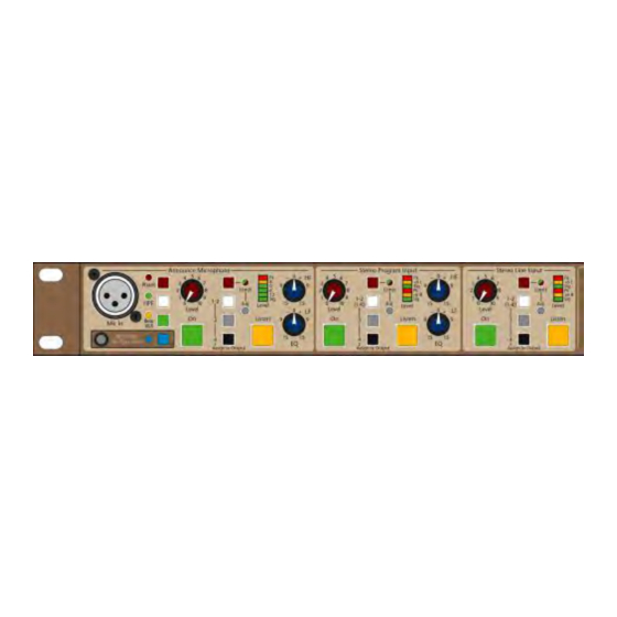
MixSwitch - Auxiliary Sources In addition to the main A & B Inputs, the MixSwitch has 3 supplementary audio inputs. 1) Announce Mic 2) Stereo Program In 3) Stereo Line In These 3 inputs are called the Auxiliary Sources. These signals can be routed to any of the 4 outputs total independent of the Main A &... - Page 14 When On, the Announce Mic signal will feed any assigned Outputs. Note: The On/Off state this soft-latching switch will normally be remembered and restored if the MixSwitch temporarily loses power. An internal jumper allows the restore function to set only the “A” input On, Clear ALL soft-latching switches, or restore the state of ALL soft-latching switches.
-
Page 15: Stereo Program Input
MixSwitch - Auxiliary Sources Stereo Program Input Front Panel Controls and Input This section accepts a Line-level signal from Rear-panel TRS and RCA jacks; both input sources are active and will be combined into a single stereo source if both sets of jacks are used. This Input can be used to provide music before, during or after a show. - Page 16 When On, the Stereo Program signal will feed any assigned Outputs. Note: The On/Off state this soft-latching switch will normally be remembered and restored if the MixSwitch temporarily loses power. An internal jumper allows the restore function to set only the “A” input On, Clear ALL soft-latching switches, or restore the state of ALL soft-latching switches.
-
Page 17: Stereo Line Input
MixSwitch - Auxiliary Sources Stereo Line Input Front Panel Controls This section is similar to the Stereo Program Input, but lacks the EQ. Input source is a Line-level signal from Rear-panel XLR jacks; these balanced inputs are fitted with InGenius balanced Receivers. This Input can be used to feed an additional console into the system or any additional line-level signals needed for the show. - Page 18 When On, the Stereo Line signal will feed any assigned Outputs. Note: The On/Off state this soft-latching switch will normally be remembered and restored if the MixSwitch temporarily loses power. An internal jumper allows the restore function to set only the “A” input On, Clear ALL soft-latching switches, or restore the state of ALL soft-latching switches.
-
Page 19: Auxiliary Sources - Rear Connectors
MixSwitch - Auxiliary Sources - Rear Connectors Aux Inputs: The input jacks for all 3 Aux Sources are located on the rear panel of the MixSwitch. -
Page 20: Remote Control Of Master
The MixSwitch Master is fitted with 2 DSub connectors for Remote operation and Expander-control. The DSub-15 allows the MixSwitch Master to be remotely operated; all of the 6 soft-latching switches can be remotely toggled. Tally lines allow the operator to monitor the status of each switch. -
Page 21: Specifications
TECHNICAL SPECIFICATIONS General Specifications Frequency Response (A or B input to Output) +0/-0.1dB 5Hz to 50kHz (ref to 1kHz) THD + Noise (A or B Input to Output) <0.005% @ +15dBu output 20Hz to 20kHz Phase Response (A or B Input to Output) +2/-2 degrees 20Hz to 20kHz (ref to 1kHz) Noise Output Noise- No Inputs Selected...
Need help?
Do you have a question about the MixSwitch and is the answer not in the manual?
Questions and answers