Table of Contents
Advertisement
Quick Links
Advertisement
Table of Contents

Subscribe to Our Youtube Channel
Related Manuals for ESCO Technologies ETS-Lindgren HI-6122

Summary of Contents for ESCO Technologies ETS-Lindgren HI-6122
- Page 1 HI-6122, HI-6105, HI-6153 HI-6023, HI-6006, HI-6053 EMC Field Probes User Manual...
- Page 2 ETS-Lindgren Inc. reserves the right to make changes to any products herein to improve functioning or design. Although the information in this document has been carefully reviewed and is believed to be reliable, ETS-Lindgren does not assume any liability arising out of the application or use of any product or circuit described herein;...
-
Page 3: Table Of Contents
Table of Contents Notes, Cautions, and Warnings ..........viii Laser Safety Considerations ..........viii Recycling & Disposal Information .......... ix ETS-Lindgren Product Information Bulletin ......ix 1.0 Introduction ................ 11 Standard Configuration ................11 Readout Options ..................12 HI-6100 Field Monitor (For Laser & Battery Probes) ......12 HI-6113 Laser Data Interface (For Laser Probes)...... - Page 4 Upgrade Policies ..................32 Service Procedures .................. 33 Contacting ETS-Lindgren ..............33 Sending a Component for Service............. 33 Calibration Services and Annual Calibration........33 4.0 Specifications ..............35 Laser-Powered Probe Specifications ............35 HI-6122 Specifications ..............35 HI-6105 Specifications ..............36 HI-6153 Specifications ..............
- Page 5 HI-6153 Typical Isotropic Response ..........60 8.0 Typical Data: Battery-Operated Probes ......63 HI-6023 Typical Data ................63 HI-6023 Typical Frequency Response with Limits ......63 HI-6023 Typical Isotropic Response ..........64 HI-6006 Typical Data ................65 HI-6006 Typical Frequency Response with Limits ......65 HI-6006 Typical Isotropic Response ..........
- Page 6 Appendix D: Operating Protocols .......... 89 Communication Protocol ................89 HI-61XX Series LaserPro Field Probes ..........89 HI-60XX Series Battery-Operated Field Probes ........ 89 Information Transfer Protocol ..............90 Command Structure ................90 Probe Commands ..................91 HI-61XX Series LaserPro Field Probes ..........91 HI-60XX Series Field Probes ............
- Page 7 ETS_InitiateReadBattery() ...............119 ETS_InitiateReadField() ..............120 ETS_InitiateReadTemperature() ............121 ETS_IsOperationComplete() ............122 ETS_Model()..................123 ETS_ProbeName() ................124 ETS_ReadBatterySynchronous() .............125 ETS_ReadTemperatureSynchronous() ..........126 ETS_SerialNumber() ................127 ETS_SetRange() ................128 ETS_SetUnits() ................129 ETS_TemperatureC() ..............130 ETS_LaserCurrent() .................131 ETS_Version() .................132 ETS_SupplyVoltage() ..............133 ETS_LaserTemperature() ..............134 ETS_ZeroProbe()................135 Status Codes ...................136 Appendix F: EC Declaration of Conformity ......139 Applicable Requirements .................139 ets-lindgren.com...
-
Page 8: Notes, Cautions, And Warnings
Notes, Cautions, and Warnings Note: Denotes helpful information intended to provide tips for better use of the product. Caution: Denotes a hazard. Failure to follow instructions could result in minor personal injury and/or property damage. Included text gives proper procedures. Warning: Denotes a hazard. -
Page 9: Recycling & Disposal Information
Recycling & Disposal Information Waste Electrical and Electronic Equipment (WEEE) Directive: (European Union) At end of useful life, this product should be deposited at an appropriate waste disposal facility for recycling and disposal. Do not dispose of with household waste. Recyclable Products: This product includes rechargeable batteries. - Page 10 This page intentionally left blank. ets-lindgren.com...
-
Page 11: 1.0 Introduction
1.0 Introduction The ETS-Lindgren EMC Field Probes embody the latest innovations in isotropic sensor design and low-noise, miniaturized electronics. Each probe is a fully intelligent sensor enabling fast and accurate EMF measurements with industry-leading performance specifications. Optical coupling to a variety of readout options makes these probes ideally suited for a wide range of field monitoring applications. -
Page 12: Readout Options
Readout Options Note: For more information on using these readout options with ETS-Lindgren probes, see Typical Configurations on page 17. HI-6100 F & B IELD ONITOR ASER ATTERY ROBES The HI-6100 Field Monitor accepts inputs from up to any four probes, and analyzes and displays information on a user-configurable LCD. -
Page 13: Hi-4413P Fiber Optic Modem (For Battery Probes)
HI-4413P F IBER PTIC ODEM ATTERY ROBES The battery-powered probes use the HI-4413P Fiber Optic Modem to communicate with ProbeView II™ software through a serial port on the computer. HI-4413P Fiber Optic Modem HI-4413USB F USB C IBER PTIC TO ONVERTER ATTERY ROBES... -
Page 14: Additional Options
Additional Options H-491009 T RIPOD The H-491009 Dielectric Tripod is the preferred method for mounting field probes for making unperturbed field measurements. It includes a 1/4–20 UNC threaded stud for mounting any ETS-Lindgren probe with a tripod mount. It is designed with an adjustable center post and a rotating mount. -
Page 15: Probe Stand
ROBE TAND The ETS-Lindgren Probe Stand may also be used in testing configurations. The probe stand supports up to two probes. ets-lindgren.com Introduction... -
Page 16: About Probe Operation
About Probe Operation Note: For information on reducing measurement uncertainties and selecting the best field probe for your application, see Practical Considerations for Radiated Immunities Measurement using ETS-Lindgren EMC Probes located in the white papers section on the ETS-Lindgren website: www.ets-lindgren.com. Note: For complete information on setting up and operating the field monitor, software, and other devices available for the laser and battery-operated field probes, please see the documentation... -
Page 17: 2.0 Typical Configurations
2.0 Typical Configurations A variety of configurations are available with the field monitors, probes, and other devices. Following are typical examples of how the components can be assembled to accommodate most testing environments. HI-6100 Field Monitor Configuration—see page 17 ... -
Page 18: Hi-6113 Laser Data Interface Configuration
HI-6113 Laser Data Interface Configuration The following diagram illustrates the ETS-Lindgren probes that may be used with the HI-6113 Laser Data Interface (LDI). In the diagram, the USB in HI-6153USB, for example, refers to USB Kit. As a kit, the probe includes all components required to operate the probe with the HI-6113. -
Page 19: Hi-4413P / Hi-4413Usb Configuration
HI-4413P / HI-4413USB Configuration The following diagram illustrates the ETS-Lindgren probes that may be used with the HI-4413P Fiber Optic Modem or the HI-4413USB Fiber Optic to USB Converter. ets-lindgren.com Typical Configurations... - Page 20 This page intentionally left blank. Typical Configurations ets-lindgren.com...
-
Page 21: 3.0 Maintenance
3.0 Maintenance CAUTION: Before performing any maintenance, follow the safety information in the ETS-Lindgren Product Information Bulletin included with your shipment. WARNING: Maintenance of probes is limited to external components such as cables, connectors, and probe shields (select models only; see page 21). For information on fiber optic cable and connector maintenance, see Laser Probes and Maintenance of Fiber Optics on page 25. - Page 22 If the probe shields need to be replaced, you may order them from ETS-Lindgren. Follow these steps to replace the probe shields: Remove the nylon screws from the probe shield. Lift the shield straight up and away from the housing. Note: Lift the shield high enough to clear the internal antenna assembly, or you may damage the assembly.
-
Page 23: Battery Replacement
Battery Replacement HI-6023 & HI-6006 B ATTERY EPLACEMENT Note: To order replacement screws for the HI-6023/HI-6006 battery hatch, see page 31. Note: The HI-6006 probe is shown in the following steps; the steps are identical for the HI-6023. Rotate the two hatch screws and remove. - Page 24 Remove the hatch. Remove the spent battery. Note: Notice the location of the + (positive) and – (negative) marks on the battery and inside the probe. You will use these marks in step 4 to install the new battery. Maintenance ets-lindgren.com...
- Page 25 Insert the new battery, making sure to align the + (positive) and – (negative) marks on the battery with the marks on the probe. Replace the hatch and the two screws. ets-lindgren.com Maintenance...
-
Page 26: Hi-6053 Battery Replacement
HI-6053 B ATTERY EPLACEMENT During the annual calibration of your HI-6053 at the ETS-Lindgren factory, the batteries are tested to verify continued operability. If required, the batteries are replaced at that time. It is rare that you should need to replace the batteries between calibration checks, but in that event, follow these steps. - Page 27 A single connector attaches the two boards together. Withdraw the two boards from the housing at the same time. The boards should easily slide out of the tracks. Detach the two boards by carefully separating them at the connector, avoiding damage to the pins. Replace the four AAA rechargeable NiMH batteries, orienting the +/- ends as indicated.
-
Page 28: Laser Probes And Maintenance Of Fiber Optics
Laser Probes and Maintenance of Fiber Optics Fiber optic connectors and cables can be damaged from airborne particles, humidity and moisture, oils from the human body, and debris from the connectors they plug into. Always handle connectors and cables with care, using the following guidelines. -
Page 29: Replacement And Optional Parts
Replacement and Optional Parts Note: ETS-Lindgren may substitute a similar part or new part number with the same functionality for another part/part number. Contact ETS-Lindgren for questions about part numbers and ordering parts. Following are the part numbers for ordering replacement or optional parts for the EMC Probes. -
Page 30: Probe Shields
ROBE HIELDS Note: The probe shield replacement kit includes: Three probe shields (cones) One each X, Y, and Z axis label Six screws For Probe Model Part Number HI-6122, HI-6023 112955 HI-6105 H-491237 HI-6006 H-651016 ABLES ONNECTORS AINTENANCE LEANING For Probe Model... -
Page 31: Battery Charger, Battery, Battery Hatch Replacement Screws
For Probe Model Part Description Part Number Cable, Fiber Optic, H-491106-xx Glass (xx=length in meters) HI-6023, HI-6006, HI-6053 Connector Set, H-231205000 two required (Bulkhead Feedthrough) ATTERY HARGER ATTERY ATTERY ATCH EPLACEMENT CREWS Battery Charger For Probe Model Part Number HI-6023, HI-6006 H-491198-48 HI-6053 H-491198-01... -
Page 32: Carrying Cases
ARRYING ASES For Probe Model Part Number HI-6122, HI-6105 H-491260 H-6023, HI-6006 HI-6153, HI-6053 H-491291 RIPOD ROBE TAND For Probe Model Part Description Part Number Tripod, Dielectric H-491009 Probe Stand H-491269 All Probe Models Probe Carrier for H-491276 H-491269 Probe Stand Upgrade Policies Periodically, probes are upgraded to enhance functionality. -
Page 33: Service Procedures
Service Procedures ETS-L ONTACTING INDGREN Note: Please see www.ets-lindgren.com for a list of ETS-Lindgren offices, including phone and email contact information. ENDING A OMPONENT FOR ERVICE For the steps to return a system or system component to ETS-Lindgren for service, see the Product Information Bulletin included with your shipment. ALIBRATION ERVICES AND NNUAL... - Page 34 This page intentionally left blank. Maintenance ets-lindgren.com...
-
Page 35: 4.0 Specifications
4.0 Specifications Note: For battery charger specifications, see Appendix B on page 73 or Appendix C on page 81, depending on your battery charger model. Laser-Powered Probe Specifications HI-6122 S PECIFICATIONS 2.0 – 800 Volts per meter (V/m) Dynamic Range: Ranges: Single Typical Frequency Response:... -
Page 36: Hi-6105 Specifications
Environmental ° ° Operating Temperature: C to 40 ° ° F to 104 Humidity: 5% to 95% relative humidity, non-condensing Dimensions Housing: 32 mm x 32 mm x 32 mm 1.26 in x 1.26 in x 1.26 in Probe Shields: 36 mm (1.42 in) Weight: 80 g (2.82 oz) - Page 37 Physical Interface: Duplex optical fiber (62.5 micron multimode) FC connectors for laser cable, integral 1-m optical cable ST connector for transmitter cable, integral 1-m optical cable Probe Mount: 1/4–20 UNC (internal thread) Dimensions Housing: 32 mm x 32 mm x 32 mm 1.26 in x 1.26 in x 1.26 in Probe Shields: 43 mm (1.69 in)
-
Page 38: Hi-6153 Specifications
HI-6153 S PECIFICATIONS Dynamic Range: 2.0–800 Volts per meter (V/m) Ranges: Single Typical Frequency Response: 10 MHz–40 GHz 10 MHz–100 MHz: +3 dB, -4 dB 100 MHz–1 GHz: +3 dB, -0.5 dB 1 GHz–18 GHz: +4 dB, -2 dB ... -
Page 39: Battery-Operated Probe Specifications
Environmental ° ° Operating Temperature: C to 40 ° ° F to 104 Humidity: 5% to 95% relative humidity, non-condensing Dimensions Probe Length: 438 mm (17.24 in) (includes electronics housing) Probe Diameter: 57 mm (2.24 in) Weight: 0.36 kg (12.64 oz) Battery-Operated Probe Specifications HI-6023 S PECIFICATIONS... - Page 40 Fiber Optic Cable Connector: Standard FSMA Probe Mount: 1/4–20 UNC tapped hole (internal thread) Battery: Rechargeable Nickel-Metal Hydride (NiMH) Battery Life: Up to 8 hours Battery Charger: 100–240 VAC universal input 3-hour charge from full depletion Environmental ° °...
-
Page 41: Hi-6006 Specifications
HI-6006 S PECIFICATIONS Dynamic Range: 0.5–800 Volts per meter (V/m) Single Range (64 dB) Typical Frequency Response: 100 kHz–6 GHz 500 kHz–2 GHz: +1 dB, -2.5 dB 2 GHz–5.5 GHz: +3.5 dB, -4 dB 5.5 GHz–6 GHz: +2 dB, -6 dB Typical Frequency Response 100 kHz–6 GHz: ±0.9 dB with Correction:... -
Page 42: Hi-6053 Specifications
Dimensions Housing: 32 mm x 32 mm x 32 mm 1.26 in x 1.26 in x 1.26 in Probe Shields: 43 mm (1.69 in) Weight: 0.08 kg (2.6 oz) Environmental ° ° Operating Temperature: C to 40 ° ° F to 104 Humidity: 5% to 95% relative humidity, non-condensing... - Page 43 Overload Withstand: 1,500 V/m Fiber Optic Cable Connector: Standard FSMA Probe Mount: 1/4–20 UNC tapped hole (internal thread) Battery: Four AAA batteries, rechargeable Nickel-Metal Hydride (NiMH) Battery Charger: 100–240 VAC Approximately three hours Battery Life: > 30 hours continuous (at full charge) Environmental °...
- Page 44 This page intentionally left blank. Specifications ets-lindgren.com...
-
Page 45: 5.0 Laser-Powered Field Probes
5.0 Laser-Powered Field Probes The HI-61XX Series LaserPro™ Field Probe is a laser-powered probe, an excellent tool for electric field mapping, industrial monitoring, and EMC field measurements. The HI-61XX Series probes contain a photo-voltaic converter that provides power to the probe circuitry when sufficient light power is received by the converter. The light power is generated by a laser in the HI-6113 Laser Data Interface, and is transmitted to the converter through an optical fiber in the duplex fiber optic cable. -
Page 46: Hi-6122 Electric Field Probe
HI-6122 Electric Field Probe The ETS-Lindgren HI-6122 Field Probe provides broadband frequency coverage and wide dynamic range that satisfies the demands of most test requirements. The frequency response of the HI-6122 is 10 kHz to 1 GHz, and the dynamic range is 2 to 800 Volts per meter (V/m). -
Page 47: Hi-6153 Electric Field Probe
HI-6153 Electric Field Probe The ETS-Lindgren HI-6153 Field Probe provides broadband frequency coverage and wide dynamic range that satisfies the demands of most test requirements. The frequency response of the HI-6153 is 10 MHz to 40 GHz, and the dynamic range is 2 to 800 Volts per meter (V/m). - Page 48 The HI-6153 is a true 3-axis probe. When requested, X, Y, Z, and total field data can be reported. Laser-Powered Field Probes ets-lindgren.com...
-
Page 49: 6.0 Battery-Operated Field Probes
6.0 Battery-Operated Field Probes Note: Before using your battery-operated probe, read the following: HI-6023 and HI-6006 Field Probe: Appendix C: Series H-491198-48 Battery Charger on page 81. HI-6053 Field Probe: Appendix B: Series H-491198-01 Battery Charger on page 73. Note: To calibrate the probe prior to shipment, ETS-Lindgren also charges the internal battery at the factory. -
Page 50: Hi-6023 Field Probe
HI-6023 Field Probe The ETS-Lindgren HI-6023 Field Probe provides broadband frequency coverage and wide dynamic range that satisfies the demands of most test requirements. The frequency response of the HI-6023 is 10 kHz to 1 GHz, and the dynamic range is 2 to 800 Volts per meter (V/m). -
Page 51: Hi-6006 Field Probe
HI-6006 Field Probe The ETS-Lindgren HI-6006 Field Probe is a fully intelligent sensor enabling fast and accurate EMF measurements with industry-leading performance specifications. Optical coupling to a variety of readout options makes this probe ideally suited for a wide range of field monitoring applications. -
Page 52: Hi-6053 Field Probe
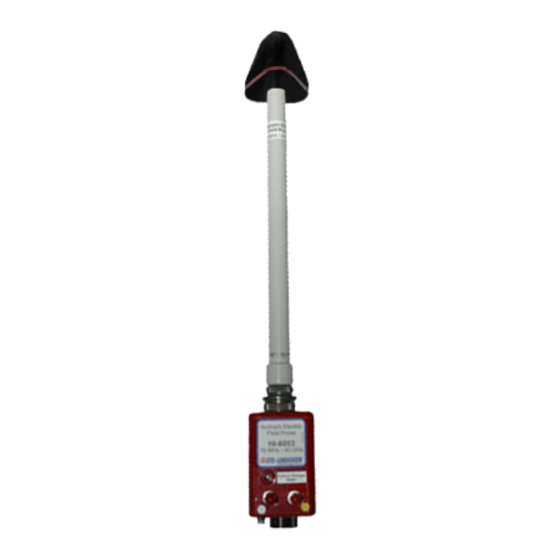
HI-6053 Field Probe The ETS-Lindgren HI-6053 Field Probe provides broadband frequency coverage and wide dynamic range that satisfies the demands of most test requirements. The frequency response of the HI-6053 is 10 MHz to 40 GHz, and the dynamic range is 2 to 800 Volts per meter (V/m). The HI-6053 assembly consists of a pyramidal casing containing the sensor, which is mounted on one... -
Page 53: Hi-6053 Power Switch
The HI-6053 is a true 3-axis probe. When requested, X, Y, Z, and total field data can be reported. HI-6053 P OWER WITCH The power button that activates and deactivates the HI-6053 is located on the bottom of the electronic housing. A green indicator light in the power button flashes when the probe is on. -
Page 54: Hi-6053 Controls
On—To turn the HI-6053 on, push in the power button, and then release. The power button flashes a green indicator light when the probe is on, and four AAA Nickel-Metal Hydride (NiMH) batteries supply power. Off—To turn the HI-6053 off, push in the power button, and then release. -
Page 55: 7.0 Typical Data: Laser-Powered Probes
7.0 Typical Data: Laser-Powered Probes HI-6122 Typical Data HI-6122 T YPICAL REQUENCY ESPONSE Note: TEM Cell and GTEM! – Field Level 20 V/m. ets-lindgren.com Typical Data: Laser-Powered Probes... -
Page 56: Hi-6122 Typical Isotropic Response
HI-6122 T YPICAL SOTROPIC ESPONSE Note: Isotropic response measured in a 20 V/m field at 400 MHz. Typical Data: Laser-Powered Probes ets-lindgren.com... -
Page 57: Hi-6105 Typical Data
HI-6105 Typical Data HI-6105 T YPICAL REQUENCY ESPONSE Note: Anechoic Room and TEM Cell – Field Level 20 V/m. ets-lindgren.com Typical Data: Laser-Powered Probes... -
Page 58: Hi-6105 Typical Isotropic Response
HI-6105 T YPICAL SOTROPIC ESPONSE Note: Actual data taken at 400 MHz, field level 20 V/m, maximum variation 0.54 dB. Typical Data: Laser-Powered Probes ets-lindgren.com... -
Page 59: Hi-6153 Typical Data
HI-6153 Typical Data HI-6153 T YPICAL REQUENCY ESPONSE Note: Field Level 20 V/m. ets-lindgren.com Typical Data: Laser-Powered Probes... -
Page 60: Hi-6153 Typical Isotropic Response
HI-6153 T YPICAL SOTROPIC ESPONSE Typical Isotropic Response in dB at 1 GHz Typical Data: Laser-Powered Probes ets-lindgren.com... - Page 61 Typical Isotropic Response in dB at 10 GHz ets-lindgren.com Typical Data: Laser-Powered Probes...
- Page 62 Typical Isotropic Response in dB at 18 GHz Typical Data: Laser-Powered Probes ets-lindgren.com...
-
Page 63: 8.0 Typical Data: Battery-Operated Probes
8.0 Typical Data: Battery-Operated Probes HI-6023 Typical Data HI-6023 T YPICAL REQUENCY ESPONSE WITH IMITS Note: TEM Cell and GTEM! – Field Level 20 V/m. ets-lindgren.com Typical Data: Battery-Operated Probes... -
Page 64: Hi-6023 Typical Isotropic Response
HI-6023 T YPICAL SOTROPIC ESPONSE Note: Isotropic response measured in a 20 V/m field at 400 MHz. Typical Data: Battery-Operated Probes ets-lindgren.com... -
Page 65: Hi-6006 Typical Data
HI-6006 Typical Data HI-6006 T YPICAL REQUENCY ESPONSE WITH IMITS Note: Anechoic Room and TEM Cell – Field Level 20 V/m. ets-lindgren.com Typical Data: Battery-Operated Probes... -
Page 66: Hi-6006 Typical Isotropic Response
HI-6006 T YPICAL SOTROPIC ESPONSE Note: Actual data taken at 400 MHz, field level 20 V/m, maximum variation 0.54 dB. Typical Data: Battery-Operated Probes ets-lindgren.com... -
Page 67: Hi-6053 Typical Data
HI-6053 Typical Data HI-6053 T YPICAL REQUENCY ESPONSE Note: Field Level 20 V/m. ets-lindgren.com Typical Data: Battery-Operated Probes... -
Page 68: Hi-6053 Typical Isotropic Response
HI-6053 T YPICAL SOTROPIC ESPONSE Typical Isotropic Response in dB at 1 GHz Typical Data: Battery-Operated Probes ets-lindgren.com... - Page 69 Typical Isotropic Response in dB at 10 GHz ets-lindgren.com Typical Data: Battery-Operated Probes...
- Page 70 Typical Isotropic Response in dB at 18 GHz Typical Data: Battery-Operated Probes ets-lindgren.com...
-
Page 71: Appendix A: Warranty
Appendix A: Warranty Note: See the Product Information Bulletin included with your shipment for the complete ETS-Lindgren warranty for your EMC Field Probe. Duration of Warranties All product warranties, except the warranty of title, and all remedies for warranty failures are limited to three years. Product Warranted Duration of Warranty Period HI-6122... - Page 72 This page intentionally left blank. Warranty ets-lindgren.com...
-
Page 73: Appendix B: Series H-491198-01 Battery Charger
Appendix B: Series H-491198-01 Battery Charger For NiMH Batteries Note: The HI-6053 Field Probe contains four AAA Nickel-Metal Hydride (NiMH) batteries, and uses the Series H-491198-01 Battery Charger. Safety Precautions Caution: Before operating the Series H-491198-01 Battery Charger, see Laser Safety Considerations on page viii. Introduction The H-491198-01 Nickel-Metal Hydride (NiMH) Battery Charger is... -
Page 74: Battery Life
Battery Life The NiMH batteries powering the battery-operated probe have high energy density for maximum operating time between charges, but also have a significant self-discharge characteristic. When the probe is stored for longer than a week or two, the batteries will discharge even though not in use. Leaving the batteries in a discharged condition for long periods of time may result in reduced battery life. -
Page 75: Charging The Batteries
Fully charged batteries (nominal output voltage of 4.8 VDC) provide up to 30 hours of operation. When the batteries have discharged to 4.4 VDC, the probe will operate, but the batteries need to be charged. When the voltage drops below 4.0 VDC, measurement accuracy may be compromised by continued operation. -
Page 76: Charging Indicators
HARGING NDICATORS The following LEDs are located on the front of the battery charger: POWER ON (green)—Indicates the battery charger is connected to the AC power source. NO BATTERY (amber)—Indicates the battery charger does not detect a battery. ... -
Page 77: Synchronizing The Battery Charge Indicator
Following the maximum time of 180 minutes, a pulse-trickle charge mode is used to compensate for the self-discharge of the batteries while idle in the charger. The fast charge current is low enough that there is not always enough heating of the battery cells to cause the voltage to drop. -
Page 78: Discharging A Battery
ISCHARGING A ATTERY To discharge the batteries: Make sure the probe is off or the batteries will not charge. Connect the battery charger to the electrical mains, and then plug the charger output into the battery charger connector on the probe. Press the DISCHARGE button on the battery charger. -
Page 79: Maintenance Recommendations
Output Open Circuit Voltage: 12 Vdc Fast Charge Pending Current: 2.0 mA Fast Charge Current: 220 mA Pulsed Trickle Charge Current: 2.0 mA Output Voltage (During Fast 4–8 Vdc Charge): Environmental ° ° Operating Temperature: C to 40 ° ° F to 104 Humidity: 5% to 95% relative humidity,... -
Page 80: Replacing The Fuse
EPLACING THE Caution: Disconnect the battery charger from power before replacing a fuse. If the battery charger fails to operate, check for a blown fuse inside the power entry module. A blown fuse must be replaced with the same value and type of fuse, or an unsafe condition may result. -
Page 81: Appendix C: Series H-491198-48 Battery Charger
Appendix C: Series H-491198-48 Battery Charger For NiMH Batteries Note: The HI-6023 and HI-6006 probes contain a Nickel-Metal Hydride (NiMH) battery, and use the Series H-491198-48 Battery Charger. Safety Precautions Caution: Before operating the Series H-491198-48 Battery Charger, see Laser Safety Considerations on page viii. Introduction The H-491198-48 Nickel-Metal Hydride (NiMH) Battery Charger is a dual power... -
Page 82: Battery Life
Battery Life The NiMH battery powering the battery-operated probe has high energy density for maximum operating time between charges, but also has a significant self- discharge characteristic. When the probe is stored for longer than a week or two, the battery will discharge even though not in use. Leaving the battery in a discharged condition for long periods of time may result in reduced battery life. -
Page 83: Charging A Battery
A fully charged battery (nominal output voltage of 4.8 VDC) provides up to 10 hours of operation. When the battery has discharged to 4.4 VDC, the probe will operate, but the battery will need to be charged. When the voltage drops below 4.0 VDC, measurement accuracy may be compromised by continued operation. -
Page 84: Charging Indicators
HARGING NDICATORS The following LEDs are located on the front of the battery charger: POWER ON (green)—Indicates the battery charger is connected to the AC power source. NO BATTERY (amber)—Indicates the battery charger does not detect a battery. ... -
Page 85: Synchronizing The Battery Charge Indicator
Following the maximum time of 180 minutes, a pulse-trickle charge mode is used to compensate for the self-discharge of the battery while idle in the charger. The batteries are small, and the fast charge current is low. The fast charge current is low enough that there is not always enough heating of the battery cells to cause the voltage to drop. -
Page 86: Discharging A Battery
ISCHARGING A ATTERY To discharge a battery: Make sure the power switch on the probe is set to the OFF position or the battery will not charge. Connect the battery charger to the electrical mains, and then connect the charger output to the charger jack on the probe. Press the DISCHARGE button on the battery charger. -
Page 87: Maintenance Recommendations
Output Open Circuit Voltage: 12 Vdc Fast Charge Pending Current: 2.0 mA Fast Charge Current: 25 mA Pulsed Trickle Charge Current: 2.0 mA Output Voltage (During Fast 4–8 Vdc Charge): Environmental ° ° Operating Temperature: C to 40 ° ° F to 104 Humidity: 5% to 95% relative humidity,... -
Page 88: Replacing The Fuse
EPLACING THE Caution: Disconnect the battery charger from power before replacing a fuse. If the battery charger fails to operate, check for a blown fuse inside the power entry module. A blown fuse must be replaced with the same value and type of fuse, or an unsafe condition may result. -
Page 89: Appendix D: Operating Protocols
Appendix D: Operating Protocols Note: The information in this section is subject to change, and is included for reference only. ETS-Lindgren recommends that you use the commands and information provided in ETSProbe DLL User Guide on page 99. The following information assumes that the HI-6113 Laser Data Interface (LDI), HI-4413P Fiber Optic Modem, or HI-4413USB Fiber Optic to USB Converter was purchased and is communicating directly with the probe. -
Page 90: Information Transfer Protocol
Information Transfer Protocol The probe responds to commands from another device; it transmits no data without first receiving instructions to do so. OMMAND TRUCTURE See the following pages for detailed information regarding the command structure to the probe. When the probe completes the command, it responds with a string consisting of: ... -
Page 91: Probe Commands
Probe Commands All probe commands return :E7 when the probe is turned off. HI-61XX S ERIES ASER IELD ROBES Probe Description Probe Response Command B<CR> Read probe converter :Bxx.xx<CR> voltage Read probe converter :B64N voltage in hexadecimal N=safe operating level format ... - Page 92 Probe Description Probe Response Command Read probe data :Dx.xxxyy.yyzzz.zcccc.B<CR> xxxx, yyyy, zzzz= 4-digit axis values with floating decimal point cccc=composite field value with floating decimal point B=battery flag, N or F Identification command :I61XX<sr><sn><cd>B<CR> XX=specific probe model ...
- Page 93 Probe Description Probe Response Command <Null><CR> Send the ASCII null :N<CR> character Note: <Null><CR> is a special command that can be used as the initial command to the probe after it is turned on. ets-lindgren.com Operating Protocols...
-
Page 94: Hi-60Xx Series Field Probes
HI-60XX S ERIES IELD ROBES Probe Description Probe Response Command B<CR> Read battery voltage :Bxx.xx<CR> :B04.80 =100% of charge =4.8 volts :B04.00 =0% of charge =4.0 volts Read battery capacity in Bxx<N or F><CR> percentage :B64N =100% of charge =4.8 volts ... - Page 95 Probe Description Probe Response Command Read probe data :Dx.xxxyy.yyzzz.zB<CR> xxxx, yyyy, zzzz= 4-digit axis values with floating decimal point B=battery flag, N or F Read probe data :Dx.xxxyy.yyzzz.zcccc.B<CR> xxxx, yyyy, zzzz= 4-digit axis values with floating decimal point ...
- Page 96 Probe Description Probe Response Command Read temperature in :Txxxx.<CR> Centigrade Read temperature in :Txxxx.<CR> Fahrenheit Null Send the ASCII null :N<CR> < >< > character Note: <Null><CR> is a special command that can be used as the initial command to the probe after it is turned on. Operating Protocols ets-lindgren.com...
-
Page 97: Hi-6113 Laser Data Interface Commands
HI-6113 Laser Data Interface Commands Description Probe Response Command Laser data interface :i6113<sr><sn><CR> identification string sr=10-character software revision sn=8-character serial number Read laser current :nx.xxx.<CR> Laser OFF command The laser and all LEDs except the green Power LED will turn Laser ON command The blue Laser LED will illuminate immediately, then the... -
Page 98: Probe Error Output
Probe Error Output If an error occurs, the probe will respond with one of the following strings. These strings begin with a colon and end with a carriage return. Communication error (for example, overflow) Buffer full error; too many characters contained between the start character and carriage return sequence Received command is invalid Received parameter is invalid... -
Page 99: Appendix E: Etsprobe Dll User Guide
Appendix E: ETSProbe DLL User Guide The ETS-Lindgren ETSProbe DLL allows users to communicate with one or more supported ETS-Lindgren field probes. The main deliverable consists of a Microsoft® Windows® Dynamic Link Library (DLL) that can be called by a wide variety of programming languages. -
Page 100: Dll Function Calling Conventions
DLL Function Calling Conventions The function call stack/style is the WinAPI style. This allows the widest variety of users to be able to call these functions. The functions take and return only basic types of arguments (32 bit integer, floating point values, and simple c-style zero terminated strings). - Page 101 Model Family Strings FP2083 FP-Any FP2103 FP-Any FP2130 FP-Any FP3000A FP3001 FP3080A FP3083 FP-Any FP4000 HI-44xx MS FP-Any FP4031 HI-44xx MS FP-Any FP4033 HI-44xx MS FP-Any FP4080 HI-44xx MS FP-Any FP4083 HI-44xx MS FP-Any FP4240 HI-44xx MS FP-Any FP5000 HI-44xx MS FP-Any FP5033 HI-44xx MS...
- Page 102 Model Family Strings FP-Any FP6001 HI-44xx MS HI-2200 C300 HI-2200 C310 HI-2200 E100 HI-2200 H200 HI-2200 H210 HI-3603 HI-3604 HI-Any HI-3638 HI-44xx MS HI-Any HI-3702 HI-44xx MS HI-4417 HI-Any HI-4421 HI-44xx MS HI-Any HI-4421G HI-44xx MS HI-Any HI-4422 HI-44xx MS HI-Any HI-4431-HCH HI-44xx MS...
- Page 103 Model Family Strings HI-Any HI-4433-HCH HI-44xx MS HI-Any HI-4433-HSE HI-44xx MS HI-Any HI-4433-LFH HI-44xx MS HI-Any HI-4433-STE HI-44xx MS HI-Any HI-4450 HI-44xx MS HI-Any HI-4451 HI-44xx MS HI-Any HI-6005 MS HI-6005 HI-6005 HS HI-6005 HI-Any HI-6005 MS HI-6006 HI-6005 HS HI-6005 HI-Any HI-6005 MS...
-
Page 104: Probe Family Hi-Any (Auto Probe Detector)
HI-A ROBE AMILY ROBE ETECTOR Automatically detects most ETS-Lindgren Holaday probes, as listed in the following: Note: Baud rates are at 9600 and 115.2 K for the laser models. FP5000 Series FP4000 Series HI-6000 Series HI-6100 Series ... -
Page 105: Probe Family Hi-44Xx Ms
HI-44 ROBE AMILY Use this type to obtain higher sample rates on 3-axis probes. This type does not return individual field readings for each axis. FP5080 HI-4450 FP4080 FP5000 FP5240 FP4083 FP5033 HI-4451 FP4240 FP5034 HI-4453 HI-4422 FP5036 HI-4455 HI-4433-GRE FP5055 HI-4456 HI-4433-HSE... -
Page 106: Probe Family Hi-6005 Hs (High Speed)
HI-6005 HS (H ROBE AMILY PEED Note: Baud rate at 19200. Sample rates exceed 50 samples/second. FP6001 HI-6005, HI-6006, HI-6023 HI-6053 HS (H ROBE AMILY ASER PEED Note: Baud rate at 115200. Laser-powered probes through USB port. Sample rate can exceed 100 samples/second. ... -
Page 107: Quick Start Function Reference
Quick Start Function Reference ETS_C REATE ROBE int ETS_CreateProbe(const char *name, int &Handle, const char *CommSettings, const char *Family); Creates a probe object and establishes Purpose: communications to a specified probe. Makes an object of the correct type. Verifies that the communications to the probe can be established. - Page 108 Case sensitive strings must be used. Input Parameters: char CommSettings ASRL1::INSTR /Comm Port 1 Com1 Com2 etc. char Family HI-Any FP-Any HI-44xx MS HI-6005 MS HI-6005 HS Laser HS Virtual In most cases HI-Any and FP-Any will communicate with both HI and FP models. The exception is that HI-Any must be used to communicate with laser probe models and FP-Any must be used with the FP2000-Series probe models.
- Page 109 int * Handle Output Parameters: Special value used to refer to this probe for subsequent function calls after it is created. Returns: Returns an integer status code. The numeric value 0 indicates successful completion. See Status Codes on page 109 for error code description.
-
Page 110: Ets_Readfieldsynchronous()
ETS_R IELD YNCHRONOUS int ETS_ReadFieldSynchronous(int Handle, float &XField, float &YField, float &ZField, float &XYZField); Takes a single field reading of all axes. The function Purpose: does not return until all data is captured and processed. Ranging is handled automatically provided ETS_Range has not been set. -
Page 111: Ets_Removeprobe()
ETS_R EMOVE ROBE int ETS_RemoveProbe(const int probeHandle); Closes the communications port and releases Purpose: memory back to the system. The ETS_RemoveProbe function needs to be called whenever a probe is changed or physically removed. Returns an integer status code. The numeric value 0 Return Value: indicates successful completion. -
Page 112: Advanced Function Reference
Advanced Function Reference ETS_B ATTERY int ETS_Battery(const int probeHandle, int &Batt); To obtain the battery status as a percentage of full Purpose: charge. The ETS_InitiateReadBattery function must be called prior to this call. This function returns a fresh battery reading after each ETS_InitiateReadBattery command. -
Page 113: Ets_Calibrationdate()
ETS_C ALIBRATION int ETS_CalibrationDate(const int probeHandle, char *calibrationDate, const int arraySize); Purpose: Returns the last calibration date for the probe. Not available on older probes. Returns an integer status code. The numeric value 0 Return Value: indicates successful completion. See Status Codes on page 109 for error code description. -
Page 114: Ets_Combinedfield()
ETS_C OMBINED IELD int ETS_CombinedField(const int probeHandle, float &XYZField); Returns the total combined field of the X, Y, and Purpose: Z axes. Return Value: Returns an integer status code. The numeric value 0 indicates successful completion. See Status Codes on page 109 for error code description. -
Page 115: Ets_Field()
ETS_F IELD int ETS_Field(const int probeHandle, float &xField, float &yField, float &zField, float &combinedField); To read the field values from the X-axis, Y-axis, Purpose: Z-axis, and the combined field. This function must follow an ETS_InitiateReadField command. You can poll ETS_IsOperationComplete to determine when ETS_InitiateReadField is finished. -
Page 116: Ets_Firmware()
ETS_F IRMWARE int ETS_Firmware(const int probeHandle, char *firmware, const int arraySize); To obtain the firmware version for the probe. Purpose: Returns an integer status code. The numeric value 0 Return Value: indicates successful completion. See Status Codes on page 109 for error code description. -
Page 117: Ets_Geterrordescription()
ETS_G RROR ESCRIPTION void ETS_GetErrorDescription(int errorNumber, char *ErrorStr, const int arraySize); To obtain a written description of an error that has Purpose: occurred. None. Return Value: int probeHandle Input Parameters: As returned from ETS_CreateProbe function. int arraySize Output Parameters: Pass-by-reference character string: Specifying the length of string. -
Page 118: Ets_Getunitsstring()
ETS_G NITS TRING int ETS_GetUnitsString(const int probeHandle, char *UnitsStr, const int arraySize); To obtain the current field units setting for the probe. Purpose: Returns an integer status code. The numeric value 0 Return Value: indicates successful completion. See Status Codes on page 109 for error code description. -
Page 119: Ets_Initiatereadbattery()
ETS_I NITIATE ATTERY int ETS_InitiateReadBattery(const int probeHandle); Initiates a reading of the battery as a percentage of Purpose: full charge. The function returns immediately without waiting for the operation finish. To determine when the command is finished, use ETS_IsOperationComplete. When the reading is complete, use ETS_Battery to obtain the value. -
Page 120: Ets_Initiatereadfield()
ETS_I NITIATE IELD int ETS_InitiateReadField(const int probeHandle); Initiates a field reading from the probe. The function Purpose: returns immediately without waiting for the operation finish. To determine when the operation is finished, use ETS_IsOperationComplete. When the reading is completed use ETS_Field or ETS_CombinedField to obtain the field values. -
Page 121: Ets_Initiatereadtemperature()
ETS_I NITIATE EMPERATURE int ETS_InitiateReadTemperature(const int probeHandle); Initiates a reading of the internal temperature of the Purpose: probe. The function returns immediately without waiting for the operation finish. To determine when the operation is finished, use ETS_IsOperationComplete. When the reading is completed use ETS_TemperatureC to obtain the value. -
Page 122: Ets_Isoperationcomplete()
ETS_I PERATION OMPLETE int ETS_IsOperationComplete(const int probeHandle); Used with commands that start with the word Initiate Purpose: to determine when an operation is finished. Return Value: Returns an integer status code. The numeric value 0 indicates successful completion. See Status Codes on page 109 for error code description. -
Page 123: Ets_Model()
ETS_M ODEL int ETS_Model(const int probeHandle, char *model, const int arraySize); Returns the probe model identification information. Purpose: Returns an integer status code. The numeric value 0 Return Value: indicates successful completion. See Status Codes on page 109 for error code description. -
Page 124: Ets_Probename()
ETS_P ROBE int ETS_ProbeName(const int probeHandle, char *name, const int arraySize); Allows the user to read the user-assigned-name. Purpose: Returns an integer status code. The numeric value 0 Return Value: indicates successful completion. See Status Codes on page 109 for error code description. -
Page 125: Ets_Readbatterysynchronous()
ETS_R ATTERY YNCHRONOUS int ETS_ReadBatterySynchronous(int Handle, int &battery); Reads the battery status of the probe and returns only Purpose: after the probe has responded or a timeout has occurred. Returns an integer status code. The numeric value 0 Return Value: indicates successful completion. -
Page 126: Ets_Readtemperaturesynchronous()
ETS_R EMPERATURE YNCHRONOUS int ETS_ReadTemperatureSynchronous(int Handle, int &temperature); Reads the internal temperature of the probe and Purpose: returns only after the probe has responded or a timeout has occurred. Returns an integer status code. The numeric value 0 Return Value: indicates successful completion. -
Page 127: Ets_Serialnumber()
ETS_S ERIAL UMBER int ETS_SerialNumber(const int probeHandle, char *serialNumber, const int arraySize); Returns the serial number of the probe. Purpose: Returns an integer status code. The numeric value 0 Return Value: indicates successful completion. See Status Codes on page 109 for error code description. -
Page 128: Ets_Setrange()
ETS_S ANGE int ETS_SetRange(const int probeHandle, int range); Sets the range for the probe. The default value is 0, Purpose: which is in Auto Range. The number of ranges is probe-dependent. Returns an integer status code. The numeric value 0 Return Value: indicates successful completion. -
Page 129: Ets_Setunits()
ETS_S NITS int ETS_SetUnits(const int probeHandle, int Unit); Switches the field units for the probe. The available Purpose: units are probe-dependent. Consult the probe user manual for more information. Returns an integer status code. The numeric value 0 Return Value: indicates successful completion. -
Page 130: Ets_Temperaturec()
ETS_T EMPERATURE int ETS_TemperatureC(const int probeHandle, int &TempC); Reads the internal temperature of the probe. Purpose: ETS_InitiateReadTemperature must be called prior to this function call. Use the ETS_IsOperationComplete to check for operation completion. Returns an integer status code. The numeric value 0 Return Value: indicates successful completion. -
Page 131: Ets_Lasercurrent()
ETS_L ASER URRENT int ETS_LaserCurrent(int Handle, float ¤t); Reads the laser current of the probe. Purpose: ETS_ReadBattery must be called to refresh this value. Returns an integer status code. The numeric value 0 Return Value: indicates successful completion. See Status Codes on page 109 for error code description. -
Page 132: Ets_Version()
ETS_V ERSION int ETS_Version(char *version, const int arraySize); Identifies the version of ETSProbe DLL. Purpose: Returns an integer status code. The numeric value 0 Return Value: indicates successful completion. See Status Codes on page 109 for error code description. None. Input Parameters: A character string that represents the version of Output Parameters:... -
Page 133: Ets_Supplyvoltage()
ETS_S UPPLY OLTAGE int ETS_SupplyVoltage(int Handle, float &voltage); Monitors the converter voltage of the laser. In addition Purpose: the battery voltage of the probe is accessible through this function. ETS_ReadBattery function must be called to refresh this value. Returns an integer status code. The numeric value 0 Return Value: indicates successful completion. -
Page 134: Ets_Lasertemperature()
ETS_L ASER EMPERATURE int ETS_LaserTemperature(int Handle, float °reesC); Monitors the laser temperature. Purpose: ETS_ReadTemperature must be called to refresh this value. Returns an integer status code. The numeric value 0 Return Value: indicates successful completion. See Status Codes on page 109 for error code description. -
Page 135: Ets_Zeroprobe()
ETS_Z ROBE int ETS_ZeroProbe(int Handle); Zeros older style probes; has no effect on the Purpose: HI-6000 Series probes. Return Value: Returns an integer status code. The numeric value 0 indicates successful completion. See Status Codes on page 109 for error code description. -
Page 136: Status Codes
Status Codes A description of the status code can be returned by calling the function ETS_GetErrorDescription. See Advanced Function Reference on page 112 for the description of the function call. Codes Description Probe handle does not exist Probe family does exist Unable to open communication port Probe not connected Probe response incorrect... - Page 137 Codes Description Internal thread error Bad connection string Value cannot be set Probe model not supported Unable to open file Coefficients do not match Coefficients file error Probe over range Probe under range Function not available Battery fail Battery warning Correction not loaded Out of correction range Correction not supported...
- Page 138 This page intentionally left blank. ETSProbe DLL User Guide ets-lindgren.com...
-
Page 139: Appendix F: Ec Declaration Of Conformity
Appendix F: EC Declaration of Conformity The EC Declaration of Conformity is the method by which ETS-Lindgren, L.P. declares that the equipment listed on this document complies with the EMC Directive and Low Voltage Directive. Factory Issued by ETS-Lindgren, L.P. ETS-Lindgren, L.P. - Page 140 UTHORIZED IGNATORIES The authorizing signatures on the EC Declaration of Conformity document authorize ETS-Lindgren, L.P. to affix the CE mark to the indicated product. CE marks placed on these products will be distinct and visible. Other marks or inscriptions liable to be confused with the CE mark will not be affixed to these products.
Need help?
Do you have a question about the ETS-Lindgren HI-6122 and is the answer not in the manual?
Questions and answers