Table of Contents
Advertisement
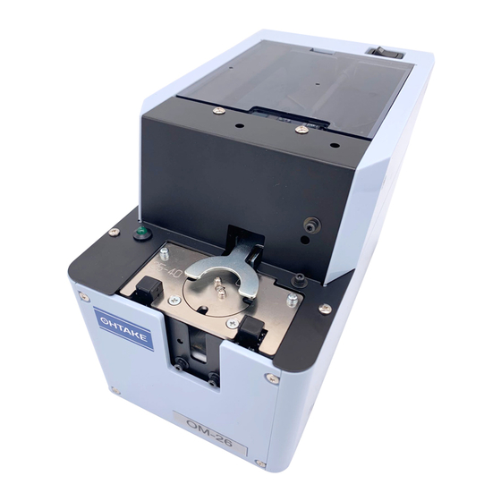
Automatic Screw Feeder
QUICHER
OM-26R
NSRI Type
Operation Manual
Operation Manual
Read these instructions for the proper use of this machine.
・ Read these instructions for the proper use of this machine.
After having read these instructions, keep them in a convenient place so you
・ After having read these instructions, keep them in a convenient
or the operator can refer to them whenever necessary.
place so you or the operator can refer to them whenever necessary.
ATTENTION : www.ohtake-root.co.jp is the only web site associated with our company.
We do not have any branches in China.
www.ohtake-root.co.jp
www.ohtake-root.co.jp
Automatic Screw Feeder
Series
(Maintenance)
HP
自動ネジ供給機
OMR1MA02bM
OMR1MA02
NSIR MAE01
Advertisement
Table of Contents

Related Manuals for OHTAKE OM-26R Series


Summary of Contents for OHTAKE OM-26R Series
- Page 1 ATTENTION : www.ohtake-root.co.jp is the only web site associated with our company. We do not have any branches in China.
-
Page 2: Table Of Contents
7. PARTS ADJUSTMENTS AND REPLACEMENTS ----- 15 1.OVERVIEW OF THIS MACHINE Thank you very much for selecting our Automatic Screw Feeder "OM-26R series". This machine, with the screwing robot, can line up screws (M-2, M-6) and supplies them continuously to help make screw fastening work efficient. -
Page 3: Operating Precautions
3.OPERATING PRECAUTIONS This manual contains safety alert symbols and signal words to help prevent injuries to the user or damage to property. ◎ Indications This indicates there is a chance of death, serious injury or fire if the instructions WARNING are not followed. - Page 4 WARNING Do not disassemble the AC adapter as there is a risk of electric shock, fire or malfunction. Do not damage, alter or change the power cord. Do not place heavy objects on the cord. Do not pull hard on the cord or twist the cord as it could be damaged, thereby causing a risk of fire or electric shock.
- Page 5 CAUTION Use only the AC adpater supplied with this machine otherwise it may result in a fire or electric shock. Do not install this machine in an unstable location otherwise it may fall causing damage or injury. Always operate the machine with the upper cover in place, otherwise it may result in injury. Do not allow any foreign material to enter the machine while in operation.
-
Page 6: Names Of Machine Parts
4.NAMES OF MACHINE PARTS Power switch Top lid Rail fixing bolt Holding plate Escaper guide Front cover LED screw indicator Front lower cover Holding plate adjusting bolt Light-emitting Light-receiving Holding plate sensor sensor Escaper fixing bolt Sensor bracket Escaper assembly fixing bolts (1 left / 1 right) -... - Page 7 Rear cover Scraper-left Scooping hopper Brush Scraper-right Rail assembly Frequency adjusting knob Amplitude adjusting knob Timer adjusting knob Signal line out Passing plate DC jack - 6 -...
-
Page 8: Adjustments And Checks Before Use
5.ADJUSTMENTS AND CHECKS BEFORE USE 5-1.Checking the model number of the main body Identification stamp Check if the machine has the parts which match the nominal diameter of the screws to be loaded. Check the model number of the rail, escaper, robot es- caper guide, and passing plate by referring to the following table. - Page 9 5-2.Basic operations ○Loading the screws ・Turn the power switch ON and OFF so that the brush stops vertically above the rail. ・Open the top cover and load screws on the left and right side of the rail evenly. ・Do not load screws above the surface of the rail. ・Be sure to determine the screw load by observing the machine while it is in operation.
- Page 10 ○Pick uping Screws ○Action of the escaper ・Pick up the screws at the stopper with the screwdriver on the robot. Use the bit guide to put the screwdriver down vertically into the screwhead's LED screw indicator slots. ねじ取出し部 Escaper ・When the screwdriver is inserted into the screwhead slots, be careful that no contact is made with the escaper or that the screw is not struck forcefully.
- Page 11 5-3.Adjusting the brush height Turn On and Off the power switch to put the brush Turn OFF the power switch before starting replacement and bristles in a horizontal position towards the left adjustment. side. Load the screws into the scooping hopper, turn ON and OFF the power switch so that screws are alligned into the rail groove.
- Page 12 5- 4.Checking and adjusting the rail vibration The amplitude and frequency of the rail vibration can be adjusted. The vibration has been adjusted at the factory for screws that correspond with the rail. Put some screws into the rail and turn the power on. If they are delivered smoothly, there is no need for adjustment.
- Page 13 5-5.Check and adjust the front and rear sides of the rail Rail fixing bolt Turn OFF the power switch before starting replacement and adjustment. ・If the rail comes into contact with the escaper, or the clearance between the rail and escaper is too large, loosen the rail fixing bolt, hold the rail groove and adjust the rail assembly either backward or forward.
- Page 14 5-7.Check and adjust the passing plate Turn OFF the power switch before starting replacement and adjustment. ・Check that the passing plate is adjusted to a height that permits loaded screws to pass just within the limit. Passing plate ・If the passing plate is too low, screws cannot pass. If the passing plate attaching bolt is too high, it will hamper a smooth transport of the screws.
- Page 15 5-9.Check and adjust the timer The screw transport feed differs depending on screw type. This machine can make screw unloading smooth through timer adjustment. For screws with a low transport speed, set the timer long. For screws with a high transport speed, set the timer short.
-
Page 16: Maintenance
6.MAINTENANCE A dirty rail groove may interfere with the screw transport speed. Clean the dirty rail with a soft, clean cloth dipped in alcohol. If cleaning is difficult, remove the rail from the machine and clean the rail groove. Refer to the next section under『7-1 Replacing the rail assembly』 for replacing. Before removing the rail from the machine, be sure to turn off the power supply and take the screws out of the hopper. - Page 17 7-1.Replacing the rail assembly Turn OFF the power switch before starting replacement and adjustment. Before replacing, remove all the screws from the hopper, the rail, and the escaper. The rail assembly of this machine can be easily replaced. If there is any dirt or flaw on the rail groove that prevents a smooth ①...
- Page 18 7-2.Replacing and adjustment of the escaper Names of the parts Turn OFF the power switch before replacing. Holding plate Robot escaper guide Turn ON the power switch when adjustments are necessary. Before replacing, remove all the screws from the hopper, the rail, and the escaper.
- Page 19 ③ Check the position of the parts for smooth delivery of the screws. Check that the clearances between the outside edges of the rail and the robot escaper guide-right and left are almost even. If they are in contact, the screws cannot be delivered. If there is too much clearance, on either side, screws may fall into the machine.
- Page 20 ④ Adjust the escaper notch position. Turn the power switch ON while covering the sensor light axis with a small piece of paper. When the power is ON, the screw sensor LED lights up and the escaper rotates around, to the starting point.(Reference point run.) When the escaper stops, loosen the fixing screws and adjust the escaper by hand so that an escaper notch and the rail groove align.
- Page 21 7-3.Checking and adjusting the sensor Front sensor Attach while ajusting the height Usually, there is no need to adjust the sensor as it was done when assembled in the factory. Front sensor The following are irregular situations that require adjustment: bracket -There is no screw at the pick up spot but, the LED is on and the escaper attaching screw...
- Page 22 7- 4.Replacing the Passing Plate Passing plate attaching screw Turn OFF the power switch before starting replacement and Passing plate adjustment. Use the passing plate, rail and escaper that correspond with the di- ameter of the screws to be used. Remove the passing plate.
- Page 23 7-6.Replacing the driving belt Turn OFF the power switch before starting replacement and adjustment. If the driving belt is worn, cut or slips while in use, replace it with a new one. ・Turn the power OFF and remove all covers. ・Remove the driving belt from the pulley by using a screwdriver to pry it off.
- Page 24 7-7.Replacing the Main Motor Turn OFF the power switch before starting replacement and adjustment. Remove the front cover and the LED connector. When the motor is damaged, replace it with a new one. ① Remove the bottom front cover from the main body. ①...
- Page 25 ⑤ Using the accompanying hex wrench, loosen the 2 hex head bolts from the driving pulley and remove it. If the bolts are hard to access, rotate the motor pulley with the hex wrench. ⑥ Remove the motor attaching screws. ⑤...
-
Page 26: Application With Robotic System
8. Application with Robotic System 8 - 1.External Output Signals The wires coming out from the back of the machine serves as the detection of presence of screws on the rotational escaper, which shall be used with automatic assembly machines or external screw counters. -
Page 27: Miscellaneous
. Installation with Robotic System 8 - 2 Fixing When installed with a robotic assembly, the screw feeder shall be method fastened by lower edges of the cover. (Please refer to diagram on the right side) Fastening screws on bottom edge of the cover can be used for this purpose as well. - Page 28 9 - 2.Screw quantity monitoring sensor (Optional) Screw onto the top lid. There is, as an optional attachment, a sensor which monitors the quantity of screws remaining in the scooping hopper. Put the harness through the notch With this attachment connected to the signal line, you can set the sensor to at the back of the top lid.
-
Page 29: Troubleshooting
10.TROUBLESHOOTING For safety, always unplug the AC adapter from the wall outlet before making any adjustments. Trouble Cause Corrective measures The machine does not operate though ・Power is not supplied. ・Check the connection of the power the power switch is turned ON. supply of the AC power adapter. - Page 30 Trouble Cause Corrective Measure Screws do not flow. ・Screws in an abnormal position in the ・Adjust the brush. passing plate cannot be swept away ・Adjust the passing plate. with the brush. If a proper amount of screws are loaded into the scooping hopper, the status may be improved.
- Page 31 Trouble Cause Corrective Measure A s c r e w h a s f a l l e n i n t o t h e r a i l ・Screws with a smaller diameter than the ・Use screws with the specified nominal groove.
- Page 32 Trouble Cause Corrective Measure Screws tend to pass ・The passing plate is not adjusted ・Adjust the passing plate. through the passing plate in an ab- properly. normal position. The axis of the screw thread tends to ・Too many screws are in the scooping ・Reduce the quantity of screws to enter the passing plate.
- Page 33 Trouble Cause Corrective Measure The scooping operation does not ・The timer knob is not properly adjusted. ・Readjust the timer knob. stop though a screw is at the pick up site. The escaper operation does not stop ・The sensor does not detect a screw. ・Readjust the voltage of the sensor.
- Page 34 Trouble Cause Corrective Measure The escaper does not rotate when ・ Undesired objects blocking front screw ・ Make sure there are no debris or no screws are present, although the sensor. other indicator light is on. objects present in the sensor brackets. ・...
- Page 35 ≪ What to do if the rail does not vibrate or vibration is weak ≫ The possible causes for the above symptoms, which are particularly frequently asked, are listed below. Please check. ※ Since there is no margin in the length of the wiring inside the machine, when removing the main unit cover, please work carefully so as not to cut the wiring by mistake.
- Page 36 ・ Method of adjusting clearance between solenoid and Method of adjusting clearance between electromagnet adsorption plate. solenoid and electromagnet adsorption Electromagnetic plate. ① Loosen the solenoid fixing screws. attracting piece Clearance Loosen the solenoid fixing screws. (From the back side) (From the back side) ②...
- Page 37 Vibration will be weakened if foreign objects are caught between the vibrating part and Cause Corrective Measure the non-vibrating fixed part. ◎ Foreign matter is caught under or around the rail support plate. Please remove the trapped foreign matter. Vibration will be weakened if foreign objects are caught between the vibrating part and the non-vibrating fixed part.
- Page 38 Scraper Cause Corrective Measure Passing plate is in contact with rail. Adjust the position of the passing ◎ Passing plate is in contact with rail. Adjust the position of the passing plate. If the passing plate is in contact with the rail, plate.
-
Page 39: Specifications
11.SPECIFICATIONS [CAUTION] ・This machine accepts only steel screws. Plastic or stainless screws cannnot Input:AC100~240V 50/60Hz be used. Output:DC15V 1A (switching type) ・Check if the axis diameter of the loaded screw matches the rail groove width. 119(W) × 226(D) × 152(H) (mm) ・Within The range of screw size and length below,there may be instances of Approx. - Page 40 Notes : - In the Exchange kit ordered, Rail assembly, length( Escaper, Robot escaper guide and Passing (φ ) (φ ) (φ ) (mm) plate are included. φ φ 1.9~2.1 2.4~6 2.4~10 0.35~6 2.6~ φ φ - Please contact us by " ~ SET" type when 2.2~2.4 2.7~6 2.7~10...
-
Page 41: External Dimensions
A寸法 ネジ呼び径 の目安 12. EXTERNAL DIMENSIONS φ φ φ φ φ φ φ φ φ φ POWER φ φ φ φ φ φ DC jack Signal line out Unit : mm ※ Height to top of escaper - 40 -... -
Page 42: Warranty
13. WARRANTY For users within Japan, the effective term of warranty is 6 months after delivery. Such warranty will not be applicable to purchases or users outside of Japan. If any troubles should occur, please contact your dealer. After the warranty period, repair services will be completed. In the following cases, the purchaser shall pay for parts and labor regardless of the terms of warranty: ... - Page 43 - 42 -...
- Page 44 Fax +81-191-24-3145 Fax +81-191-24-3145 「Quicher」 「OHTAKE」 「OHTAKE ・ ROOT KOGYO」 are trademarks or/and registered trademarks of OHTAKE ・ ROOT KOGYO CO.LTD. 「Quicher( クイッチャー)」 「OHTAKE」 「OHTAKE ・ ROOT KOGYO」 は、 株式会社 大武 ・ ルート工業の商標又は登録商標です。 The specifications and/or design may be altered, without notice, whenever there are changes or improvements.
Need help?
Do you have a question about the OM-26R Series and is the answer not in the manual?
Questions and answers