Advertisement
TRC ELECTRONICS, INC.
Providing exceptional customer service since 1982
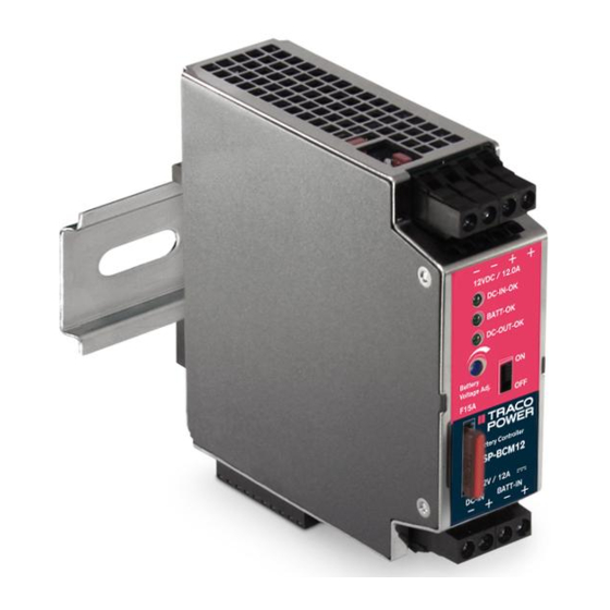
Battery Controller Module
Operating Instruction Manual
http://www.tracopower.com
TRC ELECTRONICS, INC.
TSP-BCM12 / -BCM24 / -BCM24A / -BCM48 / -BCM48A
1.888.612.9514
Operating Instruction Manual
TRACO POWER Battery Controller Series
TSP-BCM12
TSP-BCM24, TSP-BCM24A
TSP-BCM48, TSP-BCM48A
www.trcelectronics.com/traco-power
Page 1 of 7
Advertisement
Table of Contents

Summary of Contents for TRC TSP-BCM12
- Page 1 Operating Instruction Manual TRACO POWER Battery Controller Series TSP-BCM12 / -BCM24 / -BCM24A / -BCM48 / -BCM48A TRC ELECTRONICS, INC. Providing exceptional customer service since 1982 Battery Controller Module TSP-BCM12 TSP-BCM24, TSP-BCM24A TSP-BCM48, TSP-BCM48A Operating Instruction Manual http://www.tracopower.com Page 1 of 7 TRC ELECTRONICS, INC.
-
Page 2: Mechanical Mounting
1. Mechanical Mounting The TSP-BCM12 as well as the TSP-BCM24, TSP-BCM24A, TSP-BCM48 and TSP-BCM48A are “Built in Devices”, and must be mounted into an electrical rack which must provide protection against access to dangerous voltages, hot devices and be resistant to flammability and causing fire hazards. - Page 3 Configure the BCM module to your actual configuration of power supply TSP 090-124, TSP 090-148, TSP 180-124, TSP 180-148, TSP 360-124, TSP 360-148, TSP 600-124 or TSP 600-148 in combination with TSP-BCM12, TSP-BCM24(A) or BCM48(A) by choosing the jumper position J6 as described in paragraph 3.5.
- Page 4 The floating DC-OUT-OK (see Fig. 2.1 Connector J5, pin 5 & pin 6) is available to monitor if the TSP-BCM12, TSP-BCM24(A) or TSP-BCM48(A) provides an output voltage. If the output voltage on the TSP-BCM24 or TSP-BCM24A is present, the relay contact (30Vdc / 0.6A or 60Vdc / 0.3A) is closed.
-
Page 5: Remote On/Off
Connector J5 pin 7 and Connector J5, pin 8 by use of a switch has to be made. At open connection between J5 pin 7 and J5 pin 8 the device is providing the adjusted output voltage. On the TSP-BCM12 TSP-BCM24(A) as well as theTSP-BCM48(A) a switch is available to switch off the system on site (in the control cabinet). - Page 6 Operating Instruction Manual TRACO POWER Battery Controller Series TSP-BCM12 / -BCM24 / -BCM24A / -BCM48 / -BCM48A TRC ELECTRONICS, INC. Providing exceptional customer service since 1982 TSP-BCM12 TSP power supply Jumper position BCM Module Input Current Limitation Power Supply Type...
- Page 7 Operating Instruction Manual TRACO POWER Battery Controller Series TSP-BCM12 / -BCM24 / -BCM24A / -BCM48 / -BCM48A TRC ELECTRONICS, INC. Providing exceptional customer service since 1982 5. Wall mounting brackets (TSP-WMK01) for TSP-BCM12, TSP-BCM24, TSP- BCM24A, TSP-BCM48 & TSP-BCM48A TRC ELECTRONICS, INC.
Need help?
Do you have a question about the TSP-BCM12 and is the answer not in the manual?
Questions and answers