
Related Manuals for RFDATATECH ZRT Series

Summary of Contents for RFDATATECH ZRT Series
- Page 1 ZRT SERIES RADIO MODEMS SETUP, INSTALLATION & OPERATING MANUAL ZRT Manual Page 1 of 37 Rev. J – 11 September 2008...
- Page 2 ZRT Manual Page 2 of 37 Rev. J – 11 September 2008...
-
Page 3: Table Of Contents
CONTENTS INTRODUCTION ..................4 PRODUCTS COVERED......................4 IMPORTANT NOTICES......................4 PRODUCT OVERVIEW................5 GENERAL ..........................5 TRANSMITTER........................5 RECEIVER..........................5 MPU CONTROL ........................6 PROGRAMMING & CONFIGURATION................6 SOFT MODEM: ........................6 MODES OF OPERATION .......................6 HANDSHAKING........................6 ADDITIONAL FEATURES...................... 7 SPECIFICATIONS ..................8 TECHNICAL SPECIFICATIONS ....................8 APPROVALS AND LICENSING ..................10 PRE-PROGRAMMED CHANNEL PLANS .......... -
Page 4: Introduction
INTRODUCTION PRODUCTS COVERED This manual covers the ZRT Series of low cost, high performance radio modems designed for data applications in commercial and industrial systems. The ZRT is an advanced, simplex/half-duplex, data radio for transmission of serial data. Versions are available with three different serial port configurations:- A true RS232 interface full handshaking. -
Page 5: Product Overview
PRODUCT OVERVIEW GENERAL The ZRT Series has been designed as a range of high specification, low cost radio modems for stand alone applications or for integration into OEM products. Through the use of advanced DSP technology, the design has been optimised for reliability and low current consumption, making the ZRT suitable for operation on remote sites without mains power. -
Page 6: Mpu Control
MPU CONTROL The Microprocessor (MPU) is the heart of the product and at the centre is a 128k flash microprocessor that controls all the interface circuits to the radio module and external input/outputs. As well as the control functions, the processor provides DSP functionality that enables modem operation between 150 and 9,600bps. -
Page 7: Additional Features
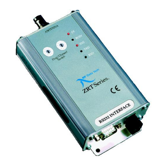
ADDITIONAL FEATURES The ZRT incorporates the following additional features which enhance the usability of the product and assist with the operation and maintenance of systems using the product:- 2.9.1 Status LEDs: The ZRT Radio Modems have a number of front panel LED’s to enable the operator to see at a glance the status of the product and the serial data port. -
Page 8: Specifications
SPECIFICATIONS TECHNICAL SPECIFICATIONS 3.1.1 General Frequency Range: ZRT169/170 138 - 175MHz ZRT225 175 - 225MHz ZRT450/470 406 - 512MHz ZRT869 863 - 870MHz (50MHz – 950MHz to special order) Power Requirements: 12VDC (10V – 15.5DC) Standby: <75uA Receiver on & decoding: <70mA Transmitting: 300mA to 2.1A dependent on Tx power... - Page 9 3.1.3 Receiver Sensitivity: 0.25uV (-119dBm) for 12dB SINAD de-emphasised 0.355uV (-117dBm) for 12dB SINAD flat Bandwidth: 5MHz without re-alignment 10MHz without re-alignment 20MHz without re-alignment Spurious Response: ZRT 169/450/869 >65dB ZRT 170/225/470 >80dB Blocking: ZRT 169/450/869 >85dBuV ZRT 170/225/470 >90dBuV Intermodulation: ZRT 169/450/869 >60dB...
-
Page 10: Approvals And Licensing
The unit meets the relevant requirements of this Safety specification. 3.2.3 European Declaration of Conformance Hereby, RF DataTech declares that the ZRT Series of Radio Modems is in compliance with the essential requirements and other relevant provisions of Directive 1999/5/EC. 3.2.4 USA FCC Part 90 &... - Page 11 RF EXPOSURE WARNING: To satisfy FCC/IC RF exposure requirements for mobile transmitting devices, a separation distance must be maintained between the antenna connected to this device and persons during device operation. To ensure compliance, operations at closer than these distances are not recommended. The following table show the minimum distance for different gain antennas: Antenna Gain Minimum Separation Distance...
-
Page 12: Pre-Programmed Channel Plans
PRE-PROGRAMMED CHANNEL PLANS Using the PC configuration software, the ZRT can be programmed with a number of user specified or standard channel plans. Standard plans currently include all UK MPT1411 or MPT1329 channels. Further standard channel plans may become available in later releases of the configuration software. - Page 13 457.98125 463.48125 457.99375 463.49375 458.00625 463.50625 458.01875 463.51875 458.03125 463.53125 458.04375 463.54375 458.05625 463.55625 458.06875 463.56875 458.08125 463.58125 458.09375 463.59375 458.10625 463.60625 458.11875 463.61875 458.13125 463.63125 458.14375 463.64375 458.15625 463.65625 458.16875 463.66875 458.18125 463.68125 458.19375 463.69375 458.20625 463.70625 458.21875 463.71875 458.23125 463.73125 458.24375...
-
Page 14: Mpt1329 Channels
UK MPT1329 CHANNELS The ZRT can be programmed to operate on the full MPT1329 band of channels with access to channels 26, 27 & 32 denied, in line with MPT1329 band plan. The radio should be programmed for a maximum power level of 500mW. CHANNEL FREQUENCY 458.5000 Guard Ch. -
Page 15: Setup & Interfacing
The exploded view shows the main components of the radio modem. There are no user adjustments or settings which require removal of the covers. INTERFACE PORT PIN CONNECTIONS The ZRT Series is equipped with a 9 way female D connector for the traffic interface. The pins of this connector are allocated as follows:- 5.2.1 RS232-Only (Full Handshaking) and 5V TTL versions 1. - Page 16 5.2.2 RS232/RS422/RS485 Versions The RS232/RS422/RS485 versions of the ZRT may be software programmed to have either an RS232 or an RS422/RS485 compatible interface. To allow programming without an interface adapter, a radio programmed for RS422/RS485 operation will switch back to RS232 operation if the front panel rotary switches are set to position 00 to select programming mode.
-
Page 17: 12Vdc Power
The DTR input has a threshold of approximately +1.5V with respect to ground, it may be used with a standard RS232 level signal or a TTL level signal in either RS232 or RS485 mode, the signal is active high in both cases. 12VDC POWER A nominal 12VDC (9.6 –... -
Page 18: Time-Out-Timer
TIME-OUT-TIMER The transmitter within the ZRT has a time-out timer which allows the maximum continuous transmission time to be set in order to prevent channel blocking due to a host fault. The timer works in all modes (external/internal modem) and is programmable in one second steps between 0 and 255 seconds. -
Page 19: Radio Data Formats
If compatibility with other radios is not required, the use of the synchronous mode is recommended, as this will give best link performance. 5.10 RADIO DATA FORMATS The data rate over the air can be set up independently of the rate set for the serial interface, but the over-air rate should be set either at the same speed or a lower speed than the serial interface rate. - Page 20 5.13.2 Handshaking on RS232-Only (Full Handshaking) and TTL versions The RS232 Only (Full Handshaking) and TTL versions can be programmed either to use RTS/CTS handshaking to initiate transmission, or to transmit automatically whenever data is present at the serial input. In the latter mode CTS is still operated to implement flow control but can be ignored unless message sizes exceed 1k byte and the serial port baud rate is higher than the radio signal baud rate.
-
Page 21: Traffic Protocol & Routing Modes
The ZRT can support “Store & Forward” repeater operation to cope with situations where the direct communication between sites is not possible due to range or terrain. The ZRT series supports up to six repeaters within one link, although the more repeaters used, the greater the signal strength has to be at each receiver, as there will be some accumulative degradation over the whole link. -
Page 22: Transmit & Receive Timing
5.15 TRANSMIT & RECEIVE TIMING The ZRT only operates in a simplex or semi-duplex mode. In simplex mode the receive and transmit frequencies are the same, whereas in the semi-duplex mode they are different. In either mode data is only sent in one direction at a time as the radios do not have separate synthesisers for transmit and receive. - Page 23 5.15.1 Receive To Transmit Switching Time When using the internal modem the action that initiates transmission can be either receipt of a character at the serial port or the operation of RTS. These examples use the first mode. The radio does nothing until the stop bit of the first character for transmission has been received, the transmitter is then started: The time delay between receipt of the stop bit for the first character to be transmitted at the...
- Page 24 5.15.2 Message Duration The time taken to transmit a message can be simply derived by multiplying the number of characters in a message by the values given in table C making any appropriate corrections for data format. The exception is 9600 baud where extra synchronisation sent during the message must be taken into account, 8 synchronisation bits lasting a total of 0.833ms are sent after every eighth message character.
-
Page 25: Power Consumption
5.16 POWER CONSUMPTION The ZRT is a very low power product and is ideal for operation from batteries with solar power backup. The information below is intended to help the user decide on the best battery and solar cell size for operation at non powered sites. 5.16.1 Transmitter RF power verses current TX Power 500mW 200mW 100mW 50mW... -
Page 26: Status Leds
5.19 STATUS LEDS The ZRT has a number of LEDs to enable the operator to see at a glance the status of the product and the serial port:- RF Carrier Detect/Busy Transmit System Receive Data Transmit Data 5.19.1 System LED With the Exception of the System LED the remainder are self explanatory. -
Page 27: Store & Forward
STORE & FORWARD STORE & FORWARD BASED ON CLIENT PROTOCOL. To conserve valuable air time and avoid the possibility of collisions due to coverage overlaps with other repeaters transmitting at the same time, only messages that require forwarding by specific repeaters are re-transmitted when the ZRT is used in “Store & Forward” mode. This is achieved by stripping out the addresses of incoming serial messages, comparing the address with the list of outstation addresses stored in the unit and routing the messages accordingly. - Page 28 If a radio is specified as a relay in a link, any locally connected Modbus devices will not be aware of communications that take place as no activity occurs on the serial port in this state. This may cause problems however if more than one master exists in a system as a radio that is being used as a link in a relay is not available to transmit messages.
-
Page 29: Rft Routing Protocol
6.2.5 Timeouts in MODBUS Modes When a transmission from a master station radio is made in Modbus mode the radio will calculate a timeout for a reply, this calculation is based on many configuration parameters including the radio baud rate, lead in delay, host inactivity time, maximum message length, power save timing etc. - Page 30 The position of the address in the protocol field is specified using the “ADDRESS OFFSET” parameter in the setup programme. A setting of 0 specifies zero offset, i.e. the address is the first byte in the message, an offset of 6 specifies the 7th message byte and so on. 16 bit addressing or more is not supported as a maximum of only 256 destinations can be supported by the routing table.
- Page 31 Note that if “DTR SHUTDOWN” is enabled a radio remains completely shut down while DTR is inactive, it will not wake up according to the power save timer to see if any incoming messages are present. This mode should therefore only be used in conjunction with real time message scheduling.
-
Page 32: Installation
INSTALLATION INTRODUCTION Correct installation of the ZRT radios should ensure reliable data communications for many years. The most important installation points to remember are:- Suitable antenna system mounted at the correct height & polarisation to achieve the required distance. Reliable power supply capable of supplying the correct voltage and current. Correct installation for the environment. -
Page 33: Antennas, Coax Feeders & Peripherals
ANTENNAS, COAX FEEDERS & PERIPHERALS 7.4.1 Antennas Apart from the radio modem, the antenna is probably the most important part of the system. The wrong choice or a bad installation will almost certainly impede the product’s performance. Depending on the application either an omni-directional or directional antenna will be required. - Page 34 7.4.6 Antenna Mounting Location: The antenna should be mounted in a clear area, as far away as possible from obstructions such as metal constructions, buildings and foliage. Height: The ZRT operates in the UHF band, which requires near line of sight communication.
-
Page 35: Mounting & Installation
If IP65, 67 or 68 is required then an additional enclosure will be required. A number of suitable enclosures are available as options. FIXING DETAILS ANTENNA BUSY Prog/Channel Switch ZRT Series. INPUT -12V+ ZRT Manual Page 35 of 37 Rev. J – 11 September 2008... - Page 36 ZRT Manual Page 36 of 37 Rev. J – 11 September 2008...
- Page 37 R.F. Technologies Ltd 27 – 29 New Road Hextable Kent BR8 7LS Tel: +44 (0) 1322 614 313 Fax: +44 (0) 1322 614 289 E-Mail: info@rfdatatech.co.uk ADDITIONAL PRODUCT DATA www.rfdatatech.co.uk ZRT Manual Page 37 of 37 Rev. J – 11 September 2008...
Need help?
Do you have a question about the ZRT Series and is the answer not in the manual?
Questions and answers