
Related Manuals for Hewalex GH26-P09


Summary of Contents for Hewalex GH26-P09
- Page 1 USER MANUAL OF AN INDEPENDENT REGULATION BLOCK GH26-P09 GH26-P09A Controller of a solar collector system applicable from version 0.1a...
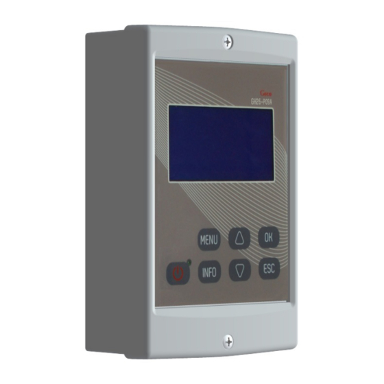
- Page 2 Controller description The GH26 controller is a device designed and made for controlling solar collector systems. The product has been made with the use of modern and reliable microprocessor technology. Design of the controller is modern and the controller itself is very user-friendly thanks to the use of a user panel with a clear keyboard and an LCD display. The GH26 controller has to be mounted on the wall.
- Page 3 ATTENTION ! If a power cord gets damaged it should be substituted with new one. For specific installation schemes with the description of connecting devices to the controller, see section 4 (Installation schemes). Switching on and using the controller 3.1 First switch on of the controller Upon connecting the controller to a power source it will be switched on in the stand-by mode and a diode will get lit.
- Page 4 If the controller has been switched into regular operation mode, you can access the main controller MENU by pressing the key. Navigation keys serve the purpose of selecting some options. Then you can enter the selected option by pressing the key.
- Page 5 4.3 Tap water heating system - controlling solar collector pump, circulation pump and a boiler - scheme no 3 Controlling the P collector pump Similarly as in scheme no 1 - description in point 4.1. Controlling the C circulation pump Similarly as in scheme no 2 - description in point 4.2.
- Page 6 ATTENTION ! An additional relay adjusted to the power consumption of the electrical heater is needed to switch the heater on. Fig. 6. Schematic and electrical diagram of installation no 4. 4.5 Tap water heating system - controlling solar collector pump, circulation pump and a heat pump – scheme no 5 Controlling the P collector pump Similarly as in scheme no 1 - description in point 4.1.
- Page 7 Fig. 8. Schematic and electrical diagram of installation no 6. 4.7 Double heater system - makes it possible to provide additional solar energy for the boiler heater with the use of a mixing pump - scheme no 7 Controlling the P collector pump Similarly as in scheme no 1 - description in point 4.1.
- Page 8 4.9 Tap and pool water heating with the use of a three-way valve, controlling operation of the pool water pump - scheme no 9 Controlling collector pump and U three-way valve – selected priority: B > A Supplying solar energy to B heater is analogical as in the scheme no 1 and has been described in point 4.1. The A pool constitutes yet another heat receiver.
- Page 9 4.11 Double heater system with the use of a three-way valve, controlling operation of the circulation pump - scheme no 11 Controlling collector pump and U three-way valve Similarly as in scheme no 9 - description in point 4.9. The A heater plays the role of A pool in the described scheme. Controlling the C circulation pump Similarly as in scheme no 2 - description in point 4.2.
- Page 10 Fig. 15. Schematic and electrical diagram of installation no 13. 4.14 System for heating a combi heater with solar collector, an electrical boiler or liquid-fuel boiler and a solid-fuel boiler - scheme no 14 Controlling the P collector pump Similarly as in scheme no 1 - description in point 4.1. Controlling the K boiler Similarly as in scheme no 3 - description in point 4.3.
- Page 11 reaches the set value of “MaxTemp. T2 OFF collector’s pump”. Additionally, in order to avoid unstable pump operation when the temperature on the temperature sensor changes, switch on and switch off hysteresis has been used. ATTENTION! In case of simultaneous operation of the P pump and the K pump, the current value of the PWM control signal is determined by the higher temperature difference.
- Page 12 Fig. 19. Schematic and electrical diagram of installation no 17 4.18 Tap water heating system – controlling solar collector pump, solar energy heating for the boiler heater with the use of a pump and controlling the operation of fireplace or solid-fuel boiler pump – scheme no 18 Controlling the P collector pump Similarly as in scheme no 1 –...
- Page 13 Parameter settings 5.1 Control parameters This option makes it possible to change the value of parameters available in the selected installation scheme. In order to change parameters: Press the following key combination: starting point - MAIN SCREEN: entry into the MENU , get to the option named Parameters settings , enter the Parameter settings , get to the Control parameters option...
- Page 14 ATTENTION ! Leaving the field unchanged or entering wrong value does not affect the operation of the controller and the system (the controller reads the actual flow rate from the electronic flow meter). Measurement: Rotameter – cooperation with a mechanical flow meter (rotameter). The controller works with declared values (calculating power and energy outputs). ATTENTION ! The bottom of the rotameter float indicates the actual flow rate value.
- Page 15 This option allows setting brightness and back-light time for the display. In order to change parameters: Press the following key combination: starting point - MAIN SCREEN: enter the MENU with , get to the option named Controller settings with , enter the Controller settings menu with , get to the option named Display with , enter the Display option with...
- Page 16 In the Energy Statistics menu there is also a total energy counter. This counter sums all the produced energy. Statistics and total counter can be cleared any time. The clearing option can be found in the Energy Statistics menu and is available separately for the total counter and the statistics. In order to view or clear energy counters select the "Energy Statistics”...
-
Page 17: Electronic Flow Meter
Enabling the function Protection against Legionella causes periodic (once a week – from Sunday to Monday from 12.00 a.m. Protection against up to 6.00 a.m.) heating of water in the water heater up to temp. of 70C. After enabling the option the L symbol will be displayed Legionella on the main screen of the controller. - Page 18 II step – (When the T1-T2 > 50°C or T3-T2 > 50°C condition is fulfilled for another 10 minutes), the controller switches off the specific solar collector pump and generates a sound signal and displays the following message: LACK OF FLOW, FAILURE OF THE P OR K PUMP, AIR-LOCKED SYSTEM, BLOCKED FLOW. By pressing the key for acceptance the user will switch on the solar collector pump again.
Need help?
Do you have a question about the GH26-P09 and is the answer not in the manual?
Questions and answers