Advertisement
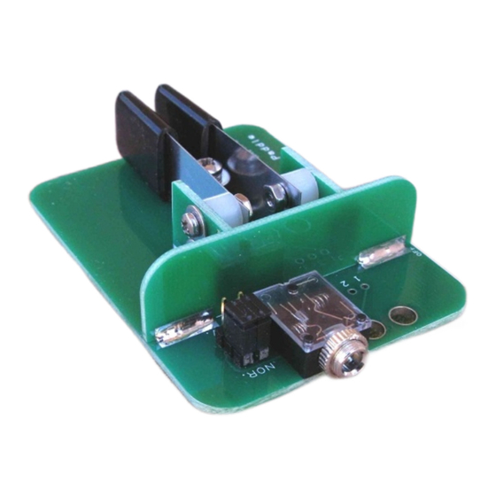
QRPGuys Iambic Mini Paddle w/Base
First, familiarize yourself with the parts and check for all the components. If a part is missing, please
contact us and we will send one. You must use
qrpguys.parts@gmail.com
to request a part.
Parts List
1 – QRPGuys Iambic Paddle w/Base PCB, 5 pieces
1 – 3.5mm stereo audio jack
2 – 3 position in-line header
2 – header jumper (Berg connector)
1 – 3.5mm stereo plug
2 – SS paddle leaf
1 – 4-40 x 3/8"L SS pan head Phillips screw
1 - #4 SS flat washer
1 - #4 SS lock washer
1 - #4 x .187"L nylon spacer
1 – 4-40 brass nut
4 – 2-56 x .375"L SS pan head Phillips screw
4 – 2-56 SS nut
4 - #2 SS flat washer
4 - #2 SS lock washer
4 - #2 x .187"L nylon spacer
1 - #2 x 3/4"L nylon spacer
1 – 2-56 x 1"L SS pan head Phillips screw
2 - 1/2" x 1" vinyl caplug
2 - 1/2" wide x 2"L plastic shim
1 – 4" x 1/8" black cable tie
4 – Silicone self-adhesive foot, 6mm
Even if you have done radio kit assembly before, please read through all the instructions before you
start. This kit is a little different, in that the mechanical components are the part of the printed circuit
board. The instructions give you the scope of the project and an understanding of the techniques we
have employed. You will be assembling the kit using five pieces of PCB material, and when assembled,
form the electrical connections. There are solder pads, registration marks, and letter coded parts, that
match each other. When you tack and solder the components it will make a sturdy mechanical and
electrical assembly.
Page 1 of 7
iambic_paddle_w-base_assy_021816.pdf
Advertisement
Table of Contents

Summary of Contents for QRPGuys Iambic Mini
- Page 1 You must use qrpguys.parts@gmail.com to request a part. Parts List 1 – QRPGuys Iambic Paddle w/Base PCB, 5 pieces 1 – 3.5mm stereo audio jack 2 – 3 position in-line header 2 – header jumper (Berg connector) 1 –...
- Page 2 Refer to the figure below for identification of the individual PCB parts. On all the mechanical assembly soldering you do, you will use the same technique. You tack a single tiny point first, and then check to see that it is square and aligned with the registration points.
- Page 3 Notice that the pieces are coded with letters that will match up when you have them in the correct alignment. The first two pieces to be joined are the backstop and the base. Attach the alignment gage to the base using a 4-40 screw and nut as shown in the figure below. Tighten the screw after you have placed the backstop against the gage and aligned it with the registration marks.
- Page 4 Use the same technique adding the leaf holders. Space the two leaf holders with the #2 x 3/4” long #2 nylon spacer, 2-56 x 1” long screw and one of the 2-56 nuts. Match the registration letters and alignment marks. Slide the leaf holder assembly between the alignment gage, up against the backstop and light tack the pad between the base and paddle leafs.
- Page 5 This completes soldering the mechanical pieces. Continue the building the kit by soldering the electrical components. Use the figure below for the part placement. Parts placement figure Install the two 3 pin headers. Install J1, the 3.5mm audio jack where indicated. The attached cable for input to your transmitter is optional.
- Page 6 Assembling the paddle lever components: It’s a good idea to assemble the hardware over a cookie sheet. Any hardware is difficult to find if dropped. Secure the paddle leaves to the holders using the hardware as shown. The hardware is small but with some patience and tweezers, can be assembled.
- Page 7 Schematic: Notes: ________________________________________________________ ________________________________________________________ ________________________________________________________ ________________________________________________________ ________________________________________________________ ________________________________________________________ ________________________________________________________ ________________________________________________________ ________________________________________________________ ________________________________________________________ Page 7 of 7 iambic_paddle_w-base_assy_021816.pdf...
Need help?
Do you have a question about the Iambic Mini and is the answer not in the manual?
Questions and answers