
Summary of Contents for EarthLinked CCA Series
- Page 1 ® EarthLinked CCA Series Cased Coils Installation Manual CCA-410-IM (03/15) Page 1...
-
Page 2: Table Of Contents
Cased Coil Placement ......................... 7 Refrigeration ..........................9 Line Set ..........................9 TXV Kit..........................11 Airflow ............................20 Appendix A – CCA Series (CE) Supplemental Installation Instructions ........... 21 Appendix B – CCA Series (CE) Parts List ..................24 CCA-410-IM (03/15) Page 2... - Page 3 List of Figures Figure 1. Heat/Cool and Cool Only Component Matchup ................. 6 Figure 2. Heat Only Component Matchup ....................6 Figure 3. General Layout of System Components ................... 7 Figure 4. General Air Handler Physical Dimensions ................8 Figure 5. Line Set Sizes .......................... 9 Figure 6.
-
Page 4: Model Nomenclature
Earthlinked Technologies shall not be liable for any defect, unsatisfactory performance, damage or loss, whether direct or consequential, relative to the design, manufacture, construction, application or installation of the field specified components. -
Page 5: Safety
Equipment Manuals The following is a listing of the equipment installation manuals that are provided with each component ® specified for this EarthLinked system. IMPORTANT! Read and follow all installation instructions in these manuals, ®... -
Page 6: Installation
Installation Component Matching CCA Series Cased Coils are ready for vertical installation as shipped. Field conversion to horizontal requires no additional components. The CCA Series Cased Coils are manufactured for vertical and horizontal applications. Heat/Cool and Cool Only (Model CCA-00XX): These cased coils are equipped with a distributor designed for providing optimum performance in the cooling mode and the heating mode. -
Page 7: Cased Coil Placement
AND/OR PROPERTY DAMAGE, PERSONAL INJURY OR DEATH. Guidelines for the cased coil (or air handler) placement relative to the compressor unit and other ® EarthLinked system components are shown in Figure 3. Figure 3. General Layout of System Components CCA-410-IM (03/15) -
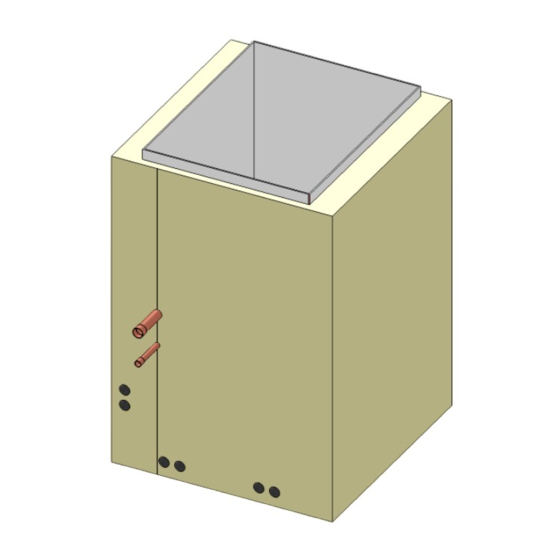
Page 8: Figure 4. General Air Handler Physical Dimensions
Dimensions for the cased coils are illustrated and listed in Figure 4. Cainet LIQ/VAP OUTLET NLET Heat/Cool, Compressor Heat Only Cool Only H x W x D W1 x D1 W2 x D2 Unit Model Model Model Inches Inches Inches Inches -018 CCA –... -
Page 9: Refrigeration
Refrigeration Line Set Line set sizes for CCA Series Cased Coils connecting to the matching compressor units are listed in ® ® Figure 5. Line set liquid and vapor lines are to be insulated with Armaflex , Insul-Lock or equivalent tubing insulation at least ½”... -
Page 10: Figure 6. Cased Coil And Air Handler Line Set Separation
Figure 6. Cased Coil and Air Handler Line Set Separation CCA-410-IM (03/15) Page 10... -
Page 11: Txv Kit
TXV Kit Introduction CCA Series cased coils that are intended for HEAT ONLY application are ready to install and make the refrigeration line set connection to the cased coil as shipped. CCA Series cased coils that are intended for HEAT/COOL or COOL ONLY applications, are shipped with the matching TXV Kit that must be field installed to enable operation of the system in the cool mode. -
Page 12: Figure 8A. Txv Control Installed Near Cased Coil (Vertical Application)
The TXV control box is field positioned external to the vertical (upflow or downflow) cased coil and fastened to a solid mounting surface immediately adjacent to the cased coil as shown typically in Figure 8a. Locate the TXV control box to allow a service access of at least 12 inches in front of the box to adjust the TXV control. -
Page 13: Figure 8B. Txv Control Installed Near Cased Coil (Horizontal Application)
For horizontal cased coil applications (left or right air flow), the TXV control box is field positioned external to the cased coil and can be fastened to a solid mounting surface immediately adjacent to the cased coil as shown typically in Figure 8b. Important! The TXV control box must be located no more than 3-1/2 feet from the suction tube stub out on the cased coil. -
Page 14: Figure 8C. Txv Control Box Dimensions
For mounting purposes, the physical dimensions for the TXV Control Box are shown in figure 8c. The preferred mounting position for the TXV Control Box is vertical with the liquid line tube connections on the bottom. However, as shown in Figure 8d, the Control Box can be mounted from vertical to any angle up to 90 degrees (horizontal). -
Page 15: Figure 8D. Txv Control Box Mounting Positions
Figure 8d. TXV Control Box Mounting Positions The following steps and positioning requirements apply to installing the TXV Control to the cased coil for vertical and horizontal applications. The vertical installation provides an illustrated example. Step 1: Relieve the nitrogen holding charge on the air handler using the valve on the liquid line stub out. Locate the TXV Control box within the 3-1/2 feet of the suction line stub out on the cased coil. -
Page 16: Figure 9. Positioning The Pressure Equalizer Tee
Step 2: Position the Pressure Equalizer Tee on the suction tube at least 10 inches downstream from the 90° ell as shown in Figure 9. Remove the core from Schrader valve on the Tee. Figure 9. Positioning the Pressure Equalizer Tee CCA-410-IM (03/15) Page 16... -
Page 17: Figure 10. Thermal Bulb Positioning
Step 3: The Thermal Bulb must be positioned and clamped to the suction tube as shown in the example illustrated in Figure 10. The Thermal Bulb and suction tube must be horizontal regardless of the cased coil application (vertical or horizontal). The Thermal Bulb must be positioned at the 3:00, 4:00, 8:00 or 9:00 positions on the suction tube, as illustrated in Figure 10. -
Page 18: Figure 11. Clamping The Thermal Bulb
Figure 11. Clamping the Thermal Bulb Figure 12. Insulating the Thermal Bulb CCA-410-IM (03/15) Page 18... -
Page 19: Figure 13. Txv Liquid Line Connections
Step 5: Measure and cut copper tubing to connect the liquid line from the TXV control box to the liquid line stub out on the cased coil as shown in Figures 7 and 13. Run the other liquid line from the connection on the TXV control box to the compressor unit, also shown in Figure 13. -
Page 20: Airflow
Airflow CCA Cased Coils are designed to operate at 400 cfm/Ton, nominal capacity. For system design purposes, Figure 14 provides the airflows for each CCA cased coil model and the associated coil pressure drops. Coil Pressure Drop, Cased Coil Model Airflow, cfm in W.C. -
Page 21: Appendix A - Cca Series (Ce) Supplemental Installation Instructions
Appendix A – CCA Series (CE) Supplemental Installation Instructions 1. Condensate Drain Preparation 2. Coil Installation 3. Coil Application – CCA Series (CE) • Vertical • Horizontal CCA-410-IM (03/15) Page 21... - Page 22 CCA-410-IM (03/15) Page 22...
- Page 23 CCA-410-IM (03/15) Page 23...
-
Page 24: Appendix B - Cca Series (Ce) Parts List
Appendix B – CCA Series (CE) Parts List CCA-410-IM (03/15) Page 24... - Page 25 CCA-410-IM (03/15) Page 25...
- Page 26 CCA-410-IM (03/15) Page 26...
Need help?
Do you have a question about the CCA Series and is the answer not in the manual?
Questions and answers