
Summary of Contents for Trinity POWERCUBE
- Page 1 SER'S ANUAL POWERCUBE Electrical System Monitor PowerCube PowerCube OWER OWER RS485 to RS485 to RS232 cable RS232 RS232...
- Page 2 POWERCUBE Electrical System Monitor This document contains the latest technical information about PowerCube which is a micro-controller based Electrical System Monitor. The product PowerCube is sophisticated electronic equipment, and the user is advised to read this User's Manual carefully before attempting to install or operate the equipment.
- Page 3 Trinity Dealer or Factory. You are responsible for all costs (shipping, insurance, travel time) in getting the product to the service location.
-
Page 4: Table Of Contents
PowerCube – Operational Manual Table of Contents 1.0 Introduction ................1 Main features available in this model .......2 Technical Specifications ..........3 1.2.1 Input Specifications ............5 1.2.3 Output Specifications ............5 2.0 Installation and commissioning..........6 3P4W mode installation ..........6 3P3W mode installation ..........7 BACK VIEW OF THE UNIT ..........9... - Page 5 PowerCube – Operational Manual Run Mode..............26 3.2.1 Run Mode in 3P4W ............28 3.2.2 Run Mode in 3P3W ............38 4.0 Communication ................39 MODBUS RTU on RS485 port...........39 Data Logging and RS232C ..........40 4.2.1 Installing the RS232 software .........41 4.2.2 Logger Window Utility ............43 Handling the RS232 Logger ..........44...
-
Page 6: Introduction
PowerCube has twelve relays which can be used either for demand management or for PF correction. PowerCube has a black & white graphical LC display. Hence, it is able to display individual harmonic data as histographs. Vector diagrams, waveforms of voltages and currents are also shown. -
Page 7: Main Features Available In This Model
PowerCube – Operational Manual 1.1 The main features available in this model Comprehensive Measurement: • All readings are True RMS measurements • Fast, real-time cycle by cycle measurement, at 80 samples/cycle • Four quadrant readings (Power and Power Factor) •... -
Page 8: Technical Specifications
PowerCube – Operational Manual 1.2 Technical Specifications True RMS Basic Parameters Parameter Mode Type Statistics Symbol 3P4W 3P3W Direct Voltage Input : 0 to 300V AC PT Ratio : Freely Programmable Voltage up to 220KV (Volts L-N) Range of Reading : 0.0 to 220KV... - Page 9 PowerCube – Operational Manual Energy Mode Parameter Type Statistics 3P4W 3P3W Range of Reading : 0 to 314780.00 MWh Total Active Accuracy : 1.0S as per IS 13779 Energy (KWh) Range of Reading : 0 to 314780.00 MWh Total Reactive Accuracy : 1.5% of Reading (Between...
-
Page 10: Input Specifications
PowerCube – Operational Manual 1.2.1 Input Specifications Supply Three Phases and Neutral of a 3P4W system/ three phases of a 3P3W system Voltage Direct Voltage Input Up to 510V L-L and 300V L-N PT Ratio Freely Programmable up to 220KV Site selectable. -
Page 11: Installation And Commissioning
PowerCube – Operational Manual 2.0 Installation and commissioning The PowerCube supports two installation modes – 3P4W and 3P3W. The installation process of these modes is described below: 2.1 3P4W mode installation Follow these steps to install & commission the unit: 1. -
Page 12: 3P3W Mode Installation
See OPERATIONAL DETAILS chapter for doing this. 10. The unit is ready for operation. 2.2 PowerCube in 3P3W mode installation Follow these steps to install & commission the unit: 1. Push the unit into the panel and mount using the clamps provided. Unit does not required external auxiliary supply. - Page 13 PowerCube – Operational Manual Implement Step-4 if relays are used for PF-Controlling action 4. Connect the three wires from the R-Phase capacitor bank CT to terminals marked CM1 & CL1 such that S1 from CT goes to CM1 on the unit.
-
Page 14: Back View Of The Unit
PowerCube – Operational Manual Main CT Capacitor CT Capacitor CT RS232C RS485 Potential connection connection connection connection free input Connection Relay Voltage Auxiliary outputs connection Supply 2.3 BACK VIEW OF THE UNIT TRINITY... -
Page 15: Capacitor Panel Connection Scheme
PowerCube – Operational Manual 2.4 CAPACITOR PANEL CONNECTION SCHEME TRINITY... -
Page 16: Rs485 Connections
PowerCube – Operational Manual Upto 31 units on bus without repeater RS232 CABLE RS485 - RS232C Host converter 2.5 RS485 CONNECTIONS TRINITY... -
Page 17: Operational Details
PowerCube – Operational Manual 3.0 Operational Details The PowerCube is a versatile meter, with all the necessary features to implement a robust electrical load management system. It can be configured to suit most control and communication needs. This is achieved by making as many parameters field programmable as possible. -
Page 18: Programming Mode
However, the back light of the graphical LCD will always be on. 3.1.1 Selecting Installation types 1. Installation PowerCube supports two types of electrical installations, 3P4W and 3P3W. This installation type should be selected to either one of them according to your electrical installation type. -
Page 19: Setting The Pt Primary And Pt Secondary
PowerCube – Operational Manual Press key. Simultaneously, both arrow parameter value start blinking which shows that the parameter can now be set. Set the Installation type by pressing keys and then, press key to confirm the value. If the setting is completed, press key to exit the Programming Mode and return to the Run Mode. -
Page 20: Setting Capacitor Ct Primary And Ct Secondary
PowerCube – Operational Manual CT operated meters. The CT-primary is freely programmable from 110V to 220000V and the PT Secondary is selectable from any one of the following voltages: 110V, 240V or 415V. To prompt the Main CT Primary and CT Secondary, on the Programming... -
Page 21: Setting Log Duration
For logging of electrical parameters, the Log Duration is freely programmable from 20 seconds to 999 seconds, in steps of 1. PowerCube has the capacity to log data on its own Non-volatile RAM of which the maximum number of such electrical snapshots in 3P4W mode can be 6900 and in 3P3W mode can be 10,000. -
Page 22: Selecting The Rs-485 Baudrate
PowerCube – Operational Manual 3.1.9 Selecting a RS-485 Baudrate 14. RS-485 Baudrate The unit supports RS485 with the following baudrates: 9600, 19200, 38400 and 57600. To give a higher speed for data transfer, the higher baudrate can be selected accordingly. -
Page 23: Setting The Event Number, Event Parameter, Event Value, Event Seconds And Event On
17. Event Number PowerCube supports four user defined events to be logged. To set the event parameters for any one type of event, the event number is selected here - from 1 to 4. -
Page 24: Setting The Relay, Control Stages, Control Action, On Delay
For relay connection, On Delay is freely programmable from 10 to 60 seconds. If the system PF is less than the target PF and PowerCube needs to switch ON relays, then On Delay is the time in seconds for which PowerCube checks whether this condition is persistent or not. -
Page 25: Setting The Alarm, Relay Number, Alarm Parameter
PowerCube – Operational Manual 29. Second Target PF In case there are two sources of power like EB and DG, and PF correction is desired for both but with different set points, then the second target PF is specified, and Digital Input selection is made as D s-point (Dual Set Point). - Page 26 PowerCube – Operational Manual 32. Alarm Value For selected alarm parameters, Alarm Value is freely programmable from 1 to 9999. If the selected alarm parameter is I-imb, make sure the value entered here is between 1 and 99, because this value is taken in percentage form. If the selected alarm parameter is PF, then the alarm value will be from 01 to 99, with a multiplying factor of 0.01.
-
Page 27: Setting Back Light On Time
3.1.16 Setting a Digital Input 37. Digital Input PowerCube has a potential free digital input, which can be used in one of three ways: NO CONTROL, D S-Point or D Source. In case the relays are used for PF correction, and the Digital Input is specified as D S-Point, then the PF correction action will take two set points into consideration, as described before. -
Page 28: Resetting The Demand Power
PowerCube – Operational Manual 3.1.18 Resetting the Demand power 39. Reset Demand The MD-KW and MD-KVA values will be overwritten with the current values of KW-D and KVA-D. The date and time of occurrences of MD-KW and MD-KVA will be replaced by current time and date. -
Page 29: Resetting Minimum And Maximum
PowerCube – Operational Manual Values Settable Parameters Reset Events 3.1.22 Resetting Minimum and Maximum 43. Reset Min/Max To reset minimum and maximum values, Min/Max can be set to either YES or NO. If reset to Yes, both the minimum and maximum values in Run Mode page 4 and 5 will reset to zeroes. -
Page 30: Setting Daily Auto Sense
3.1.25 Setting Daily Auto Sense Daily Auto Sense To sense capacitor banks KVAR, PowerCube uses a method called auto-sense, here each capacitor stage is switched on one by one, and it's delivered KVAR is noted in the unit's non-volatile memory. This action can be done manually, or automatically. -
Page 31: Run Mode
All the power values displayed will autoscale from Kilo to Mega , once the value crosses 10,000. e.g., if KWh ≥ 10000.0, it will show as 10.000 MWh immediately. PowerCube plots voltage and current waveforms of R-Phase in RED color, Y- Phase in YELLOW color and B-Phase in BLUE color. Individual phase wise parameters are also color coded similarly. - Page 32 PowerCube – Operational Manual Page Content Nos. (In Run 3P3W 3P4W mode) Voltage waveform of Vyb Voltage waveform of Vbn Current waveform of Ib Current waveform of Ib RY-Phase Harmonics of Volts [%] R-Phase Harmonics of Volts [%] Ry-Phase Harmonics of Amps [%]...
-
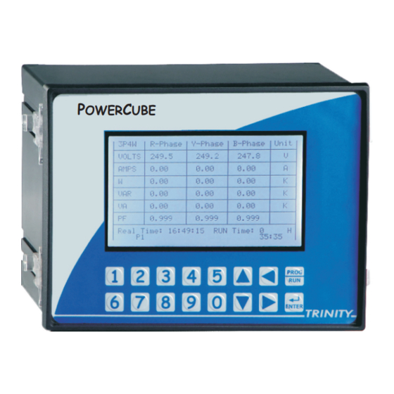
Page 33: Run Mode In 3P4W
PowerCube – Operational Manual 3.2.1 Run mode in 3P4W First page shows phase wise individual parameters as under: 3P4W R-Phase Y-Phase B-Phase Unit VOLTS 220.5 224.7 219.2 AMPS 70.3 72.6 71.4 13.59 14.35 13.72 7.49 7.75 7.52 15.52 16.31 15.65 0.875... - Page 34 09/10/2006 12:48:30 KVAR 09/10/2006 14:14:05 0.568 09/10/2006 12:17:20 8.24 09/10/2006 12:48:29 Real Time: 08:51:43 [Minimum] This fourth page shows system minimum values as recorded since last reset. PowerCube will not sense minimum values for 5 seconds after power on. TRINITY...
- Page 35 PowerCube – Operational Manual Avg. 09/10/2006 12:18:19 Avg. 1410 09/10/2006 12:16:31 09/10/2006 12:17:23 09/10/2006 12:48:30 KVAR 09/10/2006 14:14:05 0.568 09/10/2006 12:17:20 8.24 09/10/2006 12:48:29 Real Time: 08:51:43 [Maximum] This fifth page shows the maximum values of Average Volts, Average Amps, KW, KVA, KVAR, PF &...
- Page 36 PowerCube – Operational Manual ODD Harmonics Histogram I r [ % ] THD=3.1% The seventh page shows ODD Harmonic Histogram for R-Phase current (Ir) in percentage form. ODD Harmonics Histogram Vyn [%] THD=3.7% The eighth page shows ODD Harmonic Histogram for Y-Phase voltage (Vyn) in percentage form.
- Page 37 PowerCube – Operational Manual ODD Harmonics Histogram IY [%] THD=3.5% The ninth page shows ODD Harmonic Histogram for Y-Phase current (Iy) in percentage form. ODD Harmonics Histogram Vbn [%] THD=3.4% The tenth page shows ODD Harmonic Histogram for B-Phase voltage (Vbn) in percentage form.
- Page 38 PowerCube – Operational Manual ODD Harmonics Histogram Ib [%] THD=4.2% The eleventh page shows ODD Harmonic Histogram for B-Phase current (Ib) in percentage form. Waveform - Vrn 0.00 V 50.00 3.52% Vr = 0.00 Vy = 118.19 Vb = 238.96 Twelfth Page shows Voltage waveforms.
- Page 39 PowerCube – Operational Manual R-Phase Harmonics - Volts [%] Value Value Value Real Time: 08:51:43 RUN Time : 0 32:13 Pages 18th to 23rd indicate odd harmonics values for all voltages and currents in text format. TYPES LOGS OVERFLOW System...
- Page 40 PowerCube – Operational Manual Next lines show the number of events with respect to defined event parameters, and their respective overflow status. Each of the four events can have forty event occurrences which are stored with their time of occurrence. After the 40 occurrence, the oldest occurrence will get replaced with a new one, and the overflow flag will indicate this.
- Page 41 PowerCube – Operational Manual PARA SET-V SYS-V TR / TS RL /S 100 / 95 21 / 30 100 / 105 10 / 10 100 / 102 / 20 NONE ----- 100 / 98 3 / 3 0.94 / 0.99 0.98...
- Page 42 PowerCube – Operational Manual 3P4W-SYSTEM VECTOR PF – r = 0.979 PF – Y = 0.988 PF – B = 0.977 Vr = 0.00 Vy = 121.20 Vb = 238.69 Twenty eighth page shows the vector diagram for all the voltages and currents.
-
Page 43: Run Mode In 3P3W
PowerCube – Operational Manual 3.2.2 Run Mode in 3P3W 3P3W R-Phase Y-Phase B-Phase Unit VOLTS 220.5 - , -- 219.2 AMPS 70.3 - , -- 71.4 13.59 - , -- 13.72 7.49 - , -- 7.52 Real Time: 08:51:43 RUN Time : 0... -
Page 44: Communication
RS232 communication options is also available in PowerCube. These options make it possible for a user to select PowerCube to provide power and energy information into a variety of existing or new control systems and communication networks. Each communication option supports data transfer with external devices or applications. -
Page 45: Data Logging And Rs232C
PowerCube – Operational Manual 4.2 Data Logging and RS232C PowerCube has an 2 MB of non-volatile memory. This memory is used to store the minimum and maximum values of important parameters, user defined events and the snapshot of the entire electrical system where all instantaneous and integrated parameters along with Harmonic data are saved. -
Page 46: Installing The Rs232 Software
PowerCube – Operational Manual 4.2.1 Installing the RS232 logger Setup software 1. Insert the CD into the CD-ROM drive after window is starting. 2. Double-click the Logger that contains a list of folder. 3. Select Logger Setup to give a list of folder with setup. - Page 47 PowerCube – Operational Manual Choose the desired directory in the Directory list. Simultaneously, Path and Directories lists will also change when selected. click OK to return to the Previous Directory dialog box. Or, to cancel the new setting, click Cancel and return to the previous Directory dialog box.
-
Page 48: Logger Window Utility
PowerCube – Operational Manual Click Continue to continue and display a Version Conflict dialog box that asks you to keep your existed file. Click Yes to keep the existed file and except the new Version Numbers. It will give you second Version Conflict dialog box after changing the default version numbers. -
Page 49: Handling The Rs232 Logger
PowerCube – Operational Manual Handling the RS232 Logger 4.3.1 Setting COM number and Baud rate Before retrieving the data from your unit, ensure that the cable (9-Pin D- Connector cable) is connected in between the unit and PC with power supply, and then adjust the COM number and Baud rate. -
Page 50: Setting Kwh Consumption For Any Particular Time
PowerCube – Operational Manual 4. Click button at the bottom of the right corner of logger window to export the logged data and save to any location and then, take print out also. 4.3.3 Selecting KWh consumption for any particular time The Logger utility enables to calculate KWh consumption from the logged beginning to till date. -
Page 51: Setting A Printer To Export The Data
PowerCube – Operational Manual 3. In time box, enter the time and in Date box, enter date and then select the types of power sources such as EB and DG. Now, click Export to export the logged KWh for the time period entered in the dialog box and save into excel file. -
Page 52: Exporting The System Data
PowerCube – Operational Manual 3. Click button at the bottom of the right corner to export the Event in excel sheet. 4. Or, click button at the top of the right corner to close the Event window. 4.3.7 Exporting the System Data 1. -
Page 53: Exporting Odd Harmonics Data
PowerCube – Operational Manual 4. Select the file location and enter file name in the File Name box and then click Save to save as excel sheet. The excel will open as before logger system data. 5. Or click Cancel to cancel the exporting system data. -
Page 54: Setting A Histogram
PowerCube – Operational Manual 4.3.9 Setting a Histogram for harmonic graph representation 1. Select Histogram on the harmonic data window, (if not selected by defaults), click on any particular date and time of the harmonic data window to represent the data into Histogram such as shown below: 2. -
Page 55: Setting A Trending Graph
PowerCube – Operational Manual 4.3.10 Setting a Trending graph 1. On the previous Harmonic Data window, select Trending, select phase type in the Phase list, select Date in the Date list and select odd harmonic in the Odd Harmonic check box according to your requirement, and then click Plot to represent the odd harmonic data such as shown the following. -
Page 56: Displaying A Graph
PowerCube – Operational Manual 3. Select Hour option and in the first and second Hour list, select Hour and then click Ok to show for a Harmonic Trending with particular time in hour. 4. Or, select Minute option and in the first and second Minute list, select Minute and then in the Hour list, select Hour. - Page 57 PowerCube – Operational Manual 3. Now, in the Color box, click any of the following harmonic to change the color representation and receive the following such color box. 4. To select any color, click on any of the Color box, or to select Custom color, click Define Custom Colors, and then click on which to select the desired color code.
-
Page 58: Control Outputs
The relay outputs in PowerCube are in electromechanical form with contacts rated at 3A at 250V ac. There are twelve relays in PowerCube which are more than just relay outputs. These relays can be used for Alarm/Trip function or for PF correction operation. - Page 59 PowerCube – Operational Manual The status of each of the relays can be seen in Run Mode as under: PARA SET-V SYS-V TR / TS RL / S 100 / 95 21 / 30 100 / 105 10 / 10...
-
Page 60: Demand Management With Alarm Mode
In case of sliding window, automatic synchronization with the EB meter is guaranteed. In case the fixed window is selected, then, the onus of ensuring that PowerCube's real time clock matches that of the EB meter is on the users. -
Page 61: Pf Correction
It is designed to provide accurate and reliable control of Power Factor in an electrical installation. In case user wants to use the twelve relay outputs for PF correction, PowerCube has to be programmed as shown below:... - Page 62 PowerCube – Operational Manual BINARY In BINARY mode, the unit switches on/off the banks in binary bit pattern i.e. for three banks; it will be as table below: Bank 3 Bank 2 Bank 1 This pattern is useful when each successive bank is twice the size of the previous bank, and the no.
- Page 63 # 27 Switching Delay : - After every switching of the capacitors for PF control (whether ON or OFF), PowerCube stops taking control action for Switching Delay (SW Delay) number of seconds. This is one type of a digital dead band.
- Page 64 PowerCube – Operational Manual The status of the PF correction functioning can be seen in Run mode page No. 25 as under: PF - Controlling VAR / 12 Set - PF 0.999 Set - PF 0.980 SW Delay 3 [03]...
-
Page 65: Address Map For Rs485 For The Various Parameters Installation In 3P4W And 3P3W
PowerCube – Operational Manual Appendix A Address map for RS 485 for the various parameters Installation of 3P4W & 3P3W: (In case of 3P3W, Users are advised to use only the highlighted parameters) Installation – 3P4W & 3P3W Parameter Address... - Page 66 PowerCube – Operational Manual PowerCube – Operational Manual Appendix A Parameter Address MF Factor 40274 Address map for RS 485 for the various parameters Installation of 3P4W & 3P3W: KVARh 40276 (In case of 3P3W, Users are advised to use only the highlighted parameters)
- Page 67 PowerCube – Operational Manual Parameter Address MF Factor HVr – THD 40362 HIr – 3rd 40364 HIr – 5th 40366 HIr – 7th 40368 HIr – 9th 40370 HIr – 11th 40372 HIr – 13th 40374 HIr – 15th 40376 HIr –...
- Page 68 PowerCube – Operational Manual Parameter Address MF Factor HIy – 29th 40450 HIy – THD 40452 HVb – 3rd 40454 HVb – 5th 40456 HVb – 7th 40458 HVb – 9th 40460 HVb – 11th 40462 HVb – 13th 40464 HVb –...
- Page 69 PowerCube – Operational Manual P.O. No. : ………………………………………………………………… Customer : ………………………………………………………………… Sr. No. : ………………………………………………………………… Routine and function tests conducted to relevant standards and our Specifications/Literature/O & M Manual. Traceability: tested against "MTE" Standard Model PRS1.3 having basic accuracy of 0.05% traceable upto International Standards derived using appropriate ratio techniques.
- Page 70 TRINITY ENERGY SYSTEMS PVT. LTD. 366/A/12, G.I.D.C. Estate, Makarpura, VADODARA-390010, Gujarat, India Tele/ Fax. : 0265 - 2645738/ 2633270/ 2632761 email : info@trinityenergy.co.in web : www.trinityenergy.co.in...
Need help?
Do you have a question about the POWERCUBE and is the answer not in the manual?
Questions and answers