Table of Contents
Advertisement
Quick Links
Advertisement
Table of Contents
Troubleshooting

Subscribe to Our Youtube Channel
Related Manuals for KEHUA TECH MR33 Series


Summary of Contents for KEHUA TECH MR33 Series
- Page 1 MR33 Series (300K-800K) Modular UPS User Manual...
- Page 3 Copyright © Kehua Hengsheng Co., Ltd. 2020.All rights reserved. No part of this document may be reproduced or transmitted in any form or by any means without prior written consent of Kehua Hengsheng Co., Ltd. Trademarks and Permissions and other Kehua trademarks are trademarks of Kehua Hengsheng Co., Ltd. All other trademarks and trade names mentioned in this document are the property of their respective holders.
- Page 4 MR33 Series (300K-800K) Modular UPS Foreword User Manual Foreword Summaries Thank you for choosing the modular MR series modular UPS! This document gives a description of the MR series modular UPS, including the features, performance, appearance, structure, working principles, installation, operation and maintenance etc.
- Page 5 MR33 Series (300K-800K) Modular UPS User Manual Foreword Symbol Description Anti-static prompting. Be care electric shock prompting. Provides a tip that may help you solve a problem or save time. Provides additional information to emphasize or supplement important points in the main text.
-
Page 6: Table Of Contents
MR33 Series (300K-800K) Modular UPS Contents User Manual Contents 1 Safety Description......................... 1 1.1 Safety Announcements ............................. 1 1.1.1 Safety Instructions ..........................1 1.1.2 Use Announcements for Battery ......................4 1.1.3 Anti-Static Protection ..........................5 1.1.4 Grounding Requirements ........................5 1.1.5 Safety Warning Label Setting ......................... - Page 7 MR33 Series (300K-800K) Modular UPS User Manual Contents 2.6.4 Synchronous BSC ..........................27 2.6.5 Battery temperature compensation ......................27 2.6.6 Lightning protection facilities ....................... 28 2.7 Alarm Function ............................... 28 3 Installation............................ 39 3.1 Installation Procedure ............................. 39 3.2 Installation Preparation ..........................40 3.2.1 Installation Tools ...........................
- Page 8 MR33 Series (300K-800K) Modular UPS Contents User Manual 3.8.3 Connect Load ............................67 4 Touch Screen Operation and Setting ..................68 4.1 Menu Structure ............................... 68 4.2 Main Page ..............................69 4.3 System Work Status Display .......................... 70 4.4 Buzzer Control Function ..........................75 4.5 Monitor Function ............................
- Page 9 MR33 Series (300K-800K) Modular UPS User Manual Contents 5.4 Parallel System Startup and Shutdown......................90 5.4.1 Start Parallel System ..........................90 5.4.2 Shutdown Parallel System ........................93 5.4.3 Emergency Power Off (EPO) ........................ 94 6 Maintenance and Troubleshooting ..................95 6.1 Maintenance Guide ............................
-
Page 11: Safety Description
MR33 Series (300K-800K) Modular UPS User Manual 1 Safety Description 1 Safety Description This chapter introduces the safety announcements. Prior to performing any work on the UPS, please read the user manual carefully to avoid human injury and device damage by irregular operations. - Page 12 MR33 Series (300K-800K) Modular UPS 1 Safety Description User Manual It is prohibited to touching any terminal or conductor that connected with grid circuit, or, it may cause deadly danger. The damaged device or device fault may cause electric shock or firing! ⚫...
- Page 13 MR33 Series (300K-800K) Modular UPS User Manual 1 Safety Description If the output of the UPS cannot be half-wave rectification load or inductive load, such as air-condition, hair drier, starter, electric drill, motor, daylight lamp, etc. Please do not put finger or tool into rotating fans to avoid endanger the human safety or damage the device.
-
Page 14: Use Announcements For Battery
MR33 Series (300K-800K) Modular UPS 1 Safety Description User Manual Warning label should be affixed away from UPS location! When UPS is power off, there still exists dangerous voltage. It should affix warning labels away from UPS location and the warning labels should include: 1. It supplies power for UPS. 2. Please disconnect UPS before wiring. -
Page 15: Anti-Static Protection
MR33 Series (300K-800K) Modular UPS User Manual 1 Safety Description 1.1.3 Anti-Static Protection The static generated by human bodies may damage the electrostatic-sensitive components on PCB. Before touching the sensitive component, please wear anti-static rings and well connect the other end of the anti-static rings to ground. - Page 16 MR33 Series (300K-800K) Modular UPS 1 Safety Description User Manual supplement to the local safety regulations. Our company does not undertake the responsibility caused by violating the common safety operation requirements or safety standards for design, manufacture and use the device.
-
Page 17: Environment Requirements
MR33 Series (300K-800K) Modular UPS User Manual 1 Safety Description Drilling holes on the cabinet is prohibited! Inappropriate drilling will damage the components inside the UPS. Metal debris generated by drilling will lead to circuit board short circuit. Changing the UPS configuration, structure or assembly will affect the performance of the UPS. If user needs to do like this, please consult the manufacturer in advance. -
Page 18: Overview
MR33 Series (300K-800K) Modular UPS 2 Overview User Manual 2 Overview This chapter mainly introduces the product features, work principle, structure of the UPS, including panel indicator meaning and signal port illustration. 2.1 Product Intro MR series UPS is modular online double-conversion UPS. They are made up of cabinet, power module, bypass module, system control box and distribution unit. - Page 19 MR33 Series (300K-800K) Modular UPS User Manual 2 Overview Energy conservation and high efficiency Adopts advanced PFC control technology, the input power factor is greater than 0.99, which greatly improves the use ratio of electric energy and reduces the load of power grid, and save the cost of power distribution.
-
Page 20: Work Principle
MR33 Series (300K-800K) Modular UPS 2 Overview User Manual 2.3 Work Principle 2.3.1 Work Principle Diagram Work principle diagram of the UPS is as shown in Figure2-1. Maintenance bypass Bypass input Bypass module Mains input Output Battery input Power module 1... - Page 21 MR33 Series (300K-800K) Modular UPS User Manual 2 Overview Battery power supply mode When mains abnormal, system will switch to battery input, the Boost circuit promotes the battery voltage to a certain value and then supply the DC power to the inverter, that makes the AC output without interruption phenomenon and then protect the load.
-
Page 22: Structure
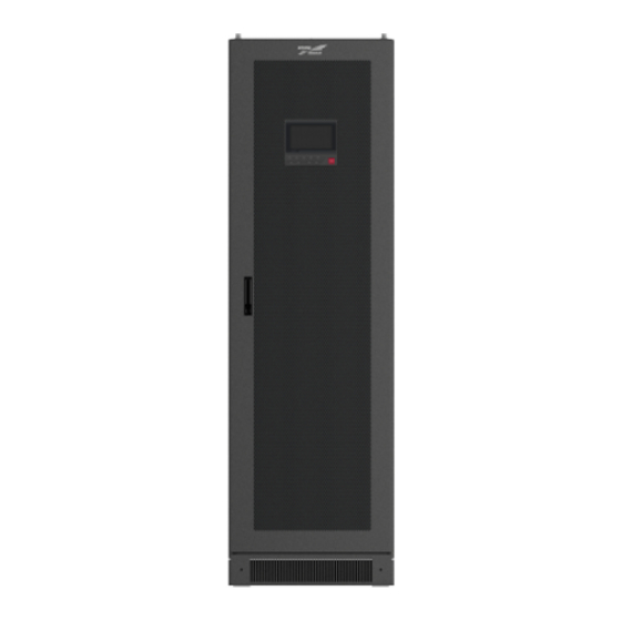
MR33 Series (300K-800K) Modular UPS 2 Overview User Manual transforming of manual maintenance bypass, AC power is supplied for load by maintenance bypass breaker. At this time, the inner UPS has no electricity, maintainer can perform the maintenance safely. 2.4 Structure MR series modular UPS is mainly made up of cabinet, operation panel, power module, bypass module, system control box, distribution plate, etc. - Page 23 MR33 Series (300K-800K) Modular UPS User Manual 2 Overview Figure2-3 Appearance of MR33400, MR33500, MR33600 Figure2-4 Appearance of MR33800 All rights reserved ©Kehua Hengsheng Co., Ltd.
- Page 24 MR33 Series (300K-800K) Modular UPS 2 Overview User Manual Operation Panel Figure2-5 Operation panel of MR series modular UPS Table2-1 Illustration for the operation panel Name Illustration ○ Touch screen Human-machine interactive interface On (green): the rectifier work normally. ○...
-
Page 25: Sturcture Layout
MR33 Series (300K-800K) Modular UPS User Manual 2 Overview 2.4.1 Sturcture Layout The system layout diagram takes the power module full allocation as an example, please refer to the real product. MR33300 Figure2-6 System layout diagram of MR33300 (top wiring) - Page 26 MR33 Series (300K-800K) Modular UPS 2 Overview User Manual MR33400, MR33500, MR33600 Figure2-7 System layout diagram of MR33400, MR33500, MR33600 MR33800 Figure2-8 System layout diagram of MR33800 All rights reserved ©Kehua Hengsheng Co., Ltd.
-
Page 27: Assembly Unit Illustration
MR33 Series (300K-800K) Modular UPS User Manual 2 Overview 2.5 Assembly unit illustration 2.5.1 Power Module/Bypass Module Power module has the similar appearance as the bypass module. The different point is only the label above the right indicator light. Power module label is PM. Bypass module label is BM. -
Page 28: System Control Box
MR33 Series (300K-800K) Modular UPS 2 Overview User Manual Name Illustration the power module is locked with the cabinet, and at this time, the power unit cannot be dismantled. 2.5.2 System Control Box The system control box unit is as shown inFigure2-10. - Page 29 MR33 Series (300K-800K) Modular UPS User Manual 2 Overview Name Illustration secondary card. ○ FAULT indicator (red) On: system control card fault System monitor card There is a human-machine interactive communication port, 3 input dry contact communication signal and 3 output dry contact signal (as shown in Figure2-12), specific definition is as shown in Table2-4.
- Page 30 MR33 Series (300K-800K) Modular UPS 2 Overview User Manual Port Name Illustration cannot be set. COM Reinforced insulation ground External EPO normally close interface When the NO and EPO disconnect, the signal is effective. The signal is a preset completion...
- Page 31 MR33 Series (300K-800K) Modular UPS User Manual 2 Overview Port Name Illustration set for the content. COM Reinforced insulation ground The four input ports on the system monitor card can be defined (as shown in the Table2-5) according to user requirements.
-
Page 32: Optional Accessories
MR33 Series (300K-800K) Modular UPS 2 Overview User Manual Definition Remark Battery under-voltage Battery discharge to under-voltage protection state, this dry ○ protection contact in ON state. ○ Output overload UPS in the overload state, this dry contact in ON state. - Page 33 MR33 Series (300K-800K) Modular UPS User Manual 2 Overview E indicator (red) Illustration C indicator (yellow) R indicator (green) Slow flash Slow flash UPS is running UPS is making over time Long bright Slow flash judgments Long bright Slow flash UPS is disconnected.
- Page 34 MR33 Series (300K-800K) Modular UPS 2 Overview User Manual Please ensure that the setting IP address is in the same network segment with user's computer IP address. After the SNMP installation and its cables connection are all complete, please configure the software in the following order.
-
Page 35: Expansion Cards
MR33 Series (300K-800K) Modular UPS User Manual 2 Overview 2.6.2 Expansion cards Dry contact expansion card The dry contact extension card (as shown in Figure2-15) is mainly used for the collection of detection of detection signals. Dry contact card includes three input dry contact communication signals and two output dry contact signals. - Page 36 MR33 Series (300K-800K) Modular UPS 2 Overview User Manual Port Name Illustration set for the content. COM Reinforced insulation ground External switch normally open input When the NO and COM short circuit, interface IN.7 the signal is effective. This single can be set for the content.
-
Page 37: Parallel System Connection
MR33 Series (300K-800K) Modular UPS User Manual 2 Overview Port Name Illustration External switch normally open input When the NO and COM short circuit, interface IN.9 the signal is effective. COM Reinforced insulation ground 2.6.3 Parallel System Connection ⚫ Parallel of two UPS Figure2-17 Parallel system (with 2 UPS) connection ⚫... -
Page 38: Lightning Protection Facilities
MR33 Series (300K-800K) Modular UPS 2 Overview User Manual When the battery temperature compensation function is selected, it will be randomly configured that one temperature control wire, one temperature control extension cord and one 2Pin green terminal. Figure2-19 Battery temperature compensation connection diagrammatic drawing The temperature control wire should be fixed in the higher temperature area of the battery area. - Page 39 MR33 Series (300K-800K) Modular UPS User Manual 2 Overview fault information Protect require Alarm require Excessive mains harmonic component Mains flash drop Mains overload protection zero wire of mains is missing The DC component of the mains is too large...
- Page 40 MR33 Series (300K-800K) Modular UPS 2 Overview User Manual fault information Protect require Alarm require Bypass flash drop ECO over-voltage ECO output is not ECO under-frequency Buzzer beeps slowly allowed ECO over-frequency ECO under-frequency Inverter output fault Buzzer long beeps, DC/AC...
- Page 41 MR33 Series (300K-800K) Modular UPS User Manual 2 Overview fault information Protect require Alarm require Buzzer long beeps. Bypass Bypass output is not light turns red on the touch Bypass SCR abnormal allowed screen, and bypass icon turns red. Inverter output is not...
- Page 42 MR33 Series (300K-800K) Modular UPS 2 Overview User Manual fault information Protect require Alarm require protection UPS fault None Cabinet pre-alarm None Cabinet over temperature None alarm Battery high temperature None alarm Buzzer beeps apace Battery low temperature None alarm...
- Page 43 MR33 Series (300K-800K) Modular UPS User Manual 2 Overview fault information Protect require Alarm require Buzzer beeps slowly. Bypass installation not Bypass output is not Bypass light turns red on ready allowed touch screen, bypass icon turns red. Setting parameters not...
- Page 44 MR33 Series (300K-800K) Modular UPS 2 Overview User Manual fault information Protect require Alarm require Starting up fault alarm Reserved The load is too large to inverter output Unknown load, waiting common inverter output. PFC software version is not consistent.
- Page 45 MR33 Series (300K-800K) Modular UPS User Manual 2 Overview fault information Protect require Alarm require Bypass fan abnormal Cabinet fan abnormal Parallel wire 1 alarm Parallel wire 2 alarm Bypass 1 installation not ready Bypass 2 installation not ready Monitor card installation...
- Page 46 MR33 Series (300K-800K) Modular UPS 2 Overview User Manual fault information Protect require Alarm require Flow equalization CAN abnormal between cabinets communication abnormal Smart mode alarm Star generator Generator is not allowed to discharge Currently only one BCS system has been detected.
- Page 47 MR33 Series (300K-800K) Modular UPS User Manual 2 Overview fault information Protect require Alarm require contact state Battery abnormal Buzzer beeps apace. BAT light turns red on the touch Battery ground fault screen, and battery icon Battery switch disconnect turns red.
- Page 48 MR33 Series (300K-800K) Modular UPS 2 Overview User Manual fault information Protect require Alarm require Power module 13 offline Power module 14 offline Power module 15 offline Power module 16 offline Power module 17 offline Power module 18 offline Power module 19 offline...
-
Page 49: Installation
MR33 Series (300K-800K) Modular UPS User Manual 3 Installation 3 Installation This chapter mainly introduces the installation of the UPS, including unpacking and checking, installation procedure, installation preparation, mechanical installation and system checking and test, etc. The UPS installation should be performed by authorized person who is special trained and achieve the qualification of high-voltage and AC power. -
Page 50: Installation Preparation
MR33 Series (300K-800K) Modular UPS 3 Installation User Manual 3.2 Installation Preparation 3.2.1 Installation Tools Tools All rights reserved ©Kehua Hengsheng Co., Ltd. -
Page 51: Installation Environment
MR33 Series (300K-800K) Modular UPS User Manual 3 Installation The installation tools should be with isolated operation to avoid electric shock. 3.2.2 Installation Environment ⚫ Do not install the UPS in the place where exceeds the provision of technology index (temperature: 0℃~40℃, relative humidity: 0%~95%). -
Page 52: Installation Space
MR33 Series (300K-800K) Modular UPS 3 Installation User Manual 3.2.3 Installation Space Maintain a clearance of at least 800mm from the front panel, side panel or rear panel of the UPS to the wall or adjacent device, and maintain a clearance of at least 500mm from the top of the UPS to ceiling, which is to ensure good ventilation, as shown in Figure3-2. - Page 53 MR33 Series (300K-800K) Modular UPS User Manual 3 Installation Model MR33300,MR33400,MR33500,MR33600 MR33800 System max. capacity (kVA) 2×(4×120) Recommended 2 × (4 2 × (4 × 3 × (4 × 4 × (4 × 3 × (4 × wire diameter ×185)
-
Page 54: Surge Protection Device
MR33 Series (300K-800K) Modular UPS 3 Installation User Manual Model MR33300,MR33400,MR33500,MR33600 MR33800 System max. capacity (kVA) Recommended wire 2×185 3×185 diameter (mm Wire terminal model DT-120 DT-185 DT-185 DT-185 DT-185 The wires prepared by our company have passed the GB or UL certification. The wires quality is excellent, and all meet the production compliance. -
Page 55: Unpacking
MR33 Series (300K-800K) Modular UPS User Manual 3 Installation Figure3-3 Motor-driven forklift Figure3-4 Manual forklift When lifting, pay attention to the balance and stable of the UPS. During moving, keep the UPS vertical and do not put down or uplift suddenly. - Page 56 MR33 Series (300K-800K) Modular UPS 3 Installation User Manual Step 3 Unpack the external package. Remove the foam pad and plastic bag, and take out the accessories and built-in documents. Step 4 Check the UPS. ⚫ Inspect the appearance of the UPS and check if there has any damage caused by transportation. If any damage, please inform the carrier immediately.
-
Page 57: Mechanical Installation
MR33 Series (300K-800K) Modular UPS User Manual 3 Installation 3.4 Mechanical Installation If the UPS is installed on the ground, it is necessary to set the wire groove to connect wires in advance, details as follows. In this section, we take ground installation as an example to illustrate. - Page 58 MR33 Series (300K-800K) Modular UPS 3 Installation User Manual Figure3-8 Size of MR33300 Figure3-9 Size of MR33400, MR33500, MR33600 All rights reserved ©Kehua Hengsheng Co., Ltd.
- Page 59 MR33 Series (300K-800K) Modular UPS User Manual 3 Installation Figure3-10 Size of MR33800 Step 2 Drill 4 holes (hole diameter isφ13) by hammer drill according to the bottom installation hole size (as shown in Figure3-11, Figure3-12, Figure3-13). If the UPS is installed on U-steel, drill 4 hole (hole diameter isφ14) on the U-steel directly, and then perform Step 4 directly.
- Page 60 MR33 Series (300K-800K) Modular UPS 3 Installation User Manual Figure3-12 Bottom size of MR33400, MR33500, MR33600 (unit: mm) Figure3-13 Bottom size of MR33800 (unit: mm) Step 3 Install expansion bolts. The structure and installation for the expansion bolt is as shown in Figure3-14.
- Page 61 MR33 Series (300K-800K) Modular UPS User Manual 3 Installation Take whole expansion tube into the hole as standard of expansion bolt installation depth. Expansion tube should not higher than ground, which is to avoid effect the following cabinet installation. The outer height of expansion bolts should be within the range of 30-50mm.
-
Page 62: Install Optional Accessory
MR33 Series (300K-800K) Modular UPS 3 Installation User Manual Install bottom cover plates of MR33300, MR33400, MR33500, MR33600 and MR33800 are some, here we take the MR33300, MR33400 as the example to illustrate. ----End 3.5 Install optional accessory 3.5.1 SNMP card SNMP card (optional) is shipped separately, which requires field installation. -
Page 63: System Wiring
MR33 Series (300K-800K) Modular UPS User Manual 3 Installation Step 1 Loosen the screw of the dry contact expansion card sealing plate on the control unit, and remove the king contact expansion card sealing plate, as shown in Figure3-18. Figure3-18 Remove the dry contact expansion card plate Step 2 Install the dry contact expansion card, as shown in Figure3-19. - Page 64 MR33 Series (300K-800K) Modular UPS 3 Installation User Manual Figure3-20 Remove the sealing plate schematic diagram Step 2 Connect the input, output and battery wires according to Figure3-21, and fasten the bolts. Figure3-21 Inlet and outlet schematic diagram All rights reserved ©Kehua Hengsheng Co., Ltd.
- Page 65 MR33 Series (300K-800K) Modular UPS User Manual 3 Installation Figure3-22 Copper bar position of MR33300 Figure3-23 Copper bar position of MR33300 When the mains and bypass are in the same power supply mode, the UPS should connect the optional copper, as shown in Figure3-24.
- Page 66 MR33 Series (300K-800K) Modular UPS 3 Installation User Manual Figure3-24 Install optional copper bar It needs to equip DC breaker for battery DC input, specific wire connection is as shown in Figure3-25. Figure3-25 Battery wire connection diagram Step 3 After finishing the wire connection, install the top cover, and then the wiring is completed.
-
Page 67: Mr33400, Mr33500, Mr33600
MR33 Series (300K-800K) Modular UPS User Manual 3 Installation ----End 3.6.2 MR33400, MR33500, MR33600 Step 1 Open the front door of distribution cabinet, place the input switch, output switch, maintenance switch, bypass switch to OFF, as shown in Figure3-26. Figure3-26 Place the switch to OFF... - Page 68 MR33 Series (300K-800K) Modular UPS 3 Installation User Manual Figure3-28 Wiring terminal of distribution cabinet ⚫ If the wiring is from upside, it needs to make the cable go through the top styrofoam, and then connect the cables. ⚫ If the wiring is form downside, it needs to knock down the bottom wiring hole, and then connect the cables.
- Page 69 MR33 Series (300K-800K) Modular UPS User Manual 3 Installation Figure3-29 Battery wire connection diagram When wiring, ensure that the input, output wires and input, output terminal contact firmly and must not contact bad or wrong. Step 4 After wiring, fasten the cables to corresponding epoxy plate by cable tie (as shown in Figure3-30, Figure3-31), and install the wiring cover plate again, and then install the handle of switch.
- Page 70 MR33 Series (300K-800K) Modular UPS 3 Installation User Manual Figure3-30 Wiring diagram of distribution cabinet (top wiring) Figure3-31 Wiring diagram of distribution cabinet (bottom wiring) All rights reserved ©Kehua Hengsheng Co., Ltd.
-
Page 71: Mr33800
MR33 Series (300K-800K) Modular UPS User Manual 3 Installation Step 5 After confirming the correct wiring, reinstall the UPS front and rear sealing plate according to the original position, and the wiring is completed. ----End After finish the assembling, perform the test and then the UPS can be put in use. - Page 72 MR33 Series (300K-800K) Modular UPS 3 Installation User Manual Figure3-33 Dismantle the wiring cover plate of distribution cabinet Step 3 Connect the input, output and battery wires according to Figure3-34 in proper order, and then fasten the bolts. All rights reserved ©Kehua Hengsheng Co., Ltd.
- Page 73 MR33 Series (300K-800K) Modular UPS User Manual 3 Installation Figure3-34 Wiring terminal of distribution cabinet ⚫ If the wiring is from upside, it needs to make the cable go through the top styrofoam, and then connect the cables. ⚫ If the wiring is form downside, it needs to knock down the bottom wiring hole, and then connect the cables.
- Page 74 MR33 Series (300K-800K) Modular UPS 3 Installation User Manual Figure3-35 Battery wire connection diagram When wiring, ensure that the input, output wires and input, output terminal contact firmly and must not contact bad or wrong. Step 4 After wiring, fasten the cables to corresponding epoxy plate by cable tie and install the wiring cover plate again, and then install the handle of switch.
-
Page 75: Parallel System Connection
MR33 Series (300K-800K) Modular UPS User Manual 3 Installation 3.7 Parallel System Connection 3.7.1 Parallel system connection of MR33300 Figure3-36 Parallel system connection diagram of MR33300 (top wiring) The wire color above is just used to distinguish the different ports, the actual wire color may not be the same as shown in the figure’s. -
Page 76: System Check And Test
MR33 Series (300K-800K) Modular UPS 3 Installation User Manual Figure3-38 Parallel system connection diagram of MR33400,MR33500,MR33600,MR33800 (bottom wiring) The wire color above is just used to distinguish the different ports, the actual wire color may not be the same as shown in the figure’s. -
Page 77: Ups Test
MR33 Series (300K-800K) Modular UPS User Manual 3 Installation Check item Result complete. Yes□ No□ Check if the wire connection point is firmly. Yes□ No□ Check if the battery is connected in right polarity and sequence. Yes□ No□ Check if the cable identification is correct. -
Page 78: Touch Screen Operation And Setting
MR33 Series (300K-800K) Modular UPS 4 Touch Screen Operation and Setting User Manual 4 Touch Screen Operation and Setting This chapter mainly introduces the work parameters and work status and system setting of the UPS. 4.1 Menu Structure Mains input... -
Page 79: Main Page
MR33 Series (300K-800K) Modular UPS User Manual 4 Touch Screen Operation and Setting The value in the figures of this chapter is just for illustration, for real page please see the actual achieved product. 4.2 Main Page After powering on, it will enter system monitor main page, as shown in Figure4-2. -
Page 80: System Work Status Display
MR33 Series (300K-800K) Modular UPS 4 Touch Screen Operation and Setting User Manual : Information record. : System parameter setting. : Login. : Buzzer control. : Alarm. : ON/OFF. The work status and energy flow on the main page shows the system running status and module running condition directly. - Page 81 MR33 Series (300K-800K) Modular UPS User Manual 4 Touch Screen Operation and Setting Figure4-4 Shutdown Figure4-5 Bypass output All rights reserved ©Kehua Hengsheng Co., Ltd.
- Page 82 MR33 Series (300K-800K) Modular UPS 4 Touch Screen Operation and Setting User Manual Figure4-6 Battery INV. output Figure4-7 Mains INV. output All rights reserved ©Kehua Hengsheng Co., Ltd.
- Page 83 MR33 Series (300K-800K) Modular UPS User Manual 4 Touch Screen Operation and Setting Figure4-8 Grid-connected aging running Figure4-9 ECO bypass output All rights reserved ©Kehua Hengsheng Co., Ltd.
- Page 84 MR33 Series (300K-800K) Modular UPS 4 Touch Screen Operation and Setting User Manual Figure4-10 Frequency conversion INV. output Figure4-11 Maintenance bypass output When module or system abnormal, the main page will show “fault alarm” indicator, click the “fault alarm”, it will show the current fault information, as shown in Figure4-12.
-
Page 85: Buzzer Control Function
MR33 Series (300K-800K) Modular UPS User Manual 4 Touch Screen Operation and Setting Figure4-12 Current fault information page 4.4 Buzzer Control Function When module or system abnormal, the system will send sound alarm. User can click the icon at left to close or open the buzzer. After closed, if there is new fault, the buzzer will be opened automatically. -
Page 86: Mains Information
MR33 Series (300K-800K) Modular UPS 4 Touch Screen Operation and Setting User Manual Figure4-13 Bypass information 4.5.2 Mains Information In main page, click icon, it will enter system mains input information page, as shown in Figure4-14. In the page, it shows the mains three-phase voltage, current, frequency and total input energy of current system. -
Page 87: Battery Information
MR33 Series (300K-800K) Modular UPS User Manual 4 Touch Screen Operation and Setting 4.5.3 Battery Information In main page, click icon, it will enter battery information page. If the battery is lead-acid cell, it shows the positive and negative battery group voltage, charge/discharge current, remaining capacity, battery remaining time, battery temperature, battery status. -
Page 88: Inverter Information
MR33 Series (300K-800K) Modular UPS 4 Touch Screen Operation and Setting User Manual Figure4-16 Rectifier information 4.5.5 Inverter Information In main page, click icon, it will enter inverter module information page, as shown in Figure4-17. Click “Select Module”, it can check the information of each power module. -
Page 89: Output Information
MR33 Series (300K-800K) Modular UPS User Manual 4 Touch Screen Operation and Setting 4.5.6 Output Information In main page, click icon, it will enter system output information page, as shown in Figure4-18. In the page, it shows the current three-phase output voltage, current, active power, apparent power, load percentage, frequency and total output energy. -
Page 90: Event Log
MR33 Series (300K-800K) Modular UPS 4 Touch Screen Operation and Setting User Manual It can record 10000 pieces information at most. When the record exceeds 10000 piece, the earliest information will be covered by new one. All records are ranked in inverted order of time. -
Page 91: Device Information
MR33 Series (300K-800K) Modular UPS User Manual 4 Touch Screen Operation and Setting Figure4-21 User log 4.6.3 Device Information In information query page, click Device Info icon, it will enter device information page. This page shows the S/N, product name, model, status, version, as shown in Figure4-22, Figure4-23, Figure4-24. -
Page 92: On/Off
MR33 Series (300K-800K) Modular UPS 4 Touch Screen Operation and Setting User Manual Figure4-23 Product information 2 Figure4-24 Product information 3 4.7 ON/OFF In main page, click icon, it will enter ON/OFF page, when the system is OFF, click the icon to enter the confirm page, as shown in Figure4-25, click OK button to perform the start operation. - Page 93 MR33 Series (300K-800K) Modular UPS User Manual 4 Touch Screen Operation and Setting Figure4-25 Confirm to power on All rights reserved ©Kehua Hengsheng Co., Ltd.
-
Page 94: Use And Operation
MR33 Series (300K-800K) Modular UPS 5 Use and Operation User Manual 5 Use and Operation This chapter mainly introduces the operation procedure and method, including using announcements, operation procedure, UPS start and parallel system start, etc. 5.1 Use Announcements ⚫ Before starting the UPS, check whether the load is proper. The load must not exceed the rated output power of the UPS, which is to avoid overload protection. -
Page 95: Ups Start And Shutdown
MR33 Series (300K-800K) Modular UPS User Manual 5 Use and Operation 5.3 UPS Start and Shutdown 5.3.1 Check before Startup Before startup, check according to following steps. Only when the check is OK, then the UPS can be started. Step 1 Ensure that the POWER switch, BYPASS switch, OUTPUT switch, MAINTENANCE switch are all OFF. - Page 96 MR33 Series (300K-800K) Modular UPS 5 Use and Operation User Manual ⚫ Start the inverter method 1: Panel ON combination button When the green indicator of all power module slow flicker, long press the panel “ON” combination button for 3s, the system will inverters to output. Check the system running status in the touch screen, and ensure that the system turns to inverter power supply mode.
-
Page 97: Ups Shutdown
MR33 Series (300K-800K) Modular UPS User Manual 5 Use and Operation 5.3.3 UPS Shutdown If the system bypass normal, after the UPS shutdown, system will turn to bypass power supply mode; if system bypass abnormal, after the UPS shutdown, system will be with no output. Before shutting down, please ensure that the load is closed. -
Page 98: Switch To Bypass Mode Manually
MR33 Series (300K-800K) Modular UPS 5 Use and Operation User Manual Step 4 After the touch screen and all LED indicators are off, the UPS is completely shut down. ----End 5.3.4 Switch to Bypass Mode Manually Before shutting down the inverter, please ensure that the bypass is normal. If bypass abnormal, after shutting down the inverter manually, the system will be with no output and the power supply for load will be broken off. -
Page 99: Switch To Inverter Power Supply From Maintenance Bypass
MR33 Series (300K-800K) Modular UPS User Manual 5 Use and Operation Step 4 Disconnect OUTPUT switch, after the touch screen, LED indicators are all off, the maintenance can be done. During maintenance, it is strictly forbidden to close the OUTPUT switch. -
Page 100: Emergency Power Off (Epo)
MR33 Series (300K-800K) Modular UPS 5 Use and Operation User Manual 5.3.7 Emergency Power Off (EPO) Do not perform the EPO operation unless emergency. Press the EPO button on the panel or external EPO button of system, the UPS will turn to emergency power off status. - Page 101 MR33 Series (300K-800K) Modular UPS User Manual 5 Use and Operation 1. Before start the parallel system, please perform the operation of 5.3 UPS Start and Shutdown for each UPS. 2. Before test and power on the parallel system, please ensure that the wire connection of input and output cables and phase sequence is right and the parallel wire is well connected and stay in disconnection status.
- Page 102 MR33 Series (300K-800K) Modular UPS 5 Use and Operation User Manual real-time data in touch screen, measure the front-end three-phase output voltage of output breaker in output distribution cabinet or external output distribution breaker, ensure that the inverter output voltage is normal (the three-phase output voltage = output voltage setting ±2V), and ensure that the inverter frequency is normal (the three-phase output frequency = output frequency setting ±0.1Hz).
-
Page 103: Shutdown Parallel System
MR33 Series (300K-800K) Modular UPS User Manual 5 Use and Operation Ensure that each UPS with no abnormal alarm, shut down the inverter of all UPS, the system turns to bypass power supply. Step 14 Close the total output breaker of load. -
Page 104: Emergency Power Off (Epo)
MR33 Series (300K-800K) Modular UPS 5 Use and Operation User Manual 5.4.3 Emergency Power Off (EPO) Single UPS running Press the EPO button of the UPS or the EPO button of total system, the UPS will shut down and close all output. -
Page 105: Maintenance And Troubleshooting
MR33 Series (300K-800K) Modular UPS User Manual 6 Maintenance and Troubleshooting 6 Maintenance and Troubleshooting This chapter mainly introduces the UPS maintenance guide, battery daily maintenance, battery replacement announcement and troubleshooting, etc. 6.1 Maintenance Guide Proper maintenance is the key to make the device operate in best status and with a longer service life. -
Page 106: Battery Maintenance
MR33 Series (300K-800K) Modular UPS 6 Maintenance and Troubleshooting User Manual ⚫ Check the UPS status periodically and ensure that any fault can be found in time. 6.2 Battery Maintenance ⚫ Battery charge requirements When first use the battery, please start the UPS and charge the battery for 24h. during −... -
Page 107: Troubleshooting
MR33 Series (300K-800K) Modular UPS User Manual 6 Maintenance and Troubleshooting ⚫ A new battery should be with the same capacity, model, and manufacturer as the replaced one. The battery with different capacity, different type and different manufacturer battery is strictly forbidden to use together. - Page 108 MR33 Series (300K-800K) Modular UPS 6 Maintenance and Troubleshooting User Manual Abnormal phenomena Possible reason 1. The UPS is serious overload or the output circuit is short-circuit. It is necessary to reduce load to proper capacity or find the reason of short-circuit. Common reason is output...
-
Page 109: Emergency Dispose For System Fault
MR33 Series (300K-800K) Modular UPS User Manual 6 Maintenance and Troubleshooting Abnormal phenomena Possible reason Buzzer long beeps, the See the fault information on touch screen. UPS turns to bypass supply power. There mains, The mains voltage or frequency exceed the allowable range of... -
Page 110: Package, Transportation And Storage
MR33 Series (300K-800K) Modular UPS 7 Package, Transportation and Storage User Manual 7 Package, Transportation and Storage This chapter mainly introduces the package, transportation and storage of the UPS. 7.1 Package During packing, please pay attention to the place direction requirements. At the side of the package, there is afraid of wet, handle with care, upward, stack layer limit, etc. -
Page 111: A Technical Specifications
MR33 Series (300K-800K) Modular UPS User Manual A Technical Specifications Technical Specifications Model MR33300 MR33400 MR33500 MR33600 MR33800 Index 3φ4W+PE Input mode Rated input voltage 220/230/240 (phase voltage) (VAC) Vin=187Vac~280Vac, it does not need to decrease rated power to use... - Page 112 MR33 Series (300K-800K) Modular UPS A Technical Specifications User Manual Model MR33300 MR33400 MR33500 MR33600 MR33800 Index 3φ4W+PE Output mode Output wave-form Sine-wave L-N: 220/230/240 Voltage (Vac) L—L: 380/400/415 When mains normal, it tracks the bypass input frequency; Frequency (Hz) When mains abnormal, it tracks the frequency 50±0.1 or 60±0.1 of the...
- Page 113 MR33 Series (300K-800K) Modular UPS User Manual A Technical Specifications Model MR33300 MR33400 MR33500 MR33600 MR33800 Index Inverter overload capacity: ⚫ Linear load(PF=1.0) For less than 105% load, it runs for long-term; For 106%~110% load, it turns to bypass after 60min;...
- Page 114 MR33 Series (300K-800K) Modular UPS A Technical Specifications User Manual Model MR33300 MR33400 MR33500 MR33600 MR33800 Index The load changes in the range of 0%~100% or 100%~0%, the dynamic Dynamic response response transient range of output voltage ≤5% transient range...
- Page 115 MR33 Series (300K-800K) Modular UPS User Manual A Technical Specifications ⚫ Specifications are subject to change without prior notice. All rights reserved ©Kehua Hengsheng Co., Ltd.
-
Page 116: B Physics Characters
MR33 Series (300K-800K) Modular UPS B Physics Characters User Manual Physics Characters Physics Characters Model MR33300 MR33400 MR33500 MR33600 MR33800 Item Supports wiring Wiring way from upside or Supports wiring from upside and downside downside Cabinet without module Power Weight(kg) - Page 117 MR33 Series (300K-800K) Modular UPS User Manual B Physics Characters Model MR33300 MR33400 MR33500 MR33600 MR33800 Item 0%~95% RH (with no condensation) Relative humidity All rights reserved ©Kehua Hengsheng Co., Ltd.
-
Page 118: C Acronyms And Abbreviations
MR33 Series (300K-800K) Modular UPS C Acronyms and Abbreviations User Manual Acronyms and Abbreviations Alternating Current Direct Current Digital Signal Processor Energy Control Operation Emergency Power Off Light-emitting Diode Protective Earthing All rights reserved ©Kehua Hengsheng Co., Ltd. - Page 119 MR33 Series (300K-800K) Modular UPS User Manual C Acronyms and Abbreviations RS232 Recommend Standard 232 RS485 Recommend Standard 485 SNMP Simple Network Management Protocol THDv Total Harmonic Distortion of output voltage Uninterruptible Power System All rights reserved ©Kehua Hengsheng Co., Ltd.
- Page 120 4402-03085 001...
Need help?
Do you have a question about the MR33 Series and is the answer not in the manual?
Questions and answers