Table of Contents

Related Manuals for Brandywine NFS-220

Summary of Contents for Brandywine NFS-220
- Page 1 User Guide Networked Frequency Standard Model NFS-220 P/N 091000001 Revision K April 2018 Brandywine Communications 1153 Warner Ave Tustin, CA 92780 (714) 755 1050 (714) 755 0175 http://www.brandywinecomm.com MANUAL P/N 900000111 REV K...
- Page 2 Revision History REVISION DATE COMMENTS 8-13-2008 Original release of NFS220 user guide. 02-20-2009 Updated 02-19-2010 Change Alarm Status on J9 INPUT/OUTPUT 05-20-2011 Update to reflect updated web pages. Incorporated Free run mode 12-11-2013 Updated to add firmware and FPGA update procedures 01-24-2014 Updated to include power consumption.
- Page 3 Safety Warnings WARNING: This unit contains lethal AC voltages. Disconnect the unit from the AC supply before removing the cover. WARNING: The lightning flash with an arrowhead inside of an equilateral triangle is intended to alert the user to the presence of un-insulated “dangerous voltage” within the product’s enclosure. The “dangerous voltage”...
-
Page 4: Table Of Contents
3.3 Output signal connections ..................... 16 3.3.1 Signal Connections ......................16 3.3.2 Network Connections ..................... 16 3.3.2.1 Discovering the automatically assigned NFS-220 IP address ........ 16 3.3.2.2 Changing NFS220 Network IP address using Internet Explorer ......17 3.3.2.3 Latest Version of Java Software ................19 4 Configuration .......................... - Page 5 7 Appendix A – Serial Output for firmware version ### ..............50 8 Appendix B – MIB File ........................52 Table of Figures Figure 1 Typical NFS-220 NTP Server Network Connection .............. 16 Figure 2 NFS-220 console port start-up string ..................17 Figure 3 Browser settings for NFS-220 ....................17 Figure 5: Setup ...........................
-
Page 6: Introduction
Introduction The NFS220 is a precision time and frequency standard that uses the Global Positioning System (GPS). It is designed for use in WI-FI, Wi-Max, satellite communications, telecommunications and military communication applications. The NFS220 utilizes a high performance 16 channel GPS receiver. An automatic position-averaging feature enables the best use of GPS when operating in a fixed location. -
Page 7: Specifications
Specifications Reference Inputs Receiver Type Parallel 16 Channel. All-in-view satellites tracked continuously and simultaneously Satellite Signal GPS L 1575.42 MHz Satellite Code C/A 1.023 MHz Warm Start <10 sec(Open Sky) Autonomous Start <60 seconds Cold Start (Open Sky) Cold Start Requirement Automatic: No input of time or position required Position Accuracy 2.4 m horizontal, 5 m altitude with respect to WGS84 after 24 hour position averaging... - Page 8 System Outputs 1PPS Output 3 Outputs Connector BNC (2) DB9 (1) Level 0-10V for output 1 and 2 (BNCs) 0-5V for output 3 (DB9) On Time Rising Edge Width 100ns to 6.5 ms software settable in 100ns steps Delay -0.5 to +0.5 seconds in 1 ns steps Individually settable for each output Network Interface Interface Type...
- Page 9 Holdover/12hr Holdover alarm Output Good/Fail ( 8 LEDs) Environmental Temperature Instrument: -10 to +50 °C Antenna: -40 to +85 °C Humidity 95% non condensing Power 85-265VAC 50/60Hz Consumption 40 Watts Optional 12VDC, 24VDC, -48VDC, 125VDC Dimensions 19” rack mount 1.75” (1U) height, 6.5“ depth Weight 3.5 lb.
-
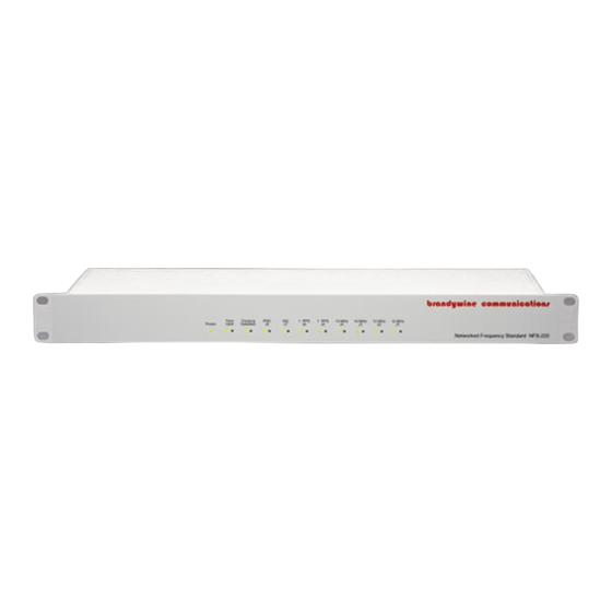
Page 10: Led Indicators
LED Indicators below describes each LED indicator on the front panel of the NFS-220. Table 1 COLOR COMMENT Power Green Indicates Prime Power is applied to the NFS220. Time Valid Green Indicates that the unit has been synchronized to an external reference. -
Page 11: Connections
Connections Table 2 shows the signal interface connections provided on the NFS-220. CONNECTOR REFERENCE CONNECTOR CONNECTOR SIGNAL TYPE J1 10 MHz OUTPUT 1 BNC FEMALE CENTER 10 MHz SHIELD GROUND J2 10 MHz OUTPUT 2 BNC FEMALE CENTER 10 MHz... -
Page 12: Source Impedance Selection And Signal Termination
Source Impedance Selection and Signal Termination Signal/Connector Connector Link Setting Source Impedance Recommended Load Factory Setting Impedance 10 MHz 50 ohm 50 ohm 10 MHz 50 ohm 50 ohm 10 MHz 50 ohm 50 ohm 10 MHz 50 ohm 50 ohm 1PPS 1 LK5 on Low Z... -
Page 13: Unpacking And Installation
P/N 002000150, SLIDE, RACK, 28", 27" TRAVEL, 80 LB Original Manufacturer: General Devices Chassis Trak Type C300. 3.2.2 Power Insert the power cord of the NFS-220 into an electrical socket to power up the unit. The Power LED indicator will illuminate green. 3.2.3 Ethernet Connect one end of an Ethernet patch cable to the NFS-220 Ethernet port J11. - Page 14 (antenna gain - cable loss) be between 10 dB - 33 dB. Using an antenna with 30 dB of gain allows for about 20 dB of cable loss. The NFS-220 is shipped with 100’ of Belden 8240 antenna cable with a cable loss of approximately 18 dB.
-
Page 15: External Gps Receiver (Have Quick/1Pps)
The local fiber and up-converter unit accepts the optical signal and converts it back into an electrical RF signal that is processed by the NFS-220. Please note that the unit does not require calibration. -
Page 16: Ntp Server Connection Example
To change the network address, the user may use a web browser, or the console port. The two processes are described below. If the NFS-220 cannot find a DCHP server on the network, it will set itself to the default IP Address of 192.168.1.220, unless it has already been set to an existing static IP. -
Page 17: Changing Nfs220 Network Ip Address Using Internet Explorer
Changing NFS220 Network IP address using Internet Explorer Enter the IP address of the NFS-220 into the address bar of a web browser running on a computer that is connected to the same network as the NFS-220, as shown in... - Page 18 3. Click on the Submit button. 4. Note that the browser will not reload the page, because the NFS-220 IP address has now changed. 5. Set the browser to the newly configured IP address and confirm that the NFS-220 IP address has changed as desired.
-
Page 19: Latest Version Of Java Software
3.3.2.3 Latest Version of Java Software To properly control and monitor the NFS-220 via a web browser based interface, Java software must be installed on your computer. To obtain the Java software, follow the steps given below. Go to http://www.java.com. -
Page 20: Configuration
The Setup tab consists of two sections, the System and IP Address. This tab allows you to modify setup information for the NFS-220. Please note that a Class C Network is being used therefore valid IP addresses are between 192.0.0.0 to 223.255.255.0. To save all modifications made to the Setup screen, click the Submit button. -
Page 21: Ip Address
Figure 6 Download MIB file This will open a web page that contains the MIB for the NFS-220. Select all of the text on this page (Figure 7) and save it as a .txt file. This .txt file may be compiled by an SNMP application to provide control the NFS-220.. -
Page 22: Figure 7 Nfs-220 Mib (Sample)
Figure 7 NFS-220 MIB (sample) MANUAL P/N 900000111 REV K... -
Page 23: Status
The Status tab consists of four sections Local Time, Reference Status, Oscillator Status, Fault Status. This tab allows you to monitor the functional status of the NFS-220. There are no functions that can be modified on this tab – it is all read-only information. -
Page 24: Oscillator Status
4.2.3 Oscillator Status The NFS-220 contains an internal disciplined oscillator that is used as the basis of the NFS-220 time and frequency outputs. The oscillator is divided down to 1 pulse per second and the difference between this 1pulse per second and the reference 1 pulse per second is measured and displayed as “Phase Error”. -
Page 25: Time
Time, and Daylight Saving Time (Advanced) and Time Code. This tab allows you to modify the time settings for the NFS-220. To save all modifications made to the Time screen, click the Submit button. To undo all modifications made to the Time screen, click the Reset button. -
Page 26: Serial Output (Tod)
Bits, Stop Bits and Parity. The Format refers to the format of the time messages sent from both the RS232 and RS422 serial ports of the NFS-220 once per second. Table 7 below lists the characters and descriptions used in the Format field. The Baud refers to the number of bits transmitted per second. -
Page 27: Time Zone Settings
The Time Zone combo box allows the user to select either hour or minute. The table below lists all time zones and their Standard Time offsets from the Universal Time. Once the time zone has been set, the IRIG output of the NFS-220 will supply time of day with that time zone offset applied. STANDARD TIME OFFSET FROM... -
Page 28: Daylight Saving Time
If the user clicks the check box, the system will automatically adjust the time of the NFS- 220 when daylight saving time occurs. If the user does not click on the check box, the system will not automatically adjust the time of the NFS-220 when daylight saving time occurs. 4.3.4... -
Page 29: Setting The Irig Time Code Format
4.3.5 Setting the IRIG Time Code format. The NFS-220 has two separate time code generators included. One time code generator is fixed to generate Have Quick II time code, as defined in ICD-GPS-060. The second time code generator generates one of 4 IRIG time codes. The selected IRIG time code is generated in two variants- the modulated time code ( J8) and the DC level shift version (DCLS) is output on J9-2. -
Page 30: Password
Password screen, click the Submit button. To undo all modifications made to the Password screen, click the Reset button. IMPORTANT INFORMATION: The default user name and password for the system is BRANDYWINE and the user must always enter a user name and password when submitting changes to the system. -
Page 31: Reference
The Reference tab consists of four sections: Reference, Application, Oscillator Settings and Manual Time Set. This tab allows you to modify the reference for the NFS-220, and to set the output amplitude of the 10 MHz outputs. Please note that while the NFS-220 is acquiring time from the references the Valid Time LED indicator will be extinguished. -
Page 32: Reference Selection
4.5.1.1.1 GPS Fixed Location Application If the fixed location mode is selected, the NFS-220 will begin to survey it’s location by collecting and averaging the position that it computes from the GPS satellites. The averaged position is then stored into the GPS receiver, and the receiver transitions to a timing mode, where the averaged position is assumed correct, and time is only calculated from all satellites in view. -
Page 33: Have Quick & 1Pps Reference
4.5.1.2 Have Quick & 1PPS Reference If the Have Quick & 1PPS reference is selected, the NFS-220 will synchronize to the external 1PPS appearing on J10-4. The epoch of this 1PPS will be determined by decoding the Have Quick time code received on J10-1. -
Page 34: 10 Mhz Output Level Settings
Figure 16 Manual Setting of Time in NFS-220 4.5.2 10 MHz Output Level Settings The Amplitude of each of the four 10MHZ outputs may be individually set by entering a nominal amplitude value on the reference screen. Each individual 10 MHz (J1 through J4) level may be set over a range of 1 to 255. These numbers correspond to voltage levels shown in Figure 17 . -
Page 35: Output Timing Setting
4.5.3.1 Setting 1PPS Pulse width The NFS-220 1PPS outputs are adjustable in both width and phase. The Pulse width may be varied over the range of 100ns to 650µs. Enter the desired pulse width (in nanoseconds) in the box labelled 1PPS Pulse width and press . -
Page 36: Setting 1Pps Pulse Delay
4.5.3.2 Setting 1PPS Pulse delay The NFS220 incorporates a unique feature that allows the three 1PPS outputs to be offset from the main internal time base (which is synchronized to the reference). This feature may be used to compensate for propagation delay in the cables between the NFS220 and the point of use. -
Page 37: Help
Help The Help tab provides the user with help while using difficult areas in the system. Help links are located throughout the entire system so the user has access to the Help screen whenever the user encounters a problem. Once the user clicks on the help link the user will be automatically redirected to the Help screen. -
Page 38: Fpga Upgrade
3. WiseUpdater.exe starts programming the unit. PLEASE DO NOT power down the unit during the programming. FPGA Upgrade 1. Launch NFS_Util.exe and click File/Set COM Port to select an available computer’s COM port. Click OK to save COM setting. MANUAL P/N 900000111 REV K... - Page 39 2. Connect a Null Serial Cable (crossed-over) from the computer’s COM port to the unit’s J10 (Console). 3. Make sure the unit (NFS-220 or NFS-221) is up and running. 4. From NFS_Util.exe, click System/Disable Broadcast. 5. From NFS_Util.exe, click System/Update FPGA and Open File Dialog will open.
-
Page 40: Webpage Upgrade
7. NFS_Util.exe will show the programming status. Webpage Upgrade 1. Recycle power the unit. MANUAL P/N 900000111 REV K... - Page 41 1. Connect a null serial (crossed) cable from an available serial port of the computer to NFS’s Console port (J10). Note: NFS stands for NFS-220, NFS-221, PTU I models. 2. Launch the NFS_Util.exe. Follow the Attention dialog instruction. MANUAL P/N 900000111 REV K...
- Page 42 3. Click File/Set COM Port. Select a correct COM port number and click OK to save the COM port settings. The NFS_Util.exe only shows available COM ports. 4. Make sure the NFS unit is up and running. 5. From the NFS_Util.exe, click System/Disable Broadcast, click System/Request Model Number for communication testing.
- Page 43 7. Click System/Reset to Factory Default. 8. “Reset to Factory Default” message was responded from the NFS unit. MANUAL P/N 900000111 REV K...
- Page 44 9. Cycle power the NFS unit and configure the NFS’s settings as necessary. MANUAL P/N 900000111 REV K...
-
Page 45: Drawings
Drawings FIGURE DESCRIPTION NFS-220 Front Panel NFS-220 Rear Panel Link Settings /Component Location MANUAL P/N 900000111 REV K... - Page 46 NFS 220 Front Panel NFS 220 Rear Panel MANUAL P/N 900000111 REV K...
- Page 47 NFS 220 Link Settings/ Component Location MANUAL P/N 900000111 REV K...
-
Page 48: Link Settings
Link Settings The link settings below can be used to configure the NFS-220 to specific applications. Link settings are changes as follows: There is potentially un-insulated “dangerous voltage” within the NFS-220 enclosure. The “dangerous voltage” may be of sufficient magnitude to constitute as a risk of electrical shock to people. - Page 49 Link Function Factory Default Setting [Reserved for Factory Use only] Table 10 Hardware Link Settings MANUAL P/N 900000111 REV K...
-
Page 50: Appendix A - Serial Output For Firmware Version
Appendix A – Serial Output for firmware version V1.18.00 For firmware version V1.18.00, the serial port is designed to output Time, Position and Velocity. To display this, access the serial port as described in Section 4.3.1 and enter the command “#gp” Date: Wednesday 12/11/13 17:51:00 Field# Description... -
Page 51: Figure 19 - Serial Time, Position And Velocity Output
Track: Field# Description Range Track “9”: Number of Satellites used for Positioning 00-12 Velocity: 344.5,T,331.5,M,000.0,N,000.0,K,A Field# Description Range [Bytes] (unit) 1-2. True Course “344.5” 000.0-359.9 [5](degree) “T”(meaning TRUE) [1](n/a) Note: A null field is output unless true course information is available. 3-4. -
Page 52: Appendix B - Mib File
Appendix B – MIB File and Description Scope This section defines the SNMP message and data format. The Brandywine NFS-220 supports setting 1PPS pulse width, 1PPS offset and analog oscillator amplitudes. An SNMP client has accessed to the system via TCP connection interface. The system uses a standard SNMP data format (SNMP Version 1) for moving the string or integer message type. - Page 53 Set up Trap Table Subtree The size of the Trap table is 5. Once a Trap table entry is created with Trap Enabled set (1=SET), the NFS-220 will generate a Trap whenever an LED output is failed. 8.3.1 trapReceiverNumber Description...
- Page 54 SYNTAX INTEGER (0..4) ACCESS not-accessible STATUS mandatory DESCRIPTION "" ::= { trapEntry 1 } 8.3.2 trapEnabled Description trapEnabled Type MIB Read 1.3.6.1.4.1.18954.5.2.1.1.2.0 Integer MIB Write 1.3.6.1.4.1.18954.5.2.1.1.2.0 Integer Indicates if this trap entry is enabled or not (1=Enable; 0=Disable). trapEnabled OBJECT-TYPE SYNTAX INTEGER ACCESS...
- Page 55 MIB Read 1.3.6.1.4.1.18954.5.2.2.0 IP_ADDRESS MIB Write IP_ADDRESS The IP address will be stored in the Non Volatile Memory after the “WriteNVM” command is issued. IPAddress OBJECT-TYPE SYNTAX IP_ADDRESS ACCESS read-write STATUS mandatory DESCRIPTION "System IP Address" ::= { setup 2 } 8.3.6 IPSubNetAddress Description...
- Page 56 MIB Write 1.3.6.1.4.1.18954.5.2.6.0 Integer The SNMP function writes the values to Non-Volatile memory. Changes made will automatically be loaded into the NFS-220 system the next time the unit is restarted. Use extreme care when issuing this command. WriteNVM OBJECT-TYPE SYNTAX...
- Page 57 B15 B14 B13 B12 B11 B10 B9 System State Warm up Locked Hold over Failed Model OCXO 8.4.2 NTrackSat Description NTrackSat Type MIB Read 1.3.6.1.4.1.18954.5.3.2.0 Integer MIB Write Number of tracking satellites in the position solution. NTrackSat OBJECT-TYPE SYNTAX INTEGER ACCESS read-only STATUS...
- Page 58 GPS Position – Latitude displays in string with format (degree[0-90], minute[0-59], seconds[0-59], and ‘N’ or ‘S’ character) Latitude OBJECT-TYPE SYNTAX DisplayString ACCESS read-only STATUS mandatory DESCRIPTION "GPS Position - Latitude" ::= { status 4 } Ex: 33 degree 45’38” N 8.4.5 Longitude Description...
- Page 59 PhaseErr OBJECT-TYPE SYNTAX DisplayString ACCESS read-only STATUS mandatory DESCRIPTION "Phase Error" ::= { status 7 } 8.4.8 DACVOLT Description DACVOLT Type MIB Read 1.3.6.1.4.1.18954.5.3.8.0 String MIB Write DAC voltage (0-5V). DACVOLT OBJECT-TYPE SYNTAX DisplayString ACCESS read-only STATUS mandatory DESCRIPTION "DAC Volt (0-5V)" ::= { status 8 } 8.4.9 Output Status...
- Page 60 TIME 8.5.1 SerialBaudRate Description SerialBaudRate Type MIB Read 1.3.6.1.4.1.18954.5.4.1.0 Integer MIB Write 1.3.6.1.4.1.18954.5.4.1.0 Integer The Baud rate control register controls the User’s Serial interface. The default baud rate setting is 115200 baud. SerialBaudRateOBJECT-TYPE SYNTAX INTEGER ACCESS read-write STATUS mandatory DESCRIPTION "Serial Baud Rate 115.2K to 4.8K " ::= { time 1 } B15 B14 B13 B12 B11 B10 B9 DB1 DB0 SB0 P1...
- Page 61 OBJECT IDENTIFIER ::= { NFS 5 } ON-OFF INTEGER { ON(1), OFF(0) } -- product number ProductName OBJECT-TYPE SYNTAX DisplayString ACCESS read-only STATUS mandatory DESCRIPTION "NFS-220 or NFS-220 TCXO" ::= { Product 1 } SerialNumber OBJECT-TYPE SYNTAX DisplayString (SIZE (0..11)) ACCESS read-only STATUS mandatory DESCRIPTION "Serial Number string."...
- Page 62 ::= { Product 2 } Version OBJECT-TYPE SYNTAX DisplayString ACCESS read-only STATUS mandatory DESCRIPTION "Version string. e.g. 1.05 Build 1000." ::= { Product 3 } Date OBJECT-TYPE SYNTAX DisplayString ACCESS read-only STATUS mandatory DESCRIPTION "Date of version" ::= { Product 4 } -- setup 1 Traps OBJECT-TYPE SYNTAX SEQUENCE OF TrapEntry...
- Page 63 TrapEnabled OBJECT-TYPE SYNTAX INTEGER { Yes(1), No(0) } ACCESS read-write STATUS mandatory DESCRIPTION "Indicates if this trap entry is enabled or not." ::= { TrapEntry 2 } TrapReceiverIPAddress OBJECT-TYPE SYNTAX IpAddress ACCESS read-write STATUS mandatory DESCRIPTION "Trap receiver IP address" ::= { TrapEntry 3 } TrapCommunity OBJECT-TYPE SYNTAX...
- Page 64 STATUS mandatory DESCRIPTION "Save NVM. WriteNVM needs to set at last after any change was made." ::= { Setup SoftReset OBJECT-TYPE SYNTAX INTEGER ACCESS read-write STATUS mandatory DESCRIPTION "Soft Reset" ::= { Setup -- Status SysState OBJECT-TYPE SYNTAX INTEGER ACCESS read-only STATUS mandatory...
- Page 65 SYNTAX DisplayString ACCESS read-only STATUS mandatory DESCRIPTION "Phase Error" ::= { Status DACVOLT OBJECT-TYPE SYNTAX DisplayString ACCESS read-only STATUS mandatory DESCRIPTION "DAC Volt (0-5V)" ::= { Status OutputStatus OBJECT-TYPE SYNTAX INTEGER ACCESS read-only STATUS mandatory DESCRIPTION "Output Status" ::= { Status -- Time SerialBaudRate OBJECT-TYPE...
- Page 66 ::= { Time -- ref SelectReference OBJECT-TYPE SYNTAX INTEGER ACCESS read-write STATUS mandatory DESCRIPTION "Select Reference. Request current reference input (0=GPS, 1=HQ, 2=External 1PPS or 3=Freerun). Use TOD command to set time for the external 1PPS reference input." ::= { Reference 1 } Mode OBJECT-TYPE SYNTAX INTEGER...
- Page 67 PulseOffset1 OBJECT-TYPE SYNTAX DisplayString ACCESS read-write STATUS mandatory DESCRIPTION "" ::= { Reference 8 PulseOffset2 OBJECT-TYPE SYNTAX DisplayString ACCESS read-write STATUS mandatory DESCRIPTION "" ::= { Reference 9 PulseOffset3 OBJECT-TYPE SYNTAX DisplayString ACCESS read-write STATUS mandatory DESCRIPTION "" ::= { Reference 10 } TODCounter OBJECT-TYPE SYNTAX...
Need help?
Do you have a question about the NFS-220 and is the answer not in the manual?
Questions and answers