Table of Contents
Advertisement
Quick Links
Aspect Medical Systems
BISPECTRAL INDEX™ (BIS™)
MONITORING SYSTEM
OPERATING MANUAL
© Copyright, 2006, Aspect Medical Systems. All rights reserved. Copying or other
reproduction of this document is prohibited without prior written consent of Aspect
Medical Systems.
Aspect Medical Systems, Inc.
One Upland Road
Norwood, MA 02062
U.S.A.
(Tel) 617-559-7000
(Tel) 888-BIS INDE(X) (U.S. only)
(Fax) 617-559-7400
bis_info@aspectms.com
www.aspectmedical.com
A-2000™
Rx only
EC REP
Aspect Medical Systems International B.V.
Rijnzathe 7d2
3454 PV De Meern
The Netherlands
Tel: +31.30.662.9140
Fax: +31.30.662.9150
amsint@aspectms.com
0123
070-0015 3.04
Advertisement
Table of Contents

Summary of Contents for Aspect A-2000 BIS
- Page 1 BISPECTRAL INDEX™ (BIS™) MONITORING SYSTEM OPERATING MANUAL Rx only © Copyright, 2006, Aspect Medical Systems. All rights reserved. Copying or other reproduction of this document is prohibited without prior written consent of Aspect Medical Systems. EC REP Aspect Medical Systems, Inc.
- Page 2 Considerations for Using BIS Monitoring Clinical judgment should always be used when interpreting the BIS in conjunction with other available clinical signs. Reliance on the BIS alone for intraoperative anesthetic management is not recommended. As with any monitored parameter, artifacts and poor signal quality may lead to inappropriate BIS values.
-
Page 3: Table Of Contents
2.2.3 P ..........2-3 OWER EQUIREMENTS AND YSTEM ROUNDING 2.2.4 S ............2-3 REPARATION OUNTING THE ONITOR 2.3 THE A-2000 BIS MONITORING SYSTEM - EQUIPMENT AND SUPPLIES ..2-5 2.3.1 T BIS M ....................2-6 ONITOR 2.3.2 D (DSC) ..............2-10 IGITAL IGNAL ONVERTER 2.3.3 P (PIC) ...............2-10... - Page 4 3.4 THE A-2000 SOFTWARE MENUS AND MENU SELECTIONS ......3-9 3.4.1 M : ....................3-9 AVIGATION 3.4.2 T ....................3-10 ETUP 3.4.3 T ................3-12 DVANCED ETUP 3.4.4 D ................3-16 ISPLAY ARAMETER ETUP 3.4.5 T ..................3-18 IAGNOSTIC 3.4.6 A .....................3-18 LARM 3.4.7 L ................3-21 ANGUAGE ELECTION 3.4.8 S...
- Page 5 5.2.24 D ............5-6 RANSFER AND OFTWARE PDATES 5.2.25 P .....................5-7 RINTED EPORTS 6 PREVENTIVE MAINTENANCE, CARE AND CLEANING ........6-1 6.1 CARE AND CLEANING ..................6-1 6.2 ROUTINE MAINTENANCE ...................6-2 6.3 FUSE REPLACEMENT ..................6-3 6.4 SYSTEM CHECKOUT...................6-4 6.5 TECHNICAL DOCUMENTATION .................6-5 6.6 INSTRUMENT IDENTIFICATION................6-5 7 DIAGNOSTICS AND TROUBLESHOOTING ............7-1 7.1 THE DIAGNOSTIC MENU..................7-1 7.1.1 DSC S...
- Page 6 TABLE OF FIGURES Figure 1 - Symbol Key....................1-5 Figure 2 Pole Clamp .....................2-4 Figure 3 The A-2000 BIS Monitoring System..............2-5 Figure 4 Front Panel (Example Illustration)..............2-6 Figure 5 Front Panel Controls ..................2-7 Figure 6 Rear Panel ......................2-8 Figure 7 BIS Sensor Connections................2-12 Figure 8 Connecting the PIC (BIS XP Platform and XP Compatible) ......3-2...
-
Page 7: About This Manual
This Operating Manual contains all of the information you need to set up and operate the Aspect Medical Systems’ A-2000 BIS Monitoring System (Figure 3). It also includes specific cleaning and test procedures you may occasionally be required to perform. -
Page 8: Introducing The A-2000 Bis Monitoring System
INTRODUCING THE A-2000 BIS MONITORING SYSTEM INDICATIONS FOR USE The Aspect A-2000 EEG Monitor with BIS is intended for use under the direct supervision of a licensed healthcare practitioner or by personnel trained in its proper use. The BIS Monitor is intended for use on adult and pediatric patients within a hospital or medical facility providing patient care to monitor the state of the brain by data acquisition of EEG signals. -
Page 9: Safety Precautions
SECTION 1 SAFETY PRECAUTIONS ______________________________________________________________________ SECTION 1 SAFETY PRECAUTIONS INTRODUCTION Caution: Carefully read this entire manual before using the monitor in a clinical setting. WARNINGS, CAUTIONS, AND NOTES The terms warning, caution, and note have specific meanings in this manual. •... - Page 10 SECTION 1 SAFETY PRECAUTIONS ______________________________________________________________________ FOR PROPER GROUNDING, THE POWER RECEPTACLE MUST BE A THREE-WIRE GROUNDED OUTLET. A HOSPITAL GRADE OUTLET IS REQUIRED. NEVER ADAPT THE THREE-PRONG PLUG FROM THE MONITOR TO FIT A TWO-SLOT OUTLET. IF THE OUTLET HAS ONLY TWO SLOTS, MAKE SURE THAT IT IS REPLACED WITH A THREE-SLOT GROUNDED OUTLET BEFORE ATTEMPTING TO OPERATE THE MONITOR.
- Page 11 The A-2000 has been designed to operate with a disposable BIS Sensor. The sensor is a silver/silver chloride electrode array that utilizes Aspect's patented Zipprep technology and uses a proprietary connector. Use of other electrodes is not recommended.
- Page 12 Damage due to electrostatic discharge may result. A-2000 is a trademark of Aspect Medical Systems, Inc. Bispectral Index, BIS, the BIS logo, and Zipprep are trademarks of Aspect Medical Systems, Inc. and are registered in the U.S.A., E.U. and other countries.
-
Page 13: Figure 1 - Symbol Key
SECTION 1 SAFETY PRECAUTIONS ______________________________________________________________________ 1.3 KEY TO SYMBOLS ON (power; connection to the mains) OFF (power; disconnection from the mains) Audible Alarm Silenced Operating on Battery Type BF Equipment Type BF Equipment Defibrillator-proof Attention, Consult Accompanying Documents Attention, J1 RS-232 Serial Port, Consult Accompanying Documents Attention, J2 Printer Port, Consult Accompanying Documents... - Page 14 SECTION 1 SAFETY PRECAUTIONS ______________________________________________________________________ Fuse, Replace only with same Type and Rating Equipotential Alternating Current Dangerous Voltage Protective Earth (ground) Storage Temperature Limits Figure 1 Symbol Key (concluded).
-
Page 15: Installation And Preparation For Use
INSTALLATION AND PREPARATION FOR USE ______________________________________________________________________ SECTION 2 INSTALLATION AND PREPARATION FOR USE ____________________________________________________ INTRODUCTION This section provides installation instructions for the Aspect A-2000 BIS Monitor, Digital Signal Converter, and accessories. It includes: • Installation checklist • Proper environment •... -
Page 16: Environment
ATMOSPHERE OR WHERE CONCENTRATIONS OF FLAMMABLE ANESTHETICS MAY OCCUR. Temperature: The Aspect A-2000 Monitor is designed to operate safely at a room temperature of 5°C to 40°C. Conditions that exceed these limits could affect reliability. Humidity: The monitor is designed to operate within specifications at a relative non- condensing humidity of 15% to 95%. -
Page 17: Power Requirements And System Grounding
______________________________________________________________________ 2.2.3 Power Requirements and System Grounding The A-2000 BIS Monitor requires a power source of 100-240 VAC, 50-60Hz. Current consumption is 1 ampere maximum (including printer load). To protect operating personnel and patients, the monitor must be properly grounded. -
Page 18: Figure 2 Pole Clamp
5. Replace black knob screw. 6. To attach to pole, place pole within clamp bracket and tighten screw using the black finger knob. 2.2.4.3 Optional Mounting Accessories For information on optional mounting accessories, request Aspect’s “Monitor Mounting Solutions” booklet (part number 070-0031) -
Page 19: The A-2000 Bis Monitoring System - Equipment And Supplies
A pole clamp is also included; however its use is optional. The exact model of DSC, PIC and compatible sensors depends on the system configuration. Please consult section 2.2.4 for more detail. Contact Aspect or your local representative for information on additional equipment and accessories. -
Page 20: The Bis Monitor
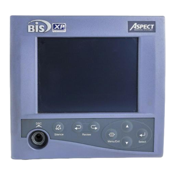
SECTION 2 INSTALLATION AND PREPARATION FOR USE ______________________________________________________________________ 2.3.1 The BIS Monitor 2.3.1.1 Front Panel The front panel of the BIS Monitor contains the Digital Signal Converter (DSC) port and the controls needed for normal operation. See Figure 4. μ 25 mm/sec v/div 29 Mar 2001... -
Page 21: Figure 5 Front Panel Controls
The rear panel components are pictured in Figure 6. They include: the fan, clamp shoe, potential equalization terminal, power cord receptacle with fuse holder, and the RS-232 serial port. A printer connection port is located on the bottom underside of the monitor. Only an Aspect-supplied printer will function with this port. -
Page 22: Figure 6 Rear Panel
Figure 6 Rear Panel WARNING! REPLACE FUSES ONLY WITH ONE OF THE FOLLOWING PARTS: Aspect P/N 430-0006, 1.25 Amps, 250V, 5x20mm Littelfuse 217 Series, 1.25 Amps, 250V, 5x20mm Wickmann 193 Series, 1.25 Amps, 250V, 5x20mm ALWAYS REPLACE BOTH FUSES TOGETHER, EVEN IF ONLY ONE... - Page 23 The power cord receptacle is used to plug in a three-prong hospital grade power cord to provide power to the monitor and to the DSC when attached. The printer port is provided to attach the monitor to the Aspect A-2000 Printer. Caution: The A-2000 system complies with the electromagnetic compatibility requirements of EN60601-1-2.
-
Page 24: Digital Signal Converter (Dsc)
Service or repairs must be performed only by qualified biomedical technicians. 2.3.3 Patient Interface Cable (PIC) Aspect's BIS Sensor Patient Interface Cable (see Figure 3) connects the DSC to the BIS Sensor. 2.3.4 BIS Sensor After the BIS Sensor has been placed correctly on the patient's head, it is connected to the PIC. -
Page 25: A-2000 System Configurations
BIS Pediatric BIS Pediatric * Some early versions of the A-2000 BIS XP Platform may be supplied with a DSC-3 ** BIS Sensor Plus (where sold) is also compatible with the BIS XP Platform and XP Compatible Systems 2.3.5.1 The BIS XP Platform The BIS XP Platform represents Aspect’s top-of-the-line BIS monitoring solution. -
Page 26: Platform Compatibility Considerations
______________________________________________________________________ 2.3.6 Platform Compatibility Considerations Aspect’s new sensors (BIS Quatro, BIS Extend and BIS Pediatric) are only compatible with new BIS systems (BIS XP Platform and XP Compatible) by virtue of an improved sensor connector (see figure below) and other features. -
Page 27: Cable Connections
SECTION 2 INSTALLATION AND PREPARATION FOR USE ______________________________________________________________________ 2.4 CABLE CONNECTIONS After you have familiarized yourself with the safety information in the introductory section of this manual and have prepared a suitable environment, follow these steps to prepare the A-2000 system for operation. 1. -
Page 28: Language Selection Menu
SECTION 2 INSTALLATION AND PREPARATION FOR USE ______________________________________________________________________ 2.6.1 Language Selection Menu The A-2000 is designed to support multiple languages. If the screen does not display the desired language, follow these steps to display the Language Selection Menu: 1. Press [MENU/EXIT] to access the Setup Menu. 2. - Page 29 SECTION 2 INSTALLATION AND PREPARATION FOR USE ______________________________________________________________________ 3. Press [SELECT]. 4. Highlight Save Settings using the up [↑] or down [↓] arrows. 5. Press [SELECT] to save setting changes. The current settings will be saved and the system will exit to the Main Screen. Note: The Save Settings option is disabled when in Battery Backup-Low Power condition.
- Page 30 SECTION 2 INSTALLATION AND PREPARATION FOR USE ______________________________________________________________________ 2-16...
-
Page 31: Operating The A-2000
The A-2000 has been designed to operate with a disposable BIS Sensor. The sensor is a silver/silver chloride electrode array that utilizes Aspect's patented Zipprep technology and uses a proprietary connector. Use of other electrodes is not recommended. -
Page 32: Figure 8 Connecting The Pic (Bis Xp Platform And Xp Compatible)
SECTION 3 OPERATING THE A-2000 ______________________________________________________________________ WARNINGS! THE CONDUCTIVE PARTS OF ELECTRODES OR SENSOR AND CONNECTORS, INCLUDING THE NEUTRAL ELECTRODE, SHOULD NOT CONTACT OTHER CONDUCTIVE PARTS, INCLUDING EARTH. TO REDUCE THE HAZARD OF BURNS IN THE HIGH-FREQUENCY SURGICAL NEUTRAL ELECTRODE CONNECTION, THE SENSOR OR ELECTRODES SHOULD NOT BE LOCATED BETWEEN THE SURGICAL SITE AND THE ELECTRO-SURGICAL UNIT RETURN ELECTRODE. -
Page 33: The Sensor Check And Sensor Integrity Check
SECTION 3 OPERATING THE A-2000 ______________________________________________________________________ 3.2 THE SENSOR CHECK AND SENSOR INTEGRITY CHECK A Sensor Check is initiated automatically when the sensor and PIC are connected to the DSC. It may also be initiated by the user in the Setup Menu. Figure 9 The Sensor Check (BIS Standard and BIS Pediatric sensors) -
Page 34: Figure 10 The Sensor Check (Bis Quatro And Bis Extend)
SECTION 3 OPERATING THE A-2000 ______________________________________________________________________ Figure 10 The Sensor Check (BIS Quatro and BIS Extend) The impedance value for each electrode, in kilo ohms, appears on the screen along with its status: PASS - An electrode passes if the impedance for that electrode is less than 7.5 kilo ohms. -
Page 35: The Bis Trend Screen Display
SECTION 3 OPERATING THE A-2000 ______________________________________________________________________ 3.3 THE BIS TREND SCREEN DISPLAY Once the sensor check has successfully completed, monitoring begins and the appropriate information appears on the screen. The BIS trend screen consists of four separate regions (see Figure 11): •... -
Page 36: The Signal Quality Region
SECTION 3 OPERATING THE A-2000 ______________________________________________________________________ 3.3.2 The Signal Quality Region The Signal Quality Region is located in the upper right section of the screen. When the [MENU/EXIT] key has been pressed, this area is used to display the Setup Menu. In the BIS Log display, it displays instructions. -
Page 37: The Message Region
SECTION 3 OPERATING THE A-2000 ______________________________________________________________________ Figure 12 The BIS Trend Display with BIS Extend Sensor in Use 3.3.3 The Message Region The Message Region is a space reserved for text that appears below the BIS and Signal Quality Regions and extends the full width of the screen. Status and error messages are displayed here. -
Page 38: Figure 13 The Bis Trend Display
SECTION 3 OPERATING THE A-2000 ______________________________________________________________________ During periods of poor signal quality when SQI is below 50, an artifact bar appears along the horizontal axis at the bottom of the graph area. It appears as a hatched line. When signal quality is considered too low to calculate a BIS value, this bar will show prominently as solid white and any trend variables that are adversely affected by artifact will not be displayed. -
Page 39: The A-2000 Software Menus And Menu Selections
SECTION 3 OPERATING THE A-2000 ______________________________________________________________________ 3.4 THE A-2000 SOFTWARE MENUS AND MENU SELECTIONS This section discusses the A-2000 software menus and menu selections, including: • Setup Menu • Advanced Setup Menu • Display Parameter Setup screen • Diagnostic Menu •... -
Page 40: The Setup Menu
SECTION 3 OPERATING THE A-2000 ______________________________________________________________________ 3.4.2 The Setup Menu The Setup Menu can generally be accessed by pressing the [MENU/EXIT] key. Before using the monitor for the first time, you may want to update the Setup Menu with your desired screen settings and the current date and time. - Page 41 SECTION 3 OPERATING THE A-2000 ______________________________________________________________________ Sensor Check - Sensor impedance checks are initiated automatically when the PIC and sensor are attached to the DSC. You may initiate another check at any time by selecting this option. To initiate the check: 1.
-
Page 42: The Advanced Setup Menu
SECTION 3 OPERATING THE A-2000 ______________________________________________________________________ 3.4.3 The Advanced Setup Menu The Advanced Setup Menu is used to select infrequently changed parameters. You may need to access the Advanced Setup Menu before using the system for the first time to set the date and time and to save any settings that were changed in the Setup Menu so they will not be lost when the monitor is powered off. - Page 43 SECTION 3 OPERATING THE A-2000 ______________________________________________________________________ Time/Date To set the current time and date: 1. Press [MENU/EXIT] to access the Setup Menu. 2. Highlight Advanced Setup using the up [↑] or down [↓] arrows. 3. Press [SELECT]. 4. Highlight Time/Date using the up [↑] or down [↓] arrows. 5.
- Page 44 SECTION 3 OPERATING THE A-2000 ______________________________________________________________________ 2. Highlight Advanced Setup using the up [↑] or down [↓] arrows. 3. Press [SELECT]. 4. Highlight Diagnostic Menu using the up [↑] or down [↓] arrows. 5. Press [SELECT]. Use of the Diagnostic Menu is covered in Section 7, "Diagnostics and Troubleshooting". Alarm Menu –...
- Page 45 SECTION 3 OPERATING THE A-2000 ______________________________________________________________________ Language Selection Menu – The A-2000 is designed to support multiple languages. To display the Language Selection Menu: 1. Press [MENU/EXIT] to access the Setup Menu. 2. Highlight Advanced Setup using the up [↑] or down [↓] arrows. 3.
-
Page 46: Display Parameter Setup
SECTION 3 OPERATING THE A-2000 ______________________________________________________________________ 3.4.4 Display Parameter Setup This menu allows the user to view or change basic system parameters. Display Parameter Setup Dual EEG Display Filters EEG Sweep Speed 15 25 30 (mm/sec) EEG Amplitude 10 25 50 100 (uv/div) BIS Log Interval 15 60... - Page 47 SECTION 3 OPERATING THE A-2000 ______________________________________________________________________ Filters - The A-2000 uses filters to screen out undesirable interference from the raw EEG signal display. If you prefer to observe the raw EEG without the filters, they may be turned off. To turn the Filters off: 1.
-
Page 48: The Diagnostic Menu
SECTION 3 OPERATING THE A-2000 ______________________________________________________________________ BIS Log Interval (minutes) – The interval at which the BIS values are reported in the BIS Log display can be set to 1, 5, 15, or 60 minutes. To set the BIS Log Interval: 1. - Page 49 SECTION 3 OPERATING THE A-2000 ______________________________________________________________________ High Alarm Limit - A high alarm limit may be set so that you are notified when the BIS number reaches a particular high level. If the BIS number reaches the high limit, the BIS number displayed on the screen will alternate from a solid display to an outlined display (when signal quality is good).
- Page 50 SECTION 3 OPERATING THE A-2000 ______________________________________________________________________ Note: Turning a limit alarm OFF differs from pressing the front panel [SILENCE] in that OFF disables audible and visible alarms for the BIS alarm limit only. The Alarm Silence key disables all audible alarms but does not disable visual alarms.
-
Page 51: Language Selection Menu
SECTION 3 OPERATING THE A-2000 ______________________________________________________________________ 3.4.7 Language Selection Menu The A-2000 is designed to support multiple languages. Figure 19 The Language Selection Menu To change languages: 1. Press [MENU/EXIT] to access the Setup Menu. 2. Highlight Advanced Setup using the up [↑] or down [↓] arrows, then press [SELECT]. -
Page 52: Alternative Displays
SECTION 3 OPERATING THE A-2000 ______________________________________________________________________ 3.5 ALTERNATIVE DISPLAYS Alternative screen displays can be requested in the Setup Menu. These displays are: DSA, EEG and BIS Log. μ v/div 25 mm/sec 29 Mar 2001 13:01:52 CASE:Ab9r SEF: 17.2 AMPL 12:57 12:58 12:59 13:00... -
Page 53: The Eeg Display
SECTION 3 OPERATING THE A-2000 ______________________________________________________________________ During periods of poor signal quality (below 50), hatched artifact bars appear between the DSA and AMPL graphs. When signal quality is too low for BIS, these bars will show prominently as solid white and the DSA, total power, and spectral edge information will not be displayed. -
Page 54: The Bis Log Display
SECTION 3 OPERATING THE A-2000 ______________________________________________________________________ 3.5.3 The BIS Log Display This display shows the BIS numeric values over time (up to 400 hours) and is updated continually as each value is calculated. Each line shows a one-minute sample of the minimum and maximum BIS values along with the average BIS, EMG, SR (Suppression Ratio), SQI (Signal Quality Index), and BURST (Burst Count) values during the previous one-minute period. -
Page 55: Figure 23 The Bis Log Display - Review Mode
SECTION 3 OPERATING THE A-2000 ______________________________________________________________________ Figure 23 The BIS Log Display – Review Mode Previous / Next: Use the left [←] arrow on the keypad to display the previous screen of data (earlier times). Use the right [→] arrow key to view the next screen of data (later times). - Page 56 SECTION 3 OPERATING THE A-2000 ______________________________________________________________________ Max BIS: The maximum value for BIS during the previous minute. For example, if the time listed is 09:00, the maximum value recorded from 8:59:01 through 09:00:00 is displayed. Min BIS: The minimum value for BIS during the previous minute. Average BIS, EMG, SR, SQI, BURST: The average values for BIS, EMG, Suppression Ratio, Signal Quality Index and Burst Count during the previous minute.
-
Page 57: Reviewing Stored Trend Data
SECTION 3 OPERATING THE A-2000 ______________________________________________________________________ 3.6 REVIEWING STORED TREND DATA Up to 11 hours of trend information may be viewed in Review Mode. (See Figure 24). To review information, press the left [←] or right [→] arrow key. The Signal Quality Region of the screen will indicate that you have entered Review Mode. -
Page 58: Ending A Case
HANDS ARE CLEAN AND DRY BEFORE TOUCHING THE POWER CORD. 3.8 DATA TRANSFER BIS values and other EEG data may be acquired from the monitor using the RS-232 serial port. Please contact Aspect Medical Systems for instructions. (See back cover for contact information.) 3-28... -
Page 59: Software Updates
SECTION 3 OPERATING THE A-2000 ______________________________________________________________________ 3.9 SOFTWARE UPDATES The A-2000 monitor will automatically begin a software update if a software update device, attached to the serial port, is detected when the monitor power is turned on. Follow these steps to perform the update: 1. - Page 60 SECTION 3 OPERATING THE A-2000 ______________________________________________________________________ 3-30...
-
Page 61: Quick Reference Guide
QUICK REFERENCE GUIDE This “Quick Reference Guide” is intended only as an operating checklist for users already familiar with the A-2000 BIS Monitor. Do not proceed unless you have read the “Important Safety Precautions” (Section 1 of this manual). BASIC OPERATION... - Page 62 SECTION 4 QUICK REFERENCE GUIDE ______________________________________________________________________ If you want to: Do this: • • Press [MENU/EXIT] from the Main Mark an event • Screen to get to the Setup Menu. Initiate a sensor check • Use the arrows to highlight your choice. •...
- Page 63 SECTION 4 QUICK REFERENCE GUIDE ______________________________________________________________________ If you want to: Do this: • Change the serial port protocol • Press [MENU/EXIT] from the Main • Enable / disable extended memory Screen to get to the Setup Menu, then recording select Advanced Setup Menu. •...
- Page 64 SECTION 4 QUICK REFERENCE GUIDE ______________________________________________________________________...
-
Page 65: Features And Capabilities
SECTION 5 FEATURES AND CAPABILITIES ____________________________________________________ INTRODUCTION This section includes: • How the A-2000 BIS Monitoring System works • Display Configurations • Other System Features 5.1 HOW THE A-2000 MONITORING SYSTEM WORKS A sensor placed on the patient’s head transmits EEG signals to the Digital Signal Converter. -
Page 66: Electromyograph (Emg) Indicator
SECTION 5 FEATURES AND CAPABILITIES ______________________________________________________________________ 5.2.3 Electromyograph (EMG) Indicator EMG 70-110 Hz Bar Graph Display Range 30 – 55dB The power (in decibels) in the frequency range 70-110 Hz is labeled “EMG.” This frequency range contains power from muscle activity (i.e., electromyography or “EMG”) as well as power from other high-frequency artifacts. -
Page 67: Density Spectral Array (Dsa)
SECTION 5 FEATURES AND CAPABILITIES ______________________________________________________________________ 5.2.8 Density Spectral Array (DSA) The Density Spectral Array (DSA) shows changes in the power spectrum distribution over time. Brighter points on the display correspond to greater power content (on the printout this is reversed, i.e., darker points correspond to greater power content). The total amplitude of the signal is shown by an amplitude bar (based on a decibel scale) that is displayed beside the DSA plot. -
Page 68: Bis Trend Smoothing
SECTION 5 FEATURES AND CAPABILITIES ______________________________________________________________________ 5.2.14 BIS Trend Smoothing The A-2000 offers two choices of smoothing rates over which the BIS value is averaged: • 15 seconds (Provides increased responsiveness to state changes, such as induction or awakening). This is the default setting except when a BIS Extend Sensor is attached or the system is set to ICU mode. -
Page 69: System Self-Checks
SECTION 5 FEATURES AND CAPABILITIES ______________________________________________________________________ 5.2.20 System Self-Checks The A-2000 monitor has several self-checking features to ensure that the system is operating properly. These include: System Check Initiated when the unit is powered on, this test makes certain that system software and hardware components are functioning properly. -
Page 70: Saved Settings
Data may be transferred to and from the A-2000 monitor using the Serial port on the back panel. Request the Aspect A-2000 Serial Port Specification (P/N 070-0017) for a complete description of the protocols. This port is also used to easily upgrade system software. -
Page 71: Printed Reports
SECTION 5 FEATURES AND CAPABILITIES ______________________________________________________________________ 5.2.25 Printed Reports A printer port connector allows connection to the Aspect A-2000 Printer. - Page 72 SECTION 5 FEATURES AND CAPABILITIES ______________________________________________________________________...
-
Page 73: Preventive Maintenance, Care And Cleaning
SECTION 6 PREVENTIVE MAINTENANCE, CARE AND CLEANING ______________________________________________________________________ SECTION 6 PREVENTIVE MAINTENANCE, CARE AND CLEANING INTRODUCTION This section describes: • Care and cleaning procedures • Routine maintenance. 6.1 CARE AND CLEANING WARNING! UNIVERSAL PRECAUTIONS SHALL BE OBSERVED TO PREVENT CONTACT WITH BLOOD OR OTHER POTENTIALLY INFECTIOUS MATERIALS. -
Page 74: Routine Maintenance
The A-2000 contains an internal Nickel-Metal-Hydride battery. The battery must be removed by a qualified service technician and disposed of or recycled in accordance with the national laws of the country. Contact Aspect Medical Systems, Inc. or the local distributor for servicing of battery. -
Page 75: Fuse Replacement
Leakage current is a primary indicator of electrical shock hazard to personnel making contact with any exposed outer surface of the equipment. Each A-2000 BIS Monitor is carefully checked at the factory to verify that leakage current meets the UL2601 and IEC601-1 safety standards. -
Page 76: System Checkout
SECTION 6 PREVENTIVE MAINTENANCE, CARE AND CLEANING ______________________________________________________________________ 6.4 SYSTEM CHECKOUT 1. Secure all components. • Monitor with power cable • • PIC (Patient interface cable, connects DSC to patient) • BIS Sensor or test sensor. 2. Connect power cable to monitor, plug power plug into appropriate wall outlet. 3. -
Page 77: Technical Documentation
This A-2000 Operator Manual contains the maintenance and diagnostic troubleshooting information necessary for customer qualified technical personnel to test and replace those parts of the equipment that are replaceable by the customer. Aspect does not authorize nor provide information to service or repair the internal components of the A-2000. - Page 78 SECTION 6 PREVENTIVE MAINTENANCE, CARE AND CLEANING ______________________________________________________________________...
-
Page 79: Diagnostics And Troubleshooting
SECTION 7 DIAGNOSTICS AND TROUBLESHOOTING ______________________________________________________________________ SECTION 7 DIAGNOSTICS AND TROUBLESHOOTING ____________________________________________________ INTRODUCTION This section details: • The Diagnostic Menu • System and patient messages and appropriate operator actions • What to do if the A-2000 requires service. 7.1 THE DIAGNOSTIC MENU The Diagnostic Menu is designed to help you trace the source of problems you may be experiencing with the A-2000 system. -
Page 80: Dsc Self -Test
A-2000 monitor. If you are experiencing problems with the sensor, check this screen and note the appropriate sensor information before contacting Aspect. The latest sensor used will display first. Information about other sensors may be displayed by using the up and down arrows to scroll through the sensor database. -
Page 81: Clear Data
SECTION 7 DIAGNOSTICS AND TROUBLESHOOTING ______________________________________________________________________ 7.1.4 Clear Data This option clears all data from the system memory and starts a new case. 1. Press [MENU/EXIT] to access the Setup Menu. 2. Highlight Clear Data, using the [↑] or [↓] arrows. 3. - Page 82 The customer retains rights to access this data and Aspect will not access the data without permission of the customer. Occasionally, Aspect may seek such permission to evaluate performance of the A- 2000 monitor and to provide user feedback.
-
Page 83: System Error Message Alarms
SECTION 7 DIAGNOSTICS AND TROUBLESHOOTING ______________________________________________________________________ 7.2 SYSTEM ERROR MESSAGE ALARMS Equipment alarm messages, lead connection, and patient condition alarms (i.e., EEG isoelectric condition) will appear in the message region of the display and an alarm sequence (two tones, high/low, that sounds like “Uh-oh”) will sound when any of the following conditions occur: Digital Signal Converter becomes disconnected, patient electrode leads come off, electrode impedance check fails, or Digital Signal Converter has a power fault. - Page 84 SECTION 7 DIAGNOSTICS AND TROUBLESHOOTING ______________________________________________________________________ E12 Message: Illegal Sensor Type An unrecognized Patient Interface Cable/Sensor has been Operator Action: connected to the DSC. Make sure that the PIC connector is clean and dry. (See Section 6.1). The PIC or Sensor may be defective.
- Page 85 SECTION 7 DIAGNOSTICS AND TROUBLESHOOTING ______________________________________________________________________ E28 Message: SQI Too Low For BIS The Signal Quality Index is unacceptable therefore the Trend Operator Action: variable cannot be calculated. Check Sensor. This may occur as a result of artifact such as those generated from motion or eyeblinks.
- Page 86 SECTION 7 DIAGNOSTICS AND TROUBLESHOOTING ______________________________________________________________________ E45 Message: No Updates From BIS Engine No processed data from BIS Engine in the last 10 seconds. If Operator Action: error persists, monitor may require service. E46 Message: BIS Engine Not Responding BIS Engine is not performing commands within the allowed Operator Action: time limits.
- Page 87 SECTION 7 DIAGNOSTICS AND TROUBLESHOOTING ______________________________________________________________________ E83 Message: Printer Head is Up The print head on the printer has been lifted. Return it to the Operator Action: closed position. If the error persists, the printer requires service. E84 Message: Printer Disconnected The printer is no longer connected to the A-2000.
-
Page 88: What To Do If The A-2000 Requires Service
FRAGILE. • If the repair or replacement is covered by the warranty, Aspect will bear the costs of shipping the repaired or replacement product back to the user. All other shipping costs shall be paid by the user. -
Page 89: Specifications, Warranty And Software License Agreement
______________________________________________________________________ SECTION 8 SPECIFICATIONS, WARRANTY AND SOFTWARE LICENSE AGREEMENT __________________________________________________________ 8.1 SPECIFICATIONS This section lists specifications for the Aspect A-2000 BIS Monitor. General Specifications: • BIS (Bispectral Index) monitor for display of Product Description: processed data and real-time EEG waveforms •... - Page 90 SECTION 8 SPECIFICATIONS, WARRANTY AND SOFTWARE LICENSE AGREEMENT EEG Specifications: • 2 seconds Epoch Duration: • Automatic Artifact Rejection: • 25 μV/div (+/- 1 mV Full Scale) EEG Scales: Display Type – EEG: 5, 10, 25, 50 or 100 μV/div •...
- Page 91 SECTION 8 SPECIFICATIONS, WARRANTY AND SOFTWARE LICENSE AGREEMENT Type of Protection against Electric Shock of the System: Class 1: Equipment in which protection against electric shock does not rely on basic insulation only, but which includes an additional safety precaution. Means are provided for the connection of the equipment to the protective earth conductor in the fixed wiring of the installation in such a way that accessible metal parts cannot become live in the event of a failure of the basic insulation.
-
Page 92: Warranty
SOFTWARE LICENSE AGREEMENT 8.2 WARRANTY Aspect warrants to the initial Purchaser that the A-2000 BIS monitor and the Digital Signal Converter (“Warranted Product”) will be free from defects in workmanship or materials, when given normal, proper, and intended usage for a period of one year (“Warranty Period”) from the date of its initial shipment to Purchaser. - Page 93 SECTION 8 SPECIFICATIONS, WARRANTY AND SOFTWARE LICENSE AGREEMENT THIS WARRANTY IS THE SOLE AND EXCLUSIVE WARRANTY FOR ASPECT’S PRODUCTS, EXTENDS ONLY TO THE PURCHASER, AND IS EXPRESSLY IN LIEU OF ANY OTHER EXPRESS OR IMPLIED WARRANTIES INCLUDING WITHOUT LIMITATION ANY WARRANTY AS TO MERCHANTABILITY OR FITNESS FOR A PARTICULAR PURPOSE.
-
Page 94: Software License Agreement
(“System”) is licensed, not sold, to you for use only under the terms of this license. Aspect Medical Systems, Inc. (“Aspect”) reserves any rights not expressly granted to you. You own the System, but Aspect retains all ownership rights and title to the Licensed Software itself. - Page 95 SECTION 8 SPECIFICATIONS, WARRANTY AND SOFTWARE LICENSE AGREEMENT IN NO EVENT SHALL ASPECT BE LIABLE TO YOU ( I ) FOR ANY INCIDENTAL, CONSEQUENTIAL, OR INDIRECT DAMAGES (INCLUDING DAMAGES FOR LOSS OF BUSINESS PROFITS, BUSINESS INTERRUPTION, LOSS OF BUSINESS INFORMATION, AND THE LIKE) ARISING OUT OF THE USE OF OR INABILITY...
- Page 96 SECTION 8 SPECIFICATIONS, WARRANTY AND SOFTWARE LICENSE AGREEMENT...
-
Page 97: Appendix
SECTION 9 APPENDIX ______________________________________________________________________ SECTION 9 APPENDIX 9.1 APPENDIX I – PROCESSED EEG VARIABLES Variable Name Description Range Bispectral Index The output from a multivariate discriminate 0.0 – 100.0 (BIS) analysis that quantifies the overall bispectral properties (frequency, power, and phase) throughout the entire frequency range. -
Page 98: A-2000 Menu Map
SECTION 9 APPENDIX ____________________________________________________________________________________________________ 9.2 A-2000 MENU MAP Setup Menu Event Sensor Check Display Type Trend BIS Log BIS Smoothing Rate (secs.) Advanced Setup Press to Exit 09 Feb 2000 12:55:02 CASE:aG2c 12:00 12:10 12:20 12:30 12:40 12:50 13:00 ⇓ ⇙... - Page 99 SECTION 9 APPENDIX Diagnostic Menu DSC Self Test Display Self Test Sensor Data Display Clear Data Diagnostic Codes Impedance Checking System Configuration Menu Return to Advanced Setup Menu System Revision ..3.00 Serial Number .
- Page 100 SECTION 9 APPENDIX...
-
Page 101: Menu Listing
SECTION 9 APPENDIX ______________________________________________________________________ 9.3 MENU LISTING Default values are underlined Setup Menu: 1. Event 2. Sensor Check 3. Display Type DSA EEG BIS Log Trend 4. BIS Smoothing Rate (secs.) 5. Advanced Setup: a. Secondary Variable Bursts/Min* b. Time/Date Month Day Year Hour... - Page 104 (888) BIS-INDE(X)…press (6) (800) 442-7688 … press (6) Technical Service: (800) 442-2051 Email: bis_info@aspectms.com Web: www.aspectmedical.com EC REP Aspect Medical Systems International B.V. Rijnzathe 7d2 3454 PV De Meern The Netherlands Main Business Phone: +31.30.662.9140 Main Business Fax: +31.30.662.9150 Email:...
Need help?
Do you have a question about the A-2000 BIS and is the answer not in the manual?
Questions and answers