Table of Contents
Advertisement
Quick Links
GENERAL
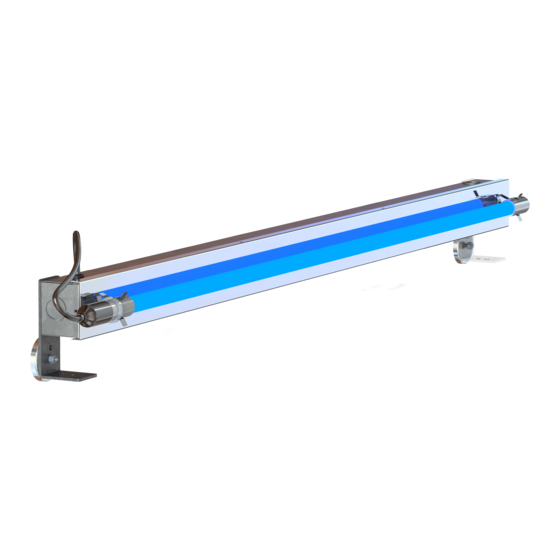
This device is designed to be installed into
a new or existing HVAC system for
improved indoor air quality.
BEFORE INSTALLING
• Read all instructions carefully. Failure
to do so could damage the equipment
or cause harm to yourself or others.
• Acknowledge all warnings.
• Only qualified technicians should
perform the installation.
Installation & Operation Manual
This manual covers the following models:
120V
XL 21"
#06170
XL 33"
#06172
XL 45"
#06174
XL 61"
#06176
BIO-FIGHTER
230V
277V
#06178
#06171
#06179
#06173
#06188
#06175
#06189
#06177
INCLUDED INSIDE BOX
• Bio-Fighter
®
XL UV light system
• UV-C lamp
• Magnetic mounting brackets
• Mounting hardware
• Installation instructions
XL
®
212006-00 Rev. 5A 09/21
Advertisement
Table of Contents

Summary of Contents for Dust Free Biofighter XL 21
- Page 1 BIO-FIGHTER ® Installation & Operation Manual This manual covers the following models: 120V 230V 277V XL 21" #06170 #06178 #06171 XL 33" #06172 #06179 #06173 XL 45" #06174 #06188 #06175 XL 61” #06176 #06189 #06177 GENERAL INCLUDED INSIDE BOX This device is designed to be installed into •...
-
Page 2: Specifications
NOTICE Qualified Technicians Only. This device must be installed in compliance with all national and local electrical and mechanical codes. Failure to do so will void Dust Free® Warranty. -
Page 3: Special Installation Notes
BIO-FIGHTER XL INSTALLATION & OPERATION MANUAL ® UNPACKING SPECIAL INSTALLATION NOTES The Bio-Fighter XL is packaged with a Do not install in closet return grille ® clear protective film covering the polished applications. aluminum reflector. This film must be Do not expose wiring or plastic parts to removed prior to operation. - Page 4 BIO-FIGHTER XL INSTALLATION & OPERATION MANUAL ® COIL SIZING REFERENCE INSTALLATION Determine the dimensions of the coils or area to be irradiated. Use the Coil Sizing Reference to determine the number of lamps needed for proper coverage. Larger coils may require multiple Bio- Fighter kits.
- Page 5 BIO-FIGHTER XL INSTALLATION & OPERATION MANUAL ® CONFIGURATIONS Note: The configurations shown represent typical UVC coverage for coil surface disinfection. Adding more lamps is acceptable and is recommended for airborne disinfection. 18" 32" Single 33" Lamp 72" 32" 32" 32" Single 33"...
- Page 6 BIO-FIGHTER XL INSTALLATION & OPERATION MANUAL ® 32" 32" 40" 48" Single 33" Lamp Single 45" Lamp 48" 48" 40" 48" Dual 33" Lamps Dual 45" Lamps 72" 72" 40" 48" Dual 33" Lamps Dual 45" Lamps...
- Page 7 BIO-FIGHTER XL INSTALLATION & OPERATION MANUAL ® 32" 72" Single 61" Lamp 48" 72" Dual 61" Lamps 72" 72" Dual 61" Lamps...
-
Page 8: Installation
BIO-FIGHTER XL INSTALLATION & OPERATION MANUAL ® INSTALLATION Remove the lamp from the fixture and remove the cover. Multiple mounting methods may be used depending on installation and desired orientation. Slotted Uni-strut channel (13/16") is commonly used to mount the unit. (Not included.) STRUT MOUNT Attach brackets to the Bio-Fighter XL first. -
Page 9: Direct Mount
BIO-FIGHTER XL INSTALLATION & OPERATION MANUAL ® DIRECT MOUNT Remove the lamp from the fixture and remove the cover. Mounting holes are pre-cut in each fixture making installation a bolt-on procedure using sheet metal screws or proper mounting hardware Fig. 5 Direct mount installation allows unit to be depending on installation. -
Page 10: Connecting To Power
BIO-FIGHTER XL INSTALLATION & OPERATION MANUAL ® CONNECTING TO POWER With cover removed, use a screwdriver to remove one of the unit knockouts. Locate the ends of the wires and push through this hole. Connect the black and white wires to proper power and the green wire to ground. -
Page 11: Troubleshooting
UV-C lamp, in the same container you Device fails to operate. received your replacement, to: 1. Check proper power is being supplied Dust Free® Reclamation to the device, and that the lamp lights 1112 Industrial Drive when unit is turned on. -
Page 12: Warranty
PRODUCT. (Some states do not allow the exclusion or limitation of incidental or consequential damages, so this limitation may not apply to you.) THE WARRANTIES SET FORTH HEREIN ARE EXCLUSIVE AND DUST FREE, LP EXPRESSLY DISCLAIMS ALL OTHER WARRANTIES, WHETHER WRITTEN OR ORAL, IMPLIED OR STATUTORY, INCLUDING BUT NOT LIMITED TO ANY WARRANTIES OF MERCHANTABILITY, WORKMANSHIP , OR FITNESS FOR A PARTICULAR USE.
Need help?
Do you have a question about the Biofighter XL 21 and is the answer not in the manual?
Questions and answers