Table of Contents
Advertisement
Advertisement
Table of Contents

Related Manuals for Schmitz OPX mobilis Series


Summary of Contents for Schmitz OPX mobilis Series
- Page 1 Service manual Operating table OPX mobilis and OPX mobilis RC...
- Page 2 This service manual contains instructions how to carry out repairs on the mobile operating tables – OPX mobilis 200 – OPX mobilis 300 C – OPX mobilis 300 CL – OPX mobilis 300 CE – OPX mobilis 300 CLE – OPX mobilis RC30 –...
-
Page 3: Table Of Contents
Contents Introduction ................5 About this service manual . - Page 4 Contents Table base ............... . . 47 Replacing the batteries .
-
Page 5: Introduction
Schmitz u. Söhne. This service manual contains instructions how to carry out In addition to this service manual and the obligatory... -
Page 6: Symbols Used In The Text
Introduction Symbols used in the text In this service manual following designations or signs are used for pieces of information of special importance Danger! This symbol will appear wherever safety hints This symbol will appear in front of additional are designed to protect people from physical helpful pieces of advice. -
Page 7: Safety Instructions
Safety instructions The operating table OPX mobilis has been constructed Always keep the operating manual at hand at the site of according to the latest state of engineering and according use of the operating table! to the acknowledged rules of safety engineering. Nevertheless, its use may inflict danger to life or physical Additionally to the operating manual, observe the safety of the user or of third parties, or impairment to the... - Page 8 Introduction Service manual...
-
Page 9: Description Of The Operating Table
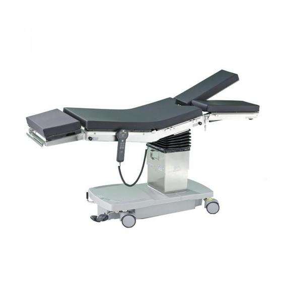
Description of the operating table Head section Back section Seat section Leg plate Battery charger for electric version Foot pump lever Pedal for brake and for directional castor Swivelling lever Potential equalization socket Control panel for Swivel-type castor electric version In the following service manual the terms left, right, front, All operating table models are mobile. - Page 10 Description of the operating table All operating table models are equipped with According to the regulations of the European Standard mechanically operated hydraulic pumps. The operating 60601-2-46 the operating tables are designed to carry a tables of the model series 200 have got two hydraulic maximum patient weight of 135kg.
-
Page 11: Repairs
Preparations Repairs Preparations Removing and re-attaching the cladding panels The bellows is attached to the upper cladding panel by Detaching the cladding panels means of screws and expanding arbours. In order to remove the cladding panels, the bellows has to be The cladding panels consist of two parts, which are detached first from the upper cladding panel. - Page 12 Repairs • Loosen two fastening screws each at the left and right into the connecting strips. Fix the cladding panels to hand side of one section of the cladding panels. the frame by means of the fastening screws. • Loosen the upper and lower cladding panel from the •...
-
Page 13: Removing And Re-Attaching The Cladding Of The Mobile Base
Preparations Removing and re-attaching the cladding of the mobile base Removing the cladding of the mobile base Now repairs on the table base can be carried out. When the repairs have been finished, the cladding has to be The cladding of the mobile base can be removed. In placed back onto the mobile base. -
Page 14: Replacing Or Lowering The Floor Pan
Repairs Replacing or lowering the floor pan For some kinds of repairs, the floor pan has to be Removing or lowering the floor pan removed. The floor pan is fixed to the mobile base by • Loosen the two fastening screws at the front and the means of two screws each at the sides and two additional screws at the front. -
Page 15: Detaching And Re-Attaching The Table-Top
Preparations Detaching and re-attaching the table-top For some kinds of repairs, the table-top has to be plastic cladding which is fixed to the cheeks by means of detached. The table-top is fixed to a holding plate on top expansion rivets. of the height adjustment column. - Page 16 Repairs • For operating table models RC 30 with kidney bridge: Loosen the screw joint at the T-piece. Close the T-piece immediately afterwards. • Then loosen the clamping sheet for the T-piece. The hydraulic systems of the upper section and of the lower section are now separated.
-
Page 17: Height Adjustment Column
Height adjustment column Height adjustment column Filling new hydraulic cylinders with hydraulic fluid and installing them New hydraulic cylinders together with their check valves carefully into the piston rod end of the cylinder. As as well as the hydraulic hoses have to be filled with soon as hydraulic fluid emerges from the loose screw hydraulic fluid upon installation. -
Page 18: Aerating The Lateral And Trendelenburg Adjustment Cylinders And The Check Valves
Repairs De-aerating the lateral and Trendelenburg adjustment cylinders and the check valves If the table-top is unstable after replacement of the lateral hydraulic fluid carefully into the piston end of the or Trendelenburg adjustment cylinder, we recommend to cylinder. As soon as hydraulic fluid emerges from the proceed as follows in order to attain optimal stability. -
Page 19: Replacing The Check Valve And The Hydraulic Cylinder For Lateral Adjustment
Height adjustment column Replacing the check valve and the hydraulic cylinder for lateral adjustment All operating tables can be adjusted by means of Installing the check valve at the hydraulic cylinder for hydraulic cylinders. The hydraulic cylinders are equipped lateral adjustment with check valves. - Page 20 Repairs • In order to detach the hydraulic cylinder from the Removing the hydraulic cylinder for lateral adjustment lower bearing, loosen the locking screw, screw the The rod of the hydraulic cylinder for lateral adjustment is lower fastening screw out, remove the washer connected to the table-top.
- Page 21 Height adjustment column Installing the hydraulic cylinder for lateral adjustment Attention! Mind the exact guiding of the hydraulic hoses, and especially the position of the laces at the hoses and at the cables. The initial state has to be exactly restored. If an important loss of hydraulic fluid has occurred during assembly or replacement of a hydraulic cylinder, hydraulic fluid has to be...
-
Page 22: Replacing Check Valves And Hydraulic Cylinder For Trendelenburg Adjustment
Repairs Replacing check valves and hydraulic cylinder for Trendelenburg adjustment All operating tables can be adjusted by means of Installing the check valve at the hydraulic cylinder for hydraulic cylinders. The hydraulic cylinders are equipped Trendelenburg adjustment with check valves. Hydraulic cylinders and check valves can be replaced. - Page 23 Height adjustment column Removing the hydraulic cylinder for Trendelenburg Installing the hydraulic cylinder for Trendelenburg adjustment adjustment • Install the new hydraulic cylinder. You will find details The piston rod of the hydraulic cylinder is connected to the table-top. A bolt is driven through the fork rest on top of in the chapters “Filling new hydraulic cylinders with the piston of the hydraulic cylinder and through the hydraulic fluid and installing them”...
-
Page 24: Sealing Or Replacing The Hydraulic Cylinder For Height Adjustment
Repairs Sealing or replacing the hydraulic cylinder for height adjustment The operating tables can be adjusted in height by means Sealing the hydraulic cylinder for height adjustment of a hydraulic cylinder. The hydraulic cylinder for height adjustment can be sealed. Preparation Circlip •... - Page 25 Height adjustment column Replacing the hydraulic cylinder details under “Adjusting the guidings of the height adjustment column” on page 27. • Position the table onto assembly jigs. • Remove the floor pan. You will find details under Attention! “Replacing or lowering the floor pan” on page 14. •...
-
Page 26: Sensors In The Mobilis Rc
Repairs Sensors in the mobilis RC The sensors for 0 position in the RC table models are Checking the functions of the sensors positioned next to the cylinders for Trendelenburg and for lateral adjustment. The sensor for height adjustment is The functional state of the sensors or of the terminal box positioned below the lateral adjustment cylinder. -
Page 27: Adjusting The Guidings At The Height Adjustment Column
Height adjustment column Adjusting the guidings at the height adjustment column All operating table models are adjustable in height by means of the height adjustment column with hydraulic lift. Threaded bolt The inner telescopic column is guided by means of plastic (if applicable) screws installed at both sides. - Page 28 Repairs • In order to adjust the guiding of the inner column, Adjusting the guidings of the ball bearings loosen the locknut at one of the rear ball bearings. The inner column is guided by means of four ball bearings each at the front and at the rear. The ball Attention! bearings at the rear are eccentric.
-
Page 29: Folding The Back Section On Top Of The Seat Section
Table-top Table-top Folding the back section on top of the seat section • Fold the back section on top of the seat section and The back section of the table has to be folded on top of the seat section in order to carry out repairs at the upper carry out the repairs. -
Page 30: Replacing The Latches At The Seat And Back Sections
Repairs Replacing the latches at the seat and back sections Head plate and leg plate are locked by means of latches. The threaded bolts are secured by means of The locking mechanism can be replaced. screw locking varnish. They have probably to be heated before they can be unscrewed. -
Page 31: Replacing The Gas Springs At The Back Section And Repairing The Release Mechanism
Table-top Replacing the gas springs at the back section and repairing the release mechanism The back section of the OPX mobilis 200, mobilis 300 Preparation and mobilis RC 30 operating table models can be • Fold the back section on top of the seat section. You adjusted against the counterpressure of two gas springs. - Page 32 Repairs • Loosen the headless screws above the bearing bolts at Replacing the hydraulic system the inner side of the back section frame. The bearing bolts are now accessible. The hydraulic system for releasing the gas springs consists • Start the upper and lower bearing bolts from the back of a hydraulic cylinder with a hydraulic hose leading to a section frame using the drift bolt.
- Page 33 Table-top Attention! Adjusting the level of hydraulic fluid inside the It is important not to have air entrapped inside hydraulic system the system. As long as the system is opened the hydraulic cylinder must in no case be activated. When the hydraulic system has been opened, it has to be Top up emerged hydraulic fluid immediately topped up with hydraulic fluid afterwards.
- Page 34 Repairs Screwing the compressor on Final tasks • Screw the compressor back on top of the piston rod (if • Check the function of the gas springs and of the required, secure it by means of screw locking varnish), hydraulic release mechanism when the back section is push the casing over the hydraulic cylinder and insert charged with approx.
-
Page 35: Replacing The Hydraulic Cylinders For Back Section Adjustment In The Rc40 Model
Table-top Replacing the hydraulic cylinders for back section adjustment in the RC40 model The back section of the RC40 model can be adjusted Removing the hydraulic cylinder electro-hydraulically. The hydraulic cylinders are installed in the LH and RH frame of the back section. The hydraulic cylinders are fixed to the frame by means of bearing bolts. - Page 36 Repairs • Go on pumping carefully until the air has been Filling new hydraulic cylinders with oil and de-aerating them discharged from the piston rod end and through the loosened screw joints. Retighten the loosened screw The two new hydraulic cylinders for back section joints.
-
Page 37: Replacing The Piloted Check Valve For Back Section Adjustment In The Rc40 Model
Table-top Replacing the piloted check valve for back section adjustment in the RC40 model The RC40 table model features a back section with electrohydraulic adjustment function. The piloted check valve is installed below the seat section pad, under the plastic cover of the top of the height adjustment column. Preparation •... -
Page 38: Longitudinal Displacement Function
Repairs Longitudinal displacement function The operating tables can be equipped with a longitudinal displacement function of the table-top. In that case the mounting of the seat section at the covering plate of the height adjustment column is not rigid but moving. There are holders with an arbour at both cheeks of the seat section. -
Page 39: Detaching One Side Of The Table-Top From And Re-Attaching It To The Column
Longitudinal displacement function Detaching one side of the table-top from and re-attaching it to the column Most kinds of repairs on the longitudinal adjustment The fastening screws are secured by means of mechanism can be carried out with the table-top screw locking varnish. -
Page 40: Replacing The Stop Panel
Repairs Replacing the stop panel In its initial state the longitudinal displacement function is Installing the stop panel locked by means of the teeth of a stop panel interlocking • In order to install a new stop panel, position the with those of a rack. -
Page 41: Replacing The Rack
Longitudinal displacement function Replacing the rack The longitudinal displacement function is locked in its initial state by means of the teeth of a stop panel interlocking with those of a rack. The racks can be replaced. The racks are fixed to the underside of the bearing tubes. They are accessible from the left or right hand side of the operating table. -
Page 42: Repairing The Relay Arm For The Stop Panel
Repairs Repairing the relay arm for the stop panel Preparation Feed hose Compressor of the • Remove the arbour on the respective side of the actuating cylinder operating table. You will find details in the chapter Spacer “Detaching and re-attaching one side of the table- Compressor of the return top”... -
Page 43: Repairing The Release Mechanism For Longitudinal Adjustment Function
Longitudinal displacement function Repairing the release mechanism for longitudinal adjustment function Preparation Repairing the hydraulic system • Fold the back section on top of the seat section. You The release system of the longitudinal displacement will find details in the chapter “Folding the back function consists of three hydraulic cylinders which are section on top of the seat section”... - Page 44 Repairs Replacing the input cylinder in the back section The input cylinder in the back section is installed the same way as the input cylinder of the gas spring release mechanism, however, it is installed into the left hand back section frame.
- Page 45 Longitudinal displacement function Attention! Replacing the actuating cylinder Hydraulic hoses will not work properly if there The actuating cylinders are installed at the seat section are kinks inside. Make sure to install the hoses together with the relay arms and the return springs. in such as way as to avoid their being kinked or squeezed.
-
Page 46: Replacing The Bearing Bushes And The Sliding Strips
Repairs Replacing the bearing bushes and the sliding strips Preparation Replacing the bearing bushes • Detach the corresponding side of the table-top. You will find details in the chapter “Detaching and re- The bearing bushes are secured by means of attaching one side of the table-top”... -
Page 47: Replacing The Batteries
Table base Table base Replacing the batteries • Before replacing the batteries, switch the electro- The operating table models with an “E” in their type designation as well as the “RC” models are equipped with hydraulic pump off at the main switch. •... -
Page 48: Replacing The Reed Board (Not In The Rc Models)
Repairs Replacing the reed board (not in the RC models) Operating table models with an “E” in their type Removing the reed board designation are equipped with an electrically-driven hydraulic pump. These operating tables are also Return hose Circlip equipped with a hand-held control unit indicating the Threaded bolt with preselected adjustment function by means of LEDs. - Page 49 Table base Installing a reed board switch can be diminished by turning the headless screw Installation of a new reed board is carried out in reverse order. Headless screw • Insert the two plug-type connectors and screw the fastening screws in. •...
-
Page 50: Piloted Check Valve For Height Adjustment Cylinder
Repairs Piloted check valve for height adjustment cylinder All operating tables are equipped with a piloted check Removing and installing the check valve for the height valve for the height adjustment cylinder. There are three adjustment cylinder hydraulic connections in the model types mobilis 200 to mobilis 300 and four hydraulic connections in the RC models. -
Page 51: Removing And Re-Installing The Control Box Of Mobilis 300 E Tables
Table base Removing and re-installing the control box of mobilis 300 E tables The operating table models with an “E” in their type Removing the control box designation are equipped with an electrically driven hydraulic pump. These operating tables are also The control box is fixed to the side of the floor pan by equipped with a control box with a socket for the means of four screws. - Page 52 Repairs Installing a control box Assignment of the cables on the terminal strips A new control box can be installed in reverse order. • Push the control box from the front through the cut-out white in the floor pan. brown •...
-
Page 53: Removing And Re-Installing The Control Box Of The Mobilis Rc Tables
Table base Removing and re-installing the control box of the mobilis RC tables The RC operating table models are controlled by a Installing the control box control box. The control box is equipped with fuses which can be replaced if required (see operating manual). A new control box can be installed in reverse order. -
Page 54: Adjusting The Directional Castor
Repairs Adjusting the directional castor • In order to detach the clevis, loosen the locknut of the The operating tables with a “C” in their type designation are equipped with an add-on directional castor. The clevis, detach the circlip of the bolt and pull the bolt directional castor can be adjusted. -
Page 55: Adjusting The Dead Centre Of The Pedal For The Brake And For The Directional Castor
Table base Adjusting the dead centre of the pedal for the brake and for the directional castor In order to adjust the top dead centre of the pedal for the Screwing the adjusting screw in will facilitate loosening brake and for the directional castor, turn the adjusting the brake, while screwing the adjusting screw out will screw. -
Page 56: Replacing The Hydraulic Switch Valve
Repairs Replacing the hydraulic switch valve All operating table models can be adjusted hydraulically. They can be adjusted by means of either the foot pump or the electro-hydraulic pump. The individual adjustment functions are preselected by means of a hydraulic switch valve. - Page 57 Table base • Pull the switch valve out. • Then use the foot pump to pump hydraulic fluid through the switch valve until the air has escaped from the first screw joint. • Tighten the first screw joint. The first hydraulic Installing a hydraulic switch valve chamber is now de-aerated.
-
Page 58: Replacing Double Castors
Repairs Replacing double castors The operating tables are equipped with four electrically Installing the double castors conductive double castors. The double castors can be replaced. The locking direction of the new double castor is indicated by means of a sticker. Install the new double castor in mid-position and the direction of locking pointing away Preparation from the pedal end of the table. -
Page 59: Replacing The Electro-Hydraulic Pump
Table base Replacing the electro-hydraulic pump • In order to remove the electro-hydraulic pump, switch Operating tables with an “E” in their type designation are equipped with an electrically-driven hydraulic pump. The the main switch OFF, detach the electric connections at electro-hydraulic pump can be replaced if required. - Page 60 Repairs Service manual...
-
Page 61: Electrical Safety
Table base Electrical safety After the repairs, the design-related and functional features essential for the safety of the appliance must be checked, insofar as they may be affected by the repairs. After modifications which may alter the safety characteristics of the appliance, the corresponding check- ups of the resistance of the protective conductor and of the equivalent of the leakage current have to be carried out. -
Page 62: Carrying Out The Measurements
Electrical safety Carrying out the measurements The appliances have to be connected to the measuring has to be determined, if possible before any repair is units according to the measurements to be carried out carried out. This value has to be recorded in writing as a and according to the circuit diagrams. -
Page 63: Visual Inspection
Table base Visual inspection Before the following tests concerning the protective their mobility, and all supporting parts, for possible measures against an excessive shock hazard voltage can damage. In the evaluation of the safety status of be carried out, repaired or modified appliances must be appliances, it should particularly be taken care, that visually checked for externally or internally recognizable –... -
Page 64: Measuring The Resistance Of The Protective Conductor
Electrical safety Measuring the resistance of the protective conductor A current of a minimum of 5 A and of a maximum of 25 A Hard-wired appliances flows from a power supply with an off-load voltage of a maximum of 6 V to the protective conductor section which For hard-wired appliances, the resistance between the is to be measured. -
Page 65: Measuring The Equivalent Of The Leakage Current To Ground
Table base Measuring the equivalent of the leakage current to ground Measuring the leakage current on site is either impossible Measuring circuit or requires special effort. Normally, the measurement of the equivalent of the leakage current is sufficient after The measuring circuit consists of the actual measuring repairs to and modifications of appliances connected to device and an external circuitry. - Page 66 Electrical safety Appliances with mains cable The pins of the mains plug, which are temporarily connected to be conductive (except earthing pin plugs), as well as accessible metal parts of the enclosure are connected with the measuring device according to the following diagram.
- Page 67 Table base Designation of the appliance: Type/production number: Inventory number: Signature of the Testing authority Name Date Kind of testing Results inspector Initially measured value Repeated measurements Operating table OPX mobilis and OPX mobilis RC – E DITION 05-03-GB ID.-Nr.: 02008857...
- Page 68 Electrical safety Designation of the appliance: Type/production number: Inventory number: Signature of the Testing authority Name Date Kind of testing Results inspector Service manual...
- Page 69 Table base Operating table OPX mobilis and OPX mobilis RC – E DITION 05-03-GB ID.-Nr.: 02008857...
-
Page 70: Technical Data
Technical data Technical data Measurements/weights/electrical data OPX mobilis RC30 RC30L RC40 300 C 300 CL 300 CE 300 CLE RC30/G RC30L/G RC40/G Total length w/o 1,780mm head plate Total length incl. 2,130mm head plate Width of table-top 540mm Total width 590mm Floor plate 1,022mm ×... - Page 71 Fine-wire fuses 5 × 20mm: — battery charger 2 pcs 0.4A, slow-blow type / 1 pc 2.0A, slow-blow type Schmitz u. Söhne GmbH & Co. KG P . O. Box 1461, D-58734 Wickede (Ruhr) Zum Ostenfeld 29, D-58739 Wickede (Ruhr) Germany...
-
Page 72: Block Diagram Electric System
Technical data Block diagram electric system Service manual... -
Page 73: Block Diagram Hydraulic System
Table base Block diagram hydraulic system Operating table OPX mobilis and OPX mobilis RC – E DITION 05-03-GB ID.-Nr.: 02008857... -
Page 74: Overview Electric System Mobilis 300 E
Technical data Overview electric system mobilis 300 E Service manual... -
Page 75: Overview Electric System Mobilis Rc30/40
Table base Overview electric system mobilis RC30/40 Operating table OPX mobilis and OPX mobilis RC – E DITION 05-03-GB ID.-Nr.: 02008857... -
Page 76: Cabling Of The Valves Mobilis Rc30
Technical data Cabling of the valves mobilis RC30 Service manual... -
Page 77: Cabling Of The Valves Mobilis Rc40
Table base Cabling of the valves mobilis RC40 Operating table OPX mobilis and OPX mobilis RC – E DITION 05-03-GB ID.-Nr.: 02008857... -
Page 78: Cabling Of The Sensors Mobilis Rc30/40
Technical data Cabling of the sensors mobilis RC30/40 Service manual... -
Page 79: Hydraulic Diagram Mobilis 200 To 300E
Table base Hydraulic diagram mobilis 200 to 300E Operating table OPX mobilis and OPX mobilis RC – E DITION 05-03-GB ID.-Nr.: 02008857... -
Page 80: Hydraulic Diagram Mobilis Rc30
Technical data Hydraulic diagram mobilis RC30 Service manual... -
Page 81: Hydraulic Diagram Mobilis Rc40
Table base Hydraulic diagram mobilis RC40 Operating table OPX mobilis and OPX mobilis RC – E DITION 05-03-GB ID.-Nr.: 02008857... -
Page 82: Hydraulic Diagram Mobilis Kidney Bridge
Technical data Hydraulic diagram mobilis kidney bridge Service manual... -
Page 83: Spare Parts
Spare parts Technical descriptions such as circuit diagrams, exploded views, repair instructions or spare parts lists can be obtained upon request from Schmitz u. Söhne. When ordering technical descriptions or spare parts at the manufacturer’s, kindly indicate the reference no., the serial no. -
Page 84: After Sales Service
Customer service phone +49 (2377) 84549 Phone 02383 - 910 0110 Schmitz u. Söhne GmbH & Co. KG Postfach 1461, D-58734 Wickede (Ruhr) Zum Ostenfeld 29, D-58739 Wickede (Ruhr) Germany Phone +49 (2377) 840 +49 (2377) 84162 http://www.schmitz-soehne.de e-mail: export@schmitz-soehne.de...
Need help?
Do you have a question about the OPX mobilis Series and is the answer not in the manual?
Questions and answers