Table of Contents

Related Manuals for TRW TA S40 Series

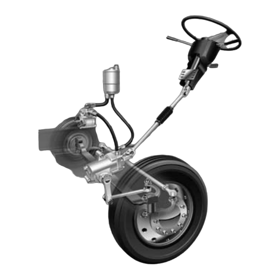
Summary of Contents for TRW TA S40 Series
- Page 1 GROUP 0603-V-003-0207 STEERING 0603-V-003-0207 TRW TAS STEERING GEAR TRW Automotive Commercial Steering Systems TAS Steering Gear Service Manual T A S40,55,65, 66 AND 85 SERIES DocID TRW TAS STEERING GEAR Page 1-1 Review Draft...
- Page 2 Service Manual and warranty. Do not try to repair or service a TAS steering gear which has been damaged or includes any part that shows excessive wear unless the damaged and worn parts are replaced with original TRW replacement and service parts and the unit is restored to TRW's specifications for the TAS steering gear.
-
Page 3: Table Of Contents
All steering mechanisms are safety critical items. As such, it is imperative that the instructions in this booklet be followed to the letter. Failure to observe the procedures set forth in this manual may result in a loss of steering. DocID TRW TAS STEERING GEAR Page 1-3 Review Draft... -
Page 4: General Information
Exploded View Part Descriptions ............. 13 Service Parts List ..................14 Parts Vary by Specification ............... 15 Service Kits (General) ................16 Service Kits (Gear Specific) ..............16 Page 1-4 TRW TAS STEERING GEAR DocID File Last Modified: September 17, 2012 10:18 am... - Page 5 GROUP 0603-V-003-0207 STEERING DocID TRW TAS STEERING GEAR Page 1-5 Review Draft...
-
Page 6: Introduction
STEERING GROUP 0603-V-003-0207 Introduction This new TAS Service Manual replaces all previous editions of TRW's TAS40, 55, 65, 66 and 85 Service Manuals. Changes in the layout of this Service Manual reflect TRW's commitment to provide easily usable material and highly recognizable hazard notices. Some of the major changes are: replace damaged parts and return to the resealing procedures easily. - Page 7 GROUP 0603-V-003-0207 STEERING DocID TRW TAS STEERING GEAR Page 1-7 Review Draft...
-
Page 8: Oil Flow Illustration
Right Hand Turn Steering Wheel Input: Clockwise Rotation Straightline Running No Steering Action Left Hand Turn Steering Wheel Input: Counter-Clockwise Rotation Supply Pressure Return Pressure Page 1-8 TRW TAS STEERING GEAR DocID File Last Modified: September 17, 2012 10:18 am... -
Page 9: General Design
As the driver turns the steering wheel faster or slower, more or less fluid will be required by the gear. TAS series vehicle front-end weight ratings are as follows: DocID TRW TAS STEERING GEAR Page 1-9 Review Draft... -
Page 10: General Operation
The procedures for Flushing and Air Bleeding the System are found in cylinder bore. The rack piston then turns the sector shaft to steer the the Steering Maintenance Guideline packet (TRW Document #800). vehicle. Replacement of damaged automatic bleed plugs, and manual bleed screws is described on page 52. -
Page 11: Gear Specification Numbers
A - Q = Step Bore Hsg. Date Code Serial # T - Z = High Flow Poppets R = Reman (TRW) Date Code An example date code would be 29097; this means the gear was built on the 290th day of 1997. -
Page 12: Torque Chart
⁄ ⁄ of a turn as described in step 23 on page 47. Warren, MI 48092 1-800-328-6657 ** Torque value indicated is using recommended tools. Page 1-12 TRW TAS STEERING GEAR DocID File Last Modified: September 17, 2012 10:18 am... -
Page 13: Exploded View
STEERING Exploded View TAS40, 55, 65 and 66 TAS85 Only Short "V" Rack Piston Assembly Long "V" Rack Piston Assembly Standard Step Bore w/ Retaining Ring Step Bore w/ Hook Groove DocID TRW TAS STEERING GEAR Page 1-13 Review Draft... -
Page 14: Exploded View Part Descriptions
Seal, Dirt and Water ∇ Poppet Adjusting Screw Kit ♣♥ Seal, Dirt and Water Bleed Screw, Manual Bleed Screw, Auto Plug, Auxiliary Port (Side Cover) Page 1-14 TRW TAS STEERING GEAR DocID File Last Modified: September 17, 2012 10:18 am... -
Page 15: Service Parts List
Available in Kit Screw, Manual Bleed 213705 213705 213705 (Housing Location Not Shown) Screw, Auto Bleed 021397 021397 021397 (Housing Location Not Shown) Plug, Auxiliary Port (Side Cover Location) 415437-A1 415437-A1 415437-A1 DocID TRW TAS STEERING GEAR Page 1-15 Review Draft... -
Page 16: Parts Vary By Specification
Guide Halves, Ball Return Piston, Rack Housing Shaft, Sector Cover Assembly, Side Bolts, Side Cover (6 or 8) Bearing, Roller *Contact TRW Technical Service for part numbers Page 1-16 TRW TAS STEERING GEAR DocID File Last Modified: September 17, 2012 10:18 am... -
Page 17: Service Kits
Poppet Kit TAS000004 TAS65095T TAS65126T TAS65142T TAS65198T TAS65200T TAS65202T TAS65213T TAS65214T TAS65215T TAS66006T TAS40019A Poppet Adjusting Screw/Nut Kit 021318X1 TAS40030A TAS40044A TAS65006A TAS65013A TAS65033A TAS65035A TAS65076A TAS65133A TAS66005A TAS65033A TAS85055A TAS85064A TAS85067A DocID TRW TAS STEERING GEAR Page 1-17 Review Draft... -
Page 18: Installation
STEERING GROUP 0603-V-003-0207 Section 2 Installation Page 1-18 TRW TAS STEERING GEAR DocID File Last Modified: September 17, 2012 10:18 am... -
Page 19: Initial Installation
Full turn in one direction Full turn in other direction DocID TRW TAS STEERING GEAR Page 1-19 Review Draft... -
Page 20: Maintenance Tips
Make sure the steering column is aligned properly. Encourage drivers to report any malfunctions or accidents Do not attempt to weld any broken steering component. Page 1-20 TRW TAS STEERING GEAR DocID File Last Modified: September 17, 2012 10:18 am... -
Page 21: Output Shaft Grease Pack Diagrams
GROUP 0603-V-003-0207 STEERING Output Shaft Grease Pack Diagrams Step Bore with Hook Groove Gear Step Bore Gear Standard Gear DocID TRW TAS STEERING GEAR Page 1-21 Review Draft... -
Page 22: Gear Disassembly, Inspection And Assembly
Roller Bearing - Standard Gears ........... 50 Roller Bearing - Step Bore Gears ..........51 Port Plugs, Screws and Grease Fitting Replacement ....... 52 Final Adjustments ..................53 Page 1-22 TRW TAS STEERING GEAR DocID File Last Modified: September 17, 2012 10:18 am... - Page 23 GROUP 0603-V-003-0207 STEERING DocID TRW TAS STEERING GEAR Page 1-23 Review Draft...
-
Page 24: Disassembly Preparation
The steering gear should be identified to the vehicle from which it was removed. The poppet adjuster seat and sleeve assem- blies are set for that particular vehicle only. Page 1-24 TRW TAS STEERING GEAR DocID File Last Modified: September 17, 2012 10:18 am... -
Page 25: Disassembly Procedures
This will position the sector shaft for removal. Remove dirt & Standard gears only - Remove and discard dirt & water seal water seal (52) from the housing trunnion. Small screwdriver DocID TRW TAS STEERING GEAR Page 1-25 Review Draft... - Page 26 You may start the shaft and cover assembly removal by tapping the end of the Soft mallet shaft lightly with a soft mallet or wooden hammer handle. Page 1-26 TRW TAS STEERING GEAR DocID File Last Modified: September 17, 2012 10:18 am...
- Page 27 Inspect the sector shaft assembly for damaged adjusting screw screw and retainer threads. The retainer must be securely staked in place. The adjusting screw must rotate by hand with no perceptible end play (lash). DocID TRW TAS STEERING GEAR Page 1-27 Review Draft...
- Page 28 The set position of poppet seat and sleeve assemblies (23) must not be disturbed if the poppets are not going to be replaced or reset during disassembly. Page 1-28 TRW TAS STEERING GEAR DocID File Last Modified: September 17, 2012 10:18 am...
- Page 29 Screwdriver Left hand ball return guide halves are copper or zinc chromate plated for identification and right hand guides are not plated. RETAIN THE GUIDES FOR REASSEMBLY. DocID TRW TAS STEERING GEAR Page 1-29 Review Draft...
- Page 30 Poppets section on page 41. Otherwise, proceed to step 27. TRW recommends the poppet seat and sleeve assemblies (23) not be removed unless replacement of poppet components is required.
- Page 31 Auxiliary port plugs (8) and o-rings (9) If any are damaged, go to Replace Housing Ports, Plugs, Screws, Fittings on page 52. If not, proceed to the Inspection Section on page 31. DocID TRW TAS STEERING GEAR Page 1-31 Review Draft...
-
Page 32: Inspection
Inspect the rack piston ball track grooves for brinelling or and worm ball spalling. If either condition exists, replace the input shaft, track grooves valve/worm assembly, valve housing, rack piston subassembly and balls. Page 1-32 TRW TAS STEERING GEAR DocID File Last Modified: September 17, 2012 10:18 am... - Page 33 Remove masking tape from the shaft and inspect for twisted or otherwise damaged serrations. If any of these conditions exist, replace the sector shaft. A service sector shaft will come assembled with the adjusting screw and retainer. DocID TRW TAS STEERING GEAR Page 1-33 Review Draft...
-
Page 34: Assembly Preparation
Replace all seals, seal rings, and gaskets with new ones each time you disassemble the gear. TRW Commercial Steering Systems has complete seal kits available. These kits can be purchased through most OEM parts distributors. Contact your local dealer for availability. - Page 35 TAS40, 55, 65, 66: Oil new seal ring (11) and assemble in valve housing mounting face groove. TAS85: Oil new seal ring (11) and assemble in valve housing pilot groove. *Trademark of Exxon Oil Corp. DocID TRW TAS STEERING GEAR Page 1-35 Review Draft...
- Page 36 Use the correct quantity of service balls: TAS40-29, TAS55-31, TAS65- 32, TAS66-32 TAS85-34, when using the service ball kit. Page 1-36 TRW TAS STEERING GEAR DocID File Last Modified: September 17, 2012 10:18 am...
- Page 37 Torx socket Ft lb Torque wrench Ball cap seal is greased to hold Grease seal in groove while assembling. Be sure not to trap the seal outside of the groove during reassembly. DocID TRW TAS STEERING GEAR Page 1-37 Review Draft...
- Page 38 80 ft lb (108.5 N m). Torque TAS85 bolts to 118 ft lb (160 N m). E-16 Torx socket (TAS40, 55, 65, 66) E-18 Torx socket (TAS85) Ft lb Torque wrench Page 1-38 TRW TAS STEERING GEAR DocID File Last Modified: September 17, 2012 10:18 am...
- Page 39 Screwdriver Rotate the adjusting screw clockwise one half turn so the side cover will rotate freely on the sector shaft. *Trademark of Exxon Oil Corp. DocID TRW TAS STEERING GEAR Page 1-39 Review Draft...
- Page 40 Masking tape If the serrations are not properly taped, they will damage the output seal (43) in housing, causing the seal to leak. Page 1-40 TRW TAS STEERING GEAR DocID File Last Modified: September 17, 2012 10:18 am...
- Page 41 This step may have already been completed if you disassembled the valve housing and worm screw for repair. Proceed to Final Adjustments on page 53. *Trademark of Exxon Oil Corp. DocID TRW TAS STEERING GEAR Page 1-41 Review Draft...
-
Page 42: Poppets
Poppet Spacer Rod Poppet Seat Poppet Seat Poppet Seat and Poppet Seat and Poppet Poppet Sleeve Assembly Sleeve Assembly Push Tube Push Tube Sleeve Sleeve Page 1-42 TRW TAS STEERING GEAR DocID File Last Modified: September 17, 2012 10:18 am... - Page 43 (24), and the other new poppet adjuster seat and sleeve assembly (23). The new components will stack up as shown J36452-A below. Ft lb Torque wrench Torque both poppet seat and sleeve assemblies to 18 lbf ft (25 N m). DocID TRW TAS STEERING GEAR Page 1-43 Review Draft...
-
Page 44: Valve Housing/Worm Screw
Turn bearing adjuster locknut (22) out of the valve housing. adjuster locknut J37464 Remove bearing Turn bearing adjuster (21) out of the valve housing. adjuster J37070 Page 1-44 TRW TAS STEERING GEAR DocID File Last Modified: September 17, 2012 10:18 am... - Page 45 Remove seal rings Remove and discard seal rings and o-rings (11, 12, 13, 14, 15, and o-rings 16) from valve housing (10). Small probe or pick DocID TRW TAS STEERING GEAR Page 1-45 Review Draft...
- Page 46 Do not clamp against threaded port hole or relief valve hole sealing faces when placing valve housing in vise. Page 1-46 TRW TAS STEERING GEAR DocID File Last Modified: September 17, 2012 10:18 am...
- Page 47 Install seal ring Lightly oil and assemble new seal ring (14) onto input shaft and against the thick thrust washer (17) to hold the bearing components in place. DocID TRW TAS STEERING GEAR Page 1-47 Review Draft...
- Page 48 Lightly oil and assemble new locknut (22) onto bearing adjuster locknut (21) with radius (slightly rounded) side down. Tighten slightly to keep the bearing adjuster in place. J37464 Page 1-48 TRW TAS STEERING GEAR DocID File Last Modified: September 17, 2012 10:18 am...
- Page 49 Unstake and readjust if necessary. wrench Reposition subas- Reposition worm screw/valve housing subassembly in soft- sembly in vise jawed vise, clamping tightly against valve housing, so the worm screw is pointing down. DocID TRW TAS STEERING GEAR Page 1-49 Review Draft...
- Page 50 (2) and install it over the input shaft. Seat the seal in Grease the groove behind the serrations and against the valve housing. *Trademark of Exxon Oil Corp. Page 1-50 TRW TAS STEERING GEAR DocID File Last Modified: September 17, 2012 10:18 am...
-
Page 51: Roller Bearing - Standard Gears
(short end). If the bearing Press removal end of the bearing & seal tool is used to press in bearing, the cage on the new bearing may be damaged. DocID TRW TAS STEERING GEAR Page 1-51 Review Draft... -
Page 52: Roller Bearing - Step Bore Gears
If the unmachined trunnion face is not square, use shims to square it before pressing in the bearing. Page 1-52 TRW TAS STEERING GEAR DocID File Last Modified: September 17, 2012 10:18 am... -
Page 53: Port Plugs, Screws And Manual Bleed Screw Replacement
" Some gears may be equipped with In lb Torque manual or auto bleed screws and/or wrench auxiliary port plugs in the side cover. See page 12 exploded view for illustration. DocID TRW TAS STEERING GEAR Page 1-53 Review Draft... -
Page 54: Final Adjustments
(180°) each side of center. In lb Torque wrench Screwdriver ⁄ Socket " Page 1-54 TRW TAS STEERING GEAR DocID File Last Modified: September 17, 2012 10:18 am... - Page 55 N m) and check input shaft, valve/worm assembly torque again. ⁄ Socket " Readjust if input shaft torque exceeds 40 in lb (4.5 N m). Ft lb Torque wrench In lb Torque wrench DocID TRW TAS STEERING GEAR Page 1-55 Review Draft...
-
Page 56: Reinstallation
STEERING GROUP 0603-V-003-0207 Section 4 Reinstallation Page 1-56 TRW TAS STEERING GEAR DocID File Last Modified: September 17, 2012 10:18 am... - Page 57 GROUP 0603-V-003-0207 STEERING DocID TRW TAS STEERING GEAR Page 1-57 Review Draft...
-
Page 58: Reinstallation Procedure
STEERING GROUP 0603-V-003-0207 Reinstallation Procedure Poppet Resetting Procedure Page 1-58 TRW TAS STEERING GEAR DocID File Last Modified: September 17, 2012 10:18 am... -
Page 59: Glossary
Systems Impact Rotary Control Valve Axial Internal Leakage Scoring Brinelling Lash Shock Load Date Code Manual Bleed Systems Spalling Discoloration Subassembly OSHA External Leakage Supply Line Poppets Full Turn Twisted Serrations DocID TRW TAS STEERING GEAR Page 1-59 Review Draft... - Page 60 GROUP 0603-V-003-0207 TRW Automotive Commercial Steering Systems 800 Heath Street Lafayette, IN 47904 Tel 765.423.5377 Fax 765.429.1868 www.trucksteering.com © TRW Inc. 2007 TRW1108 Rev. 2/07 Page 1-60 TRW TAS STEERING GEAR DocID File Last Modified: September 17, 2012 10:18 am...
Need help?
Do you have a question about the TA S40 Series and is the answer not in the manual?
Questions and answers