Table of Contents
Advertisement
Quick Links
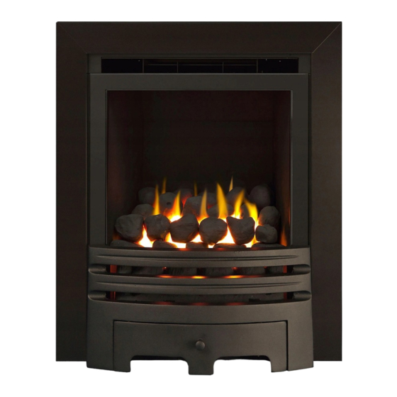
Model
Eco4
MkIII
Design options
Apex, Adjusta, Aleda, Black-Watch, Cristal, Contemporary, Fairfield,
Liberty, Caledonian, Lux, Ignite, Maine, Mystique, Pinnacle, Sirius
Westerly, Verto
Installation and User Instructions
All instructions must be handed to
user for safekeeping
This is not a DIY product and must be
installed by a Gas Safe registered
installer
Edition D 05/17
Country(s) of destination - GB/IE
Please ensure you read both the Fire and the Fascia instructions before starting the
installation.
1
Advertisement
Table of Contents

Subscribe to Our Youtube Channel
Related Manuals for Sirocco Eco4 MKIII

Summary of Contents for Sirocco Eco4 MKIII
- Page 1 Model Eco4 MkIII Design options Apex, Adjusta, Aleda, Black-Watch, Cristal, Contemporary, Fairfield, Liberty, Caledonian, Lux, Ignite, Maine, Mystique, Pinnacle, Sirius Westerly, Verto Installation and User Instructions All instructions must be handed to user for safekeeping This is not a DIY product and must be installed by a Gas Safe registered installer Edition D 05/17...
- Page 2 INSTALLATION INSTRUCTIONS These Notes Must Be Read Before Installation This appliance is an Inset Live Fuel Effect appliance that provides radiant or combined radiant and convected heat; it cannot and should not be used as the main heating source within a property.
-
Page 3: Table Of Contents
CONTENT CHECK LIST Quantity Description Firebox and Burner Tray Decorative Trim/Frame Fire Fret/Front Fuel Bed Cable fixing kit; 1 cable, 1 tensioner, 1 cable clamps, 3 fixing eyes. Lengths of adhesive sealing strip. Set of manufacturer’s instructions and warranty card. Raw Plugs INSTRUCTIONS CONTENT Section... -
Page 4: Important Notes
Section 1: IMPORTANT NOTES This fire is an Inset Live Fuel Effect Gas Fire providing radiant warmth. It is designed to operate on Natural Gas or LPG. It is the LAW that all gas appliances and fittings are installed by a competent person such as a Gas Safe Registered fitter and in accordance with the Gas Safety (Installation and Use) Regulations 1998, the relevant British Standards for Installation, Codes of Practice and in accordance with the manufacturers’... - Page 5 Section 2: INSTALLATION REQUIREMENT This appliance MUST NOT be installed into a bathroom or shower room, or where steam may be present. An extractor fan must not be fitted in the same room or space as the appliance as this can affect the safety of the appliance.
- Page 6 Section 3: APPLIANCE INFORMATION Eco4.3 Hotbox Convector Gas Group G20 Natural Gas CAT I2H G20 Natural Gas CAT I2H Inlet Pressure 20 mbar 20 mbar Max Input (gross) Min Input (gross) Setting Pressure 20 mbar 20 mbar Gas Inlet 8mm Compression 8mm Compression connection Overall Height...
-
Page 7: Ventilation
SECTION 4: VENTILATION This Appliance does not normally require purpose provided ventilation. However, a second appliance operating within the same room or space must be taken into consideration when assessing ventilation. When commissioning the appliance spillage is detected, then amongst other problems there may be insufficient natural ventilation for correct operation of the flue. - Page 8 The current versions of BS1289 and BS EN 1806 recommend that there should be an air space or insulation between the flue blocks and the plaster because heat transfer may cause cracking on directly plastered flues. However, generally this appliance is suitable for installations under all circumstances unless there is a history of cracking problems, remember that faults such as cracking may be caused by poorly built and restrictive flues, e.g.
- Page 9 Eco 4 Height 552-575mm Width 350-455mm Depth 113mmHotbox / 134mm Convector Minimum Hearth Depth in Front of the Fire 300mm Heath must Extend Minimum of 150mm Minimum Hearth Height 50mm Hole-in-the-wall installations Where the appliance is to be installed as a hole-in-the-wall fireplace, a hearth as previously detailed for floor level fireplaces shall be fitted on the floor beneath the hole so as to protect combustible material from heat.
-
Page 10: Debris Space
The manufacturers’ instructions for fitting the prefabricated box must be complied with at all times. To fit the fire using the cable fixing kit supplied, some minor adaption may be necessary for certain flue boxes. Please ensure the firebox does not obscure the flue box outlet. The firebox, base of the flue box, and hearth below may be drilled to allow plugs and screws to secure installation. - Page 11 Diagram 3 ISOLATION SCREWS On the slide control option disassemble the linkage by removing the two screws (shown in diagram below), to the slide control then remove the burner from the assembly by removing the three screws at the base of the burner tray and undoing the connecting nut to the isolation tap on the side.
- Page 12 The tray is now free and may be lifted away from the box, lift free of the retaining clips or screws on each side of the burner tray. Carefully remove the spark generator from the box or remove the cables to the generator, making a note of which cable goes where.
-
Page 13: Preparing The Opening
SECTION 7.1: PREPARING THE OPENING Before installing the fire, check the flue for correct operation using a smoke pellet, all of the smoke should be drawn up the flue and exit correctly from the terminal. If problems are found DO NOT fit the fire until corrective measures have been completed. Protect the decorative hearth whilst pushing the convector box in and out of the opening. - Page 14 If the fireplace does not allow for the exact layout shown, the eyebolts should be fixed to give a similar configuration as possible. Thread the tensioning cable through the holes at the top of the firebox, then through the two screw eyes in the top position and then through the one at the lower position, back through the lower hole in the firebox as shown in the diagram.
- Page 15 Thread the cable tensioner onto the cable as shown, with the nuts screwed down close to the tensioner head, slide the screwed nipple through the box and pull cable taut and tighten pinch screw on to the cable. Pinch screw Tension nut Adjust tensioner using a suitable spanner to pull the cable tight into position, to allow an even seal around the edge of the fire, visually inspect the seal and reseat if necessary.
-
Page 16: Fitting The Burner Tray
SECTION 7.2 FITTING THE BURNER TRAY Temporarily fit the burner tray and ensure a suitable gas route can be achieved. If the fire is the manual control system, you can now place the burner tray into the firebox making sure that the side lugs locate properly on to the side of the firebox. Fit the two securing screws through the front plate ensuring that the plate is in front of the front edge of the fire box. -
Page 17: Fuel Bed
Please note the position on the securing bracket and ensure this is not fixed upside down which will cause the fire not to work. SECTION 8: FUEL BED LAYOUT Place the ceramic rear matrix onto the burner ensuring that the rear matrix is sitting behind the two fixed brackets, the back of the matrix rests against the back panel fitted at the rear or the box. - Page 18 Place front matrix coal support into brackets fitted BURNER PILOT ASSEMBLY FRONT MATRIX Note: Please ensure that there is a gap between the back of the front matrix and the pilot assembly where applicable, this is to ensure correct operating of the pilot and O.D.S system, this must not be touching the assembly as this will cause the fire to operate incorrectly and cause damage to the fire and to malfunction.
- Page 19 Place the front row of 5 coals/pebbles between the front coal support and the rear matrix as shown. Now Place the second row as shown below, coals may be rotated slightly within their positions to give a good visual effect.
- Page 20 Note: The coals must not be crammed together, or inserted into the holes in the matrix, a well lay out; generously spaced coal layout will give the best results. Pay special attention to finally adjust the coals with the fire lit on the HIGH setting in order to ensure that no flames play onto the firebox sides.
- Page 21 Place the Random Coal Front matrix in place, insuring that it does not touch the pilot assembly behind. Place two B Coals at each end of the front matrix and the rear matrix as shown do not block the area between the coal supports. Place the three coals A as shown again ensuring that the area between the coal supports is clear.
- Page 22 The fire front/fret shown in these instructions may differ from the one supplied with the appliance, we strongly recommend you use a fire front/fret supplied by Sirocco fires as these products will have been tested with the appliance, although other fire front/frets will be...
-
Page 23: Commissioning The Appliance
Section 10: COMMISSIONING THE APPLIANCE Turn on and test the gas supply up to the fire for any leaks, in accordance with current Approved Codes of Practice (ACOPs) Section 10.1: OPERATING THE APPLIANCE (See User Instructions Section 18) Section 10.2: SPARK FAILURE The gap between the spark electrode and the pilot should be 3.5 - 4.5mm to produce a good spark. -
Page 24: Setting Pressure
SECTION 11: SETTING PRESSURE Remove the pressure test point sealing screw from the isolation elbow and attach a suitable pressure gauge. Check that the inlet gas pressure is at 20 mbar Working Pressure at 20 Mbar (+/- 1 mbar) Light the pilot and check the correct operation of the burner at all the flame settings. Refer to the Operating instructions section 10.1 Check that the inlet gas pressure is at 20 mbar (+/- 1 mbar), when the fire is at its highest setting. -
Page 25: Testing For Spillage
SECTION 12: FLUE SPILLAGE MONITORING SYSTEM Slide controlled fires are fitted with a flue spillage safety device (ODS). If the fire shuts down during use for no apparent reason then several things may be suspected, if a door or window has been opened creating a draught, then pilot disturbance is the problem, and removal of the draught should resolve this. - Page 26 First bend the spigot plate provided to approximately 70° The flue spigot restrictor is fixed into place with two screws from the front of the fire SCREWS Please Note: If using the Super Convector firebox and the spillage test fails please remove the spigot restrictor making sure to replace the screws back in to their positions and re-test.
-
Page 27: Briefing The Customer
SECTION 14: BRIEFING THE CUSTOMER • All instructions must be handed to the user for safekeeping. • Show the customer how to light and operate the fire. • After commissioning the appliance, the customer should be instructed on the safe use of the appliance and the informed for the need of regular servicing. -
Page 28: Cleaning The Coals
SECTION 16: CLEANING THE COALS • Remove the fire front/fret casting and place to one side. • Remove the ceramic components. • Gently clean in the open air using a dry paint brush. • Be careful not to create dust from the coals. •... -
Page 29: User Instructions
SECTION 18: USER INSTRUCTIONS IMPORTANT NOTES The installation of this fire MUST only be carried out by a competent person (such as a Gas Safe registered fitter) in accordance with the Gas Safety (Installation and Use) Regulations 1998, the relevant British Standards, Codes of Practice, the Building Regulations and the manufacturers’... - Page 30 OPERATING THE APPLIANCE (Manual Control) For your safety, the fire is fitted with a Flame Supervision Device (FSD), which will shut off the Gas supply if for any reason the pilot is extinguished. This device incorporates a fixed probe, which senses heat from the pilot burner flame, if the probe is cooled, the device will prevent any gas flow.
- Page 31 OPERATING THE APPLIANCE (Slide control) For your safety, the fire is fitted with a Flame Supervision Device (FSD), which will shut off the Gas supply if for any reason the pilot is extinguished. Fit the 9V battery in to the battery lead at the left-hand side of the fire. This device incorporates a fixed probe, which senses heat from the pilot burner flame, if the probe is cooled, the device will prevent any gas flow.
- Page 32 CLEANING • Before carrying out any of the following operations, ensure that the fire is OFF and completely cold. • Debris that may form on the fire bed should be periodically removed by a competent person. • Large deposits could indicate deterioration of the flue. This should be repaired by a competent person, and the fire serviced before further use.
- Page 33 BEFORE CONTACTING SIROCCO FOR SERVICE PLEASE READ THE FOLLOWING; Sirocco is committed to customer care and service. To ensure we provide the best service we can we have a policy to charge for all none warranty home visits so that all customers with a genuine manufactures fault can be dealt with swiftly, if your appliance has recently been installed and you are experiencing any of the following;...
-
Page 34: List Of Spares
SECTION 20: LIST OF SPARES Eco 4 Manual Control 13/14B 7B/8B 9B/10B... - Page 35 Eco 4 Slide Control...
- Page 36 Eco4 Ceramics...
- Page 37 Eco4 Ceramics...
- Page 38 Code SPARE PART DESCRIPTION PARTNUMBER FRONT MATRIX E4 REAR MATRIX E4 black 2-BLK COAL SET E4 (9 PCS) COAL SET RANDOM (9 PCS) PEBBLE SET E4 (granite grey 9 pc) BACK BOARD ECO 4 SPARK ELECTRODE INC FIXING SCREW THERMOCOUPLE INC LOCK NUT ISOLATION/PRESURE TEST POINT VALVE INC NUT &...
-
Page 39: Contact Details
Purchase spare parts direct from our website www.siroccofires.com Spare parts are managed by our UK partner company Lodestar-Delta Ltd Lodestar-Delta Ltd T/A Sirocco Unit 1, 11 Weir St, Blackburn, Lancashire BB2 2AN SIROCCO HEAD OFFICE Telephone number for all departments 0843 289 4268 (charged at BT national rate) - Page 40 5 year warranty Contacting Sirocco If you need to contact Sirocco for a Warranty service or to purchase spare parts the contact details and procedure are printed on the back page of your installation/user guide...
- Page 41 No other validation will be accepted by Sirocco. Accidental damage or improper use is not covered by warranty. This guarantee is non-transferable and is made to the original owner provided that the purchase was made through an approved Sirocco Fires stockist...
- Page 42 COMPLETE THE FORM USING CAPITALS DATE OF PURCHASE AS IT APPEARS ON YOUR RECEIPT SERIAL NUMBER (WHICH IS SHOWN ON THE DATA BADGE OF THE APPLIANCE) MR MRS MISS INITIALS. SURNAME HOUSE NUMBER ADDRESS TEL NUMBER POST CODE EMAIL ADDRESS WHERE YOU PURCHASED YOUR APPLIANCE FROM NAME ADDRESS...
- Page 43 SIROCCO Sp. Zo. o PLEASE AFFIX C/O UNIT 1 STAMP THE WEIRS HERE 11 WEIR STREET BLACKBURN LANCASHIRE, BB2 2AN FOLD HERE...
Need help?
Do you have a question about the Eco4 MKIII and is the answer not in the manual?
Questions and answers