Table of Contents
Advertisement
Quick Links
Advertisement
Table of Contents

Related Manuals for Spacelabs Healthcare elance 5

Summary of Contents for Spacelabs Healthcare elance 5
- Page 1 Vital Signs Monitor 93300 Operations Manual 070-1963-00 Rev. M...
- Page 2 the equipment is used in accordance with the operations manual. Spacelabs Healthcare will make available, on request, such circuit diagrams, or component part lists, descriptions, calibrating instructions or other information which will assist appropriately qualified technical personnel to repair those parts of the equipment which are classified by Spacelabs Healthcare as field repairable.
-
Page 3: Table Of Contents
Table of Contents Contents Page élance Vital Signs Monitor .....................1-1 Intended Use .......................... 1-1 Indications for Use........................1-2 Equipment Classification ......................1-2 Product Configurations......................1-3 Features ..........................1-4 1.5.1 Physical and Mechanical .................... 1-4 1.5.2 Electrical........................1-4 1.5.3 Display ........................1-4 1.5.4 Touchscreen Keys ...................... - Page 4 Table of Contents Trends Management.......................5-1 View and Print Tabular Trends....................5-1 5.1.1 View Tabular Trends at user-selectable period............5-3 View and Print Graphical Trends.................... 5-4 Managing Alarms......................6-1 Alarm Limits..........................6-2 6.1.1 Default Alarm Activation and Limits Setting..............6-2 6.1.2 Numerical Area Alarm Activation and Limits Setting ..........6-3 Silence Alarm Mode .......................
- Page 5 Table of Contents 11.1 Activating/Deactivating EtCO Waveform ................11-1 11.2 EtCO2 Zone.......................... 11-3 11.3 Getting into the EtCO2 Setup....................11-4 11.4 Set Waveform Size....................... 11-4 11.5 Set EtCO2 Units ........................11-5 11.6 Set EtCO2 Alarm ........................11-5 11.7 Time to EtCO2 Alarm ......................11-6 12 SpO Monitoring......................12-1 12.1 Physical Setup Connections....................
- Page 6 Table of Contents 15 Temperature Monitoring ....................15-1 15.1 Physical Setup Connections....................15-1 15.2 Temperature Zone........................ 15-1 15.3 Getting into the Temperature Setup..................15-2 15.4 Set Units ..........................15-2 15.5 Set Alarm and Limits ......................15-3 15.6 Time to Temperature Alarm ....................15-3 16 Printing ..........................16-1 16.1 Loading Printer Paper ......................
-
Page 7: Élance Vital Signs Monitor
1 élance Vital Signs Monitor This manual describes the most common features and functions of the élance Vital Signs Monitor. Note: Before use, carefully read this manual, directions for all accessories, all precautionary information and specifications. Intended Use The Spacelabs élance Vital Signs Monitor is used to monitor the following parameters for adult and pediatric patients. -
Page 8: Indications For Use
élance Vital Signs Monitor Indications for Use The élance Vital Signs Monitor is indicated for use in patient populations for: Adult Pediatric The élance Vital Signs Monitor facilitates the monitoring of: Respiration Non-invasive blood pressures ... -
Page 9: Product Configurations
élance Vital Signs Monitor Product Configurations The élance Vital Signs Monitor 93300 may be configured with the following options: Configuration Model Options Description 10.2” display with Basic configuration, 4 93300 waveforms élance ECG, SpO , NIBP, respiration, dual temperature 10.2” display with ECG, SpO , NIBP, 93300 -05I... -
Page 10: Features
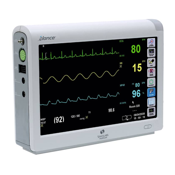
élance Vital Signs Monitor Features 1.5.1 Physical and Mechanical The élance Vital Signs Monitor is a lightweight, integrated vital signs monitor with a 10.2-inch or 12.1-inch wide-screen color thin-film-transistor (TFT) liquid crystal display (LCD) using a resistive touchscreen. Different parameter configurations provide vital signs monitoring for a large range of acuity. -
Page 11: Touchscreen Keys
élance Vital Signs Monitor 1.5.4 Touchscreen Keys The élance Vital Signs Monitor uses touchscreen to execute monitoring functions. Refer to the chapter on Using the Monitor for more information. 1.5.5 Auxiliary Outputs The élance Vital Signs Monitor provides remote nurse alert, printing via serial communication port, keyboard/mouse interface and software update via USB port. - Page 12 Use only accessories approved by Spacelabs healthcare. For a list of approved supplies and accessories, refer to the élance Vital Signs Monitor Supplies and Accessories data sheet (P/N 061-2193-00). Other cables, batteries, transducers and accessories may cause a safety hazard.
-
Page 13: Cautions
élance Vital Signs Monitor Alarms Alarms may be delayed in certain circumstances. See time to alarm sections in individual parameter chapters. Alarm conditions for which you want to be alerted must be set to ON or enabled. To protect the patient’s safety, do not silence, suspend, or disable audible alarms without providing continuous, direct observation of the patient. - Page 14 − Refer to the EMC Appendix to the Service Manual − Consult the élance Vital Signs Monitor Service Manual (P/N 070-1949-00) or your Spacelabs Healthcare Service Representative for help. There may be situation where other bedside device/fixture may generate electrical interference when there is grounding issue, thus causing ECG artifact at the monitor as it is in the closest proximity of patient.
-
Page 15: Introduction To The Monitor
2 Introduction to the Monitor This chapter introduces the élance Vital Signs Monitor including all external connections, display symbols, and colors used on the display to indicate the different functions and messages. The monitor also provides an external interface to support an alarm relay connection. -
Page 16: Side Views
Introduction to the Monitor Side Views élance Vital Signs Monitor external connections are located on the right side of the monitor. NIBP IBP1 (optional) IBP2 (optional) (optional) élance Vital Signs Monitor left side view ... -
Page 17: External Connector Symbols
Introduction to the Monitor 2.1.1 External Connector Symbols Symbol Description Symbol Description Power Button Date of Manufacture Universal Serial Bus Network Connector ECG Connector Alarm Relay Connection Attention, Consult Accompanying IBP Connector Documents Degree of Protection from Liquid Spacelabs SpO Connector Ingress Masimo SpO... -
Page 18: Software Interface
Introduction to the Monitor Software Interface The élance Vital Signs Monitor shown below is made up of four distinct areas. The Waveform Area The Numerical Area The Patient Information Area The Main Menu Area. 2.2.1 The Waveform Area The élance Vital Signs Monitor has four or five equally sized waveform areas depending on your purchased monitor configuration. -
Page 19: The Numerical Area
Introduction to the Monitor 2.2.2 The Numerical Area The élance Vital Signs Monitor has six or seven numerical reading controls dep ending n options purchased: ECG (HR) IBP2 RR (Respiration) NIBP Temperature IBP1 2.2.3 The Patient Information Area This area displays the patient information. -
Page 20: The Main Menu Area
Introduction to the Monitor 2.2.4 The Main Menu Area The Main Menu enables you to perform specific functions of the élance Vital Signs onitor. The Main Menu has the following keys: E NUMERIC – Display param eters in large numeri c display. -
Page 21: Monitor Display Symbols
Introduction to the Monitor 2.2.5 Monitor Display Symbols Symbol Description Symbol Description Electrocardiogram (ECG) End Tidal Carbon Dioxide EtCO2 Waveform Waveform ECG Size Scale of 1mV Inspired CO2 FiCO2 mmHG/ ECG Lead II EtCO Unit : mmHg/kPa Lead II Pulse Oximetry Waveform Respiration Pulse Oximetry % Respiration Rate/min... -
Page 22: Colors
Introduction to the Monitor 2.2.6 Colors The default c olors and rela ted functions of t he élance Vital Signs Monitor are shown in table below. Function Color ECG and HR Green EtCO White Respiration Yellow and R Cyan NIBP and PR White Blue Blue... -
Page 23: Monitor Controls
Introduction to the Monitor Monitor Controls Except for powering ON the monitor, you control the élance Vital Signs Monitor through the to uchscreen (Lit up areas shown below): Main Menu erical Area The touch screen main menu icons are located along the right side of the screen. They are always visible and each key performs a specific function regardless of the parameter being monitored. -
Page 24: Setup Menu
Introduction to the Monitor 2.3.1 Setup Menu The Setup Menu enables you to define healthcare monitoring settings to the élance Vital Signs Monitor. The Setup Menu appears when you touch the Monitor Setup key as indicated above. - Suspends all alarms - Admit/Edit patient information, discharge a patient - Set alarms On/Off, Low Limit and High Limit - Set the var... -
Page 25: Main Menu Control Windows
Introduction to the Monitor 2.3.2 Main Menu C ontrol Windows Trends Display 2.3.3 Numerical Area Control Windows Setup ECG Control Setup RR Control Setup SpO Control Setup IBP Control élance Vital Signs Monitor Operations Manual Page 2-11... -
Page 26: Standby Mode
Introduction to the Monitor Setup ETCO2 Control NIBP Control Setup Temperature Control 2.3.4 Standby Mode When the élance Vital Signs Monitor is set on Standby Mode, all monitoring arameters are temporarily suspended until user manually resumes its monitoring. élance Vital Signs Monitor Operations Manual Page 2-12... -
Page 27: External Interface
Introduction to the Monitor xternal Interface The élance Vital Signs Monitor provides external connectors on the right side and rear panel of the monitor to support communication with external device and functions. An external recorder can be attached to the right. 2.4.1 Alarm Relay Connection Warning: Do not use the alarm relay connection as the primary source of alarm... -
Page 28: Using The Monitor
3 Using the Monitor Warning: Keep patients under close surveillance when monitoring. It is possible that radiated electromagnetic signals from sources external to the patient and the élance Vital Signs Monitor can cause inaccurate measurement readings. Do not rely entirely on the élance Vital Signs Monitor readings for patient assessment. -
Page 29: General Monitor Settings
Using the Monitor Caution: If an error occurs, do not use the élance Vital Signs Monitor. Contact qualified service personnel or your Spacelabs healthcare Service Representative. eral Monitor Settings re are various settings for the élance Vital Signs Monitor to be set. - Page 30 Using the Monitor 4. Touch the Set Date and Time key. A Set Date and Time window, as shown below, will appear. 5. Touch the Year keys to set the current year as required. 6. Touch the Month keys to set the current month as required. 7.
-
Page 31: Set Date And Time Format
Using the Monitor Caution: The date and time cannot be set from the bedside monitor if the monitor is connected to the élance Central Station. The Central Station date and time information will be applied to the bedside monitor. 3.2.2 Set D ate and Time Format The date and time display format can be set by user. -
Page 32: Save User Defaults
Using the Monitor 5. Touch the Date Format key. A dropdown list, as shown below, will appear. 6. Touch the desired date format from the dropdown list.. 7. Touch OK key to confirm or Cancel key to quit. The monitor date and time will be displayed in selected format at the lower right of the screen. - Page 33 Using the Monitor ouch the Save User Defaults key. A Save User Defaults window, as shown below, will appear. 5. Touch the OK key to save the current monitor setup as the user defaults. 6. Touc h the Cancel key to quit if required. élance Vital Signs Monitor Operations Manual Page 3-6...
-
Page 34: Restore User Defaults
Using the Monitor 3.2.4 Restore User Defaults The saved user defaults can be restored as the monitor setup. TEPS 1. Touch the Monitor Setup key located on the right side of the screen. A Setup menu will appear. Touch the Clinical from the Setup menu. A Setup Clinical window will appear. Touch the System key. -
Page 35: Waveform Settings
Using the Monitor 5. Touch the OK key to restore the saved user defaults as the monitor setup. 6. Touch the Cancel key to quit if required. Note: The user default saved in the élance Vital Signs Monito r will be applied to new patients automatically when a new patient is connected to this monitor. -
Page 36: Set Waveform Source
Using the Monitor 3.3.1 Set Waveform Source You can set the source of all the waveforms from this control. TEPS 1. Touch the Monitor Setup icon from the Main Menu. A Setup menu will appear. 2. Touch the Waveforms fr om the Setup menu. -
Page 37: Set Waveform Size
Using the Monitor 3.3.2 Set Waveform Size You can set the size of all the waveforms from this control. TEPS 1. Touch the Monitor Setup icon from the Main Menu. A Setup menu will appear. 2. Touch the Waveforms from the Setup menu. A Setup Waveforms window will appear. -
Page 38: Set Waveform Numbers
Using the Monitor 3.3.4 Set Waveform Numb Waveform numbers displayed on screen can be set by user in this control. The vailable number selections are equal to or less than the configured waveform umbers of purchased option. TEPS Touch the Monitor Setup icon from the Main Menu. A Setup menu will appear. Touch t he Waveforms from the Setup menu. -
Page 39: Set Waveform And Parameter Color
Using the Monitor Touch the required number. Touch OK key to confirm or Cancel key to quit. 3.3.6 Set Waveform and Parameter Color Color of waveforms and parameters can be user-configured from this control. TEPS 1. Touch the Monitor Setup icon from the Main Menu. A Set p menu will appear. 2. -
Page 40: Display On Large Numeric Screen
Using the Monitor 4. Touch the Set Waveform and Parameter Color key. The following window will appear. 5. Touch the desired Color Key to pick the color. 6. Touch the target Parameter key to change th e color. 7. Repeat step 5 to 6 to set parameter colo 8. - Page 41 Using the Monitor Note: Refer to Chapter 2.2.5 Monitor Display Symbols for the meaning of displayed symbols. 2. To return to normal screen, touch the Large Nu meric icon or Normal Screen icon from the main menu. élance Vital Signs Monitor Operations Manual Page 3-14...
-
Page 42: Patient Management
4 Patient Management This chapter discusses how the patient information can be managed from the élance Vital Signs Monitor. Patient management allows: Admit a new patient Edit patient’s information Discharging a patient Admit/Edit Patient Information The patient’s information in the élance Vital Signs Monitor provides some basic information about the patient. - Page 43 Patient Management 3. Touch Admit key. An Admit window as shown below will appear. 4. Touch OK key to confirm. A Patient Info Edit window as shown below will appear. élance Vital Signs Monitor Operations Manual Page 4-2...
- Page 44 Patient Management r touch Cancel key to go back to Admit/Discharge window and touch Edit key The Patient Info Edit window will appear 6. Touch Display Name key. A Display Name window as shown below, will appear. 7. Enter the patient’s name via the screen keyboard. 8.
- Page 45 Patient Management 11. Touch Year key. A Year window as shown below will appear. 12. Enter the year via the screen keyboard. 13. Touch the OK key to confirm. 14. Repeat steps 11 to 13 to complete the date. 15 Touch Sex dropdown list to select the right one.
-
Page 46: Discharge The Patient
Patient Management 17. Following step 6 to 15 to fill in all the other information. 18. Touch the OK key to confirm. Discharge the Patient Warning: Once you discharge the patient from the élance Vital Signs Monitor, all the patient information and trends will be removed. When a patient is discharged, the patient’s details should also be discharged from the élance Vital Signs Monitor. - Page 47 Patient Management 4. Touch OK key to confirm the discharge of patient or touch Cancel key to quit.. élance Vital Signs Monitor Operations Manual Page 4-6...
-
Page 48: Trends Management
5 Trends Management The élance Vital Signs Monitor enables you to view trend data. Patient trend data is stored for up to 120 hours in non-volatile memory. When the élance Vital Signs Monitor is switched on, the data is stored in the trend memory once every minute or at defined intervals. - Page 49 Trends Management . Touch the Trend Sample Interval key. A dropdown list, as shown below, will appear Note: The interval is set in minute. The default is the last Interval setting. 3. Touch the desired interval. 4. Touch the keys to scroll up and down the list as required. ouch the PgUp or PgDn key to scroll to the previous or next page respectively.
-
Page 50: View Tabular Trends At User-Selectable Period
Trends Management 5.1.1 View Tabular Trends at user-selectable period. You can choose to track trends at any specific period by setting the starting time. Note: This function facilitates historical trends viewing by setting the starting time instead of multiple page scrolling. Caution: This trend view is limited to trend data that are stored in the monitor memory. -
Page 51: View And Print Graphical Trends
Trends Management View and Print Graphical Trends. raphical trends in the élance Vital Signs Monitor can be tracked and printed at cified intervals. Step 1. T ouch the Trends icon from the Main Menu. A Trends window will appear. 2. Touch the Graph key. A graphical Trends window shown as below will appear. Note: The trends and their parameter labels have the same color and bold style. - Page 52 Trends Management 7. To configure the parameters in the trend view, Touch the Setup key. A Setup window as shown below will appear. 8. Touch the parameter selection key. A dropdown shown as below will appear. 9. Touch the desired parameter. 10.
-
Page 53: Managing Alarms
6 Managing Alarms Warning: The Respiration low rate alarm may be delayed up to 60 seconds when there is a complete cessation in breathing by the patient. Do not use this monitor as an apnea monitor. Check the alarm limits to ensure that they are appropriate for the patient being monitored. -
Page 54: Alarm Limits
Managing Alarms LOW priority or technical alarm indicates a setup problem or faulty sensor. The patient not being fully monitored: the parameter numeric zone and the base of the display re yellow. A single low pitch chime tone is generated once every twenty seconds. en the élance Vital Signs Monitor is in the alarm state, you can either temporarily sile... -
Page 55: Numerical Area Alarm Activation And Limits Setting
Managing Alarms 3. Touch the Alarms key of the required parameter to change. A dropdown list, as shown below, will appear. 4. Touch the requir ed Alarm Selection. 5. Touch the Low L keys to increase or decrease the value. imit . - Page 56 Managing Alarms 3. Touch the required Alarm Selection. 4. Touch the Low Limit keys to increase or decrease the value. 5. Touch the High Limit keys to increase or decrease the value. ouch the OK key to confirm. Note: The alarm limit range will display in the Numeric Area in the event that th e alarm of respective parameter is turned on.
-
Page 57: Silence Alarm Mode
Managing Alarms Silence Alarm Mode When the élance Vital Signs Monitor enters the alarm mode (flashing yellow or red ligh on the screen), you can temporarily silence the alarm based on a user defined period before the alarm is activated again i f the patient’s condition is not rectified. -
Page 58: Set Silence Alarm Time
Managing Alarms 6.2.2 Set Silence Alarm Time When the élance Vital Signs Monitor is in silence alarm mode it will automatically revert to the alarm mode after the set time has elapsed. TEPS . Touc h the Monitor Setup icon from the Main Menu. -
Page 59: Alarm Suspend Mode
Managing Alarms Alarm Suspend Mode The élance Vital Signs Monitor allows alarms to be temporarily suspended. 6.3.1 Activate/Deactivate the Suspend Mode The suspend mode is activated and deactivated in the same manner. TEPS 1. Touch the Monitor Setup icon from the Main Menu. A Setup Menu will appear. 2. -
Page 60: Set Alarm Suspend Time
Managing Alarms 6.3.2 Set Alarm Suspend Time When the alarm suspend mode of the élance Vital Signs Monitor is activat ed, it can utomatically revert to the normal mode after a set time. TEPS 1. Touch the Monitor Setup icon from the Main Menu. A Setup men u will appear. -
Page 61: Set Speaker Alarm Volume
Managing Alarms Set Speaker Alarm Volum The speaker alarm volume in the élance Vital Signs Monitor can be set between the range of 1 (softest) and 10 (loudest). TEPS 1. Touch the Monitor Setup icon from the Main Menu. A Setup menu will appear. 2. -
Page 62: Set Pulse Tone Volume
Managing Alarms Set Pulse Tone Volume The pulse tone enables audible tones for each detected beat. When the Pulse Tone Source is SpO , the tone pitch is tied t o the SpO parameter value (higher pitch means igher SpO value). -
Page 63: Activate/Deactivate Spo 2 Alarms Off Message
Managing Alarms Activate/Deactivate SpO Alarms Off Message The élance Vital Signs Monitor displays a message whenever SpO alarms are turned off. You can activate or deactivate it. TEPS . Touch the Monitor Setup icon from the Main Menu. A Setup menu will appear. 2. -
Page 64: Alarm Validation
Managing Alarms Alarm Validation he Alarm Validation function is intended to reduce nuisance alarms in which parameter alues may exceed the alarm limits for a very short time. When this function is enabled, certain parameter limit violations are not considered to be in alarm until they have existed for the times listed below: Limit Violation Alarm Validation Time... -
Page 65: Set Additional Alarm Time
Managing Alarms Set Additional Ala rm Time The additional alarm in the élance Vital Signs Monitor enhances the alarm tone functionality by providing a completely independent backup to the monitor's main speaker. Whenever the monitor starts sounding an audible tone for an alarm condition, it starts a timer. -
Page 66: Alarm Conditions
Managing Alarms Alarm Conditions The table s in this section contain lists of all the conditions the élance Vital Signs onitor can detect for each parameter, along with alarm characteristics of the conditions. General Monitor Conditions: Condition Display Alarm Message Priority Value Monitor needs... - Page 67 Managing Alarms HR Conditions: Condition Display Alarm Message Priority Value HR within limits <Number> None None HR < Low Limit <Number> HR lower than Low Limit Medium HR > High Limit <Number> HR higher than High Limit Medium HR Asystole ECG Asystole High HR Ventricu...
- Page 68 Managing Alarms RR Conditions: Condition splay V alue Alarm Message Priority R within limits <N umber> None None R < Low Limit <N umber> RR lower than Low Limit Medium R > High Limit <N umber> RR higher than High Limit Medium R >...
- Page 69 Managing Alarms Conditions: Condition Display Value Alarm Message Priority SpO , within limits <Number> None None SpO < Low Limit <Number> lower than Low Limit Medium SpO > High Limit <Number> SpO higher than High Limit Medium Bad SpO Probe SpO replace sensor Cannot regulate LED intensity...
- Page 70 Managing Alarms NIBP Conditions: Condition Display Value Alarm Message Priority NIBPs within limits <Nu mber> None NIBPs < Low Limit <N umber> Ps lower than Low Limit Medium NIBPs > High Limit <Nu mber> Ps higher than High Limit Medium NIBPm within limits <Number>...
- Page 71 Managing Alarms TEMP Conditions: Condition Display Value Alarm Message Priority TEMP within limits <Number> None None TEMP < Low Limit <Number> TEMP lower than Low Limit Medium TEMP > High Limit <Number> TEMP higher than High Limit Medium Temp > 50 degrees C TEMP out of range Temp <...
-
Page 72: Factory Default Parameter Ranges And Settings
Managing Alarms EtCO2 Conditions: Condition Display Value Alarm Message Priority EtCO within limits <Number> None None EtCO < Low Limit <Number> EtCO lower than Low Limit Medium EtCO > High Limit <Number> EtCO higher than High Limit Medium No Sampling line None connected <Blank>... - Page 73 Managing Alarms Setting Name Default Value Possible Values PR low alarm limit 30-235 BPM NIBPs high alarm limit 150 mmHg 35-250 mm NIBPs low alarm limit 100 m 30-245 mmHg NIBPs alarms on On, Off NIBPd high alarm limit 100 mmHg 15-210 mmHg NIBPd low alarm limit 60 mmHg...
- Page 74 Managing Alarms Setting Name Default Value Possible Values P2s/P2 ARTs/P2 PRSs On, Off alarms on P2m/P2 ARTm/P2 PRS 70 mmHg -10 to 130 mmHg low alarm limit P2m/P2 ARTm/P2 PRSm 130 mmHg 135 to 230 mm high alarm limit P2m/P2 ARTm/P2 PRSm On, Off alarms on P2d/P2 ARTd/P2 PRSd low...
-
Page 75: Alarm System Verification
Managing Alarms Setting Name Default Value Possible Values Waveform Size Auto Auto Sweep Speed 25 mm/sec 6.25 mm/sec, 12.5 mm/sec, 25 mm/sec Ventricular Tach Alarm Limit 60 Abnormals-per-M inute Abnormals-per- Minute ST Alarm On, Off ST Alarm Limit 0.25 - 5m m in steps of 0.25mm ( Single ST ) Pause Alarm Limit... - Page 76 Managing Alarms 3. Attach the SpO senso r to your index finger and wait for the monitor to display a numerical area va lue. 4. Unplug the senso r from nitor. 5. Ch eck the alarm indica tors after 10 sec onds.
-
Page 77: Ecg And Heart Rate Monitoring
7 ECG and Heart Rate Monitoring Warning: Line isolation monitor transients may resemble actual cardiac waveforms and thus inhibit heart rate alarms. Such transients may be minimized by proper electrode and cable placement. The ECG waveform has a delay of 3 seconds. This is important to be aware of when conducting a procedure which requires observation of real-time data to help prevent possible injury. -
Page 78: Physical Setup Connections
ECG and Heart Rate Monitoring Detection of a lead off condition if an electrode is disconnecte d or poorly connected Detection of the presence of pacemaker signals within the ECG waveform area Note: Electromagnetic interference beyond the range guaranteed from the manufacturer's laration may cause the élance Vital Signs Monitor to display an ECG Leads Of alarm. - Page 79 ECG and Heart Rate Monitoring Apply the e lectrode to the patient’s skin as shown below. Electrode Placement Picture, colour-coded guide ote: The placement site for the fifth lead electrode should be at the V2 to V6 lead electrode placeme nt sites.
-
Page 80: Ecg Zone
ECG and Heart Rate Monitoring ECG Zone The ECG zone consists of two areas: The Waveform area The Numerical area an access the ECG setup by touching the ECG Numerical area. Getting into the ECG Setup You need to access into the Setup ECG windo w to... -
Page 81: Set Ecg Lead
ECG and Heart Rate Monitoring 2. Set the required parameters. 3. Touch the OK key to confirm. Set ECG Lead When you attach ECG lead wires, the Lead Select option displays the available ECG lead selections. TEPS 1. Touch the ECG Numerical Area. A Setup ECG window will appear. . -
Page 82: Set Waveform Size
ECG and Heart Rate Monitoring Electrode Differential Electrode Differential Lead Selection (AAMI) (IEC) RA LA RA LL LA LL V (Chest Lead) (RA+LA+LL)/3 Chest (V) (R+L+F)/3 Chest (C) (Lead I - Lead III)/2 (Lead I - Lead III)/2 - (Lead I + Lead III/2) - (Lead I + Lead III/2) (Lead II + Lead III)/2 (Lead II + Lead III)/2... -
Page 83: Set Hr Source
ECG and Heart Rate Monitoring 3. Touch the uired Size Selection 4. Touch the OK key to confirm. Set HR Source You can select heart rate sourc e from non-ECG para meters, namely ART and SpO The élance Vital Signs Monitor pro vides the capability of auto-switching to alternate R source whenever HR from the p rimary source becomes unavailable. -
Page 84: Set Pulse Tone Source
The HR source will be displayed above the hear rate number if the HR source is not from ECG. If you use ART as an alternative HR Source, Spacelabs Healthcare recommends setting up each monitor with only one arterial pressure channel. -
Page 85: Set Hr Alarm
ECG and Heart Rate Monitoring Touch the required selection from the list. Touch OK to confirm. et HR Alarm You can set the alarm activation and alarm limits from élance Vital Signs Monitor. TEPS 1. Touch the ECG Numerical Area. A Setup ECG window will appear. 2. -
Page 86: Relearn
ECG and Heart Rate Monitoring 7.11 Relearn Dominant rhythm can be relearned and established at any time during monitoring. During the relearning phase, all ECG alarms are suspended. Steps: 1. Touch the first ECG Numerical Area at the top of the screen. A Setup ECG window, as shown below, will appear. -
Page 87: St Monitoring
8 ST Monitoring The ST mon itoring can be enabled in the élance Vital Signs Monitor with ST option to monitor and provide ST alarm. Only a clinician can determine the significance of S changes. The ST value is displayed in the ECG Numerical Area of the associated lead. To isplay S T values of all the leads, set up a second ECG waveform to be displayed on the screen. -
Page 88: St Alarm Settings
ST Monitoring 2. Touch the ST Display Enable key. A dropdown list, as shown below, will appear. 3. Select On from the dropdown list to enable the ST display. Note: The only and default ECG filter mode used for ST monitoring is “ST” with frequency range from 0.05 Hz to 40Hz. - Page 89 ST Monitoring 3. Touch the ST Alarm Settings key. A Setup ST Alarms window, as shown below, will appear. 4. Touch the ST Alarm key. A dropdown list, as shown below, will appear. 5. Touch the required selection to turn on or off the ST alarm. 6.
-
Page 90: St Trends
ST Monitoring Note: The allowed value ranges from 0.25mm to 5mm in steps of 0.25mm. 7. Touch OK to confirm. ST Trends The ST trends can be viewed and printed in both tabular and graphical formats when the ST option is enabled. 8.2.1 View and Print Tabular ST Trends Steps:... -
Page 91: View And Print Graphical St Trends
ST Monitoring 2. Touch the ST Trends key. The following ST Trends window will appear. Refer to section 5.1 View and Print Tabular Trends for operation of the trend function keys. the Normal Screen icon from the main menu to retu rn to normal waveform Touch creen. - Page 92 ST Monitoring Note: The time span number here indicates the displayed trend scope in hours. Refer to section 5.2 View and Print Graphical Trends for operation of the trend function keys. Touch the Normal Screen icon from the main menu to return to normal waveform screen.
-
Page 93: Arrhythmia Analysis
9 Arrhythmia Analysis The élance Vital Signs Monitor provides enhanced arrhythmia detection and alarm capability in addition to the standard and basic arrhythmia. The following enhanced arrhythmia analysis is included: Asystole High Rate Violation Low Rate Violation Ventricular Fibrillation ... -
Page 94: Arrhythmia Review
Arrhythmia Analysis 4. Touch the key of the a ssociated arrh ythmia type to turn on or off the alarms. Touch OK t o confirm. rhythmia Review he arrhythmia review fun ctio n provides re view and printing capability of arrhythmia event occurrences. - Page 95 Arrhythmia Analysis 3. Touch the required arrhythmia type key for detail review. A window,, as shown below, will appear. 4. Touch the keys to scroll up and down the list as required. 5. Touc h the PgUp or PgDn key to scroll to the previous or next page respectively. .
-
Page 96: Respiration Monitoring
10 Respiration Monitoring Warning: The Respiration low rate alarm may be delayed up to 60 seconds where there is a complete cessation of breathing by the patient. Do not use this device as an apnea monitor. Keep patients under close surveillance... -
Page 97: Rr Zone
Respiration Monitoring 10.2 RR Zone he RR zone consists of two areas: The Waveform area The Numerical area You can access the RR menu by touching the RR Numerical area. 10.3 et RR Alarm ou need to access into the RR Setup window to make changes to set the alarm activation and alarm limits. -
Page 98: Time To Respiration Alarm
Respiration Monitoring 2. Touch the Alarms On key. A dropdown list, as shown below, will appear. 3. Touch the required Alarm Selection. 4. Touch the Low Limit keys to increase or decrease the value. 5. Touch the High Limit keys to increase or decrease the value. 6. -
Page 99: Etco Monitoring
11 EtCO Monitoring Warning: The élance Vital Signs Monitor does not have an exhaust connector port, hence all sample gases will be exhausted into the room. Caution: Possession or purchase of the élance Vital Signs Monitor with Oridion Microstream Capnography does not convey any express or implied license to use the device with unauthorized consumable CO2 sampling consumable products which would, alone, or in combination with this device, fall within the scope of one or more of the patents relating to this... - Page 100 EtCO Monitoring ouch the System key. A Setup System window as shown below, wiil appear. 4. Touch the ETCO2 Enabled key. A dropdown list, as shown below, will appe 5. Touch the Yes option to activate or No option to deactivate the EtCO Waveform.
-
Page 101: Etco2 Zone
EtCO Monitoring The respiration monitoring is replaced by the EtCO monitoring on the élance Vital Signs Monitor. Warning: The EtCO2 should be reset or restored from user default manually when required after the monitor is discharged from élance Central Station. 11.2 EtCO2 Zone The EtCO... -
Page 102: Getting Into The Etco2 Setup
EtCO Monitoring ou can access the EtCO menu by touching the EtCO Numerical area. 11.3 Getting into the EtCO2 Setup You need to access into the EtCO Setup window to make any setting changes to the EtCO monitoring. TEPS 1. Touch the EtCO as illustrated below by the icon. -
Page 103: Set Etco2 Units
EtCO Monitoring 3. Touch the required Size Selection. 4. Touch the OK key to confirm. 11.5 Set EtC O2 Units You can change the EtCO display units on the élance Vital Signs Monitor. TEPS ouch the EtCO Numerical Area. A Setup EtCO window will appear. -
Page 104: Time To Etco2 Alarm
EtCO Monitoring TEPS 1. Touch the EtCO Numerical Area. A Setup EtCO window will appear. 2. Touch the Alarms On key. A dropdown list, as shown below, will appear. 3. Touch the required Alarm Selection. 4. Touch the Low Lim keys to increase or decrease the value. -
Page 105: Spo 2 Monitoring
240 for all values greater than or equal to 240. Caution: Use only patient sensors specified by Spacelabs healthcare. If you use sensors other than those specified, it may degrade SpO performance and could damage the élance Vital Signs Monitor during defibrillation. - Page 106 Monitoring Note: Because SpO measurements depend upon light from a sensor, excessive ambient light can interfere with the pulse oximeter’s measurements. This pulse oximeter measures functional saturation, which is essentially percentage hemoglobin that transport oxygen (oxyhemoglobin). Pulse oximeters do not detect significant amount of dysfunctional hemoglobins, such...
-
Page 107: Physical Setup Connections
For more information, refer to the instructions that came with th e sensor or contact Spacelabs healthcare. TEPS Select the proper sensor for the patient. 2. Connect the SpO cable to the SpO connector on the left side of the monitor. - Page 108 Monitoring For anemic patients, this condition occurs because patients have decreased arterial oxygen contents. For patients with dysfunctional hemoglobins (that are unable to carry oxygen), this condition occurs because less functional hemoglobin is available to carry oxygen. aution: Hemoglobin levels below 5 g/dl may prevent the élance Vital Signs Monitor from roviding SpO...
-
Page 109: Spo Zone
Monitoring If high ambient light is affecting measurements, ensure that the sensor is properly applied and then cover the application site with an opaque material such as a blanket or towel. Failure to do this may result in inaccurate measurements. -
Page 110: Getting Into The Spo Setup
Monitoring 12.4 Getting into the SpO Setup You need to access into the SpO Setup window to make any setting changes to the monitoring. TEPS 1. Touch the SpO Numerical Area as illustrated below by the icon. A Setup SpO window, as shown below, will appear. -
Page 111: Set Hr Source
Monitoring 12.5 et HR Source There are four HR source to select from. · ECG · SpO · P1 ART · P2 ART TEPS 1. Touch the SpO Numerical Area. A Setup SpO window will appear. 2. Touch the HR Source key. -
Page 112: Set Spo Alarm
Monitoring 12.7 Set SpO Alarm You can set the alarm activation and alarm limits from the setup SpO window. TEPS 1. Touch the S Numerical Area. A Setup SpO window will appear. . Touch the Alarms On key. A dropdown list, as shown below, will appear. 3. - Page 113 Monitoring At Large Numberic screen: Perfusion Index Indicator The shaded area in the Perfusion In dex indicator expands up proportionally to signal strength. No shading corresponds to no detected signal strength or a faulty sensor. élance Vital Signs Monitor Operations Manual Page 12-9...
-
Page 114: Masimo Set (Signal Extraction Technology)
Monitoring 12.8.2 Masimo SET (Signal Extraction Technology) 12.8.2.1 Sensitivity Modes Setting Sensitivity Modes setting allows clinicians to escalate sensitivity mode to meet demand of patient’s physiology. There are three choices for sensitivity: APOD (Adaptive Probe Off Detection), Normal (default), and Maximum. The NORMAL sensitivity setting is recommended for majority of patients. -
Page 115: Fastsat Settings And Data Averaging Settings
Monitoring Note: Setting function is accessible only for Masimo and Advanced SpO Nellcor SpO Touch the Sensitivity Mode key. A dropdown list, as shown below, will appear Touch the required Mode. Touch OK to confirm or Cancel to quit. 12.8.2.2 FastSat Settings and Data Averaging Settings FastSat setting enables rapid tracking of arterial oxygen saturation changes. -
Page 116: Signal Iq(Siq)
Monitoring Touch the required setting. Touch OK to confirm or Cancel to quit. 12.8.2. Signal IQ(SIQ) The Signal IQ was developed to be sure that valid oxygen saturation and pulse rate readings are displayed during motion and low perfusion. The monitor will display a "Low Signal IQ" message to alert users to re-assess potential problems, such as: - Severely decreased peripheral perfusion, such as during early shock - Occlusion or perturbation of blood flow... - Page 117 Monitoring Perfusion Index Indicator Perfusion Index shown in the Large Num eric screen: Perfusion Index Indicator élance Vital Signs Monitor Operations Manual Page 12-13...
-
Page 118: Nellcor Oximax
Monitoring 12.8.3 Nellcor OxiMax The Nellcor OxiMax SpO technology incorporates the advanced signal processing algorithm designed to capture saturation through patient motion or low perfusion. The OxiMax sensors are designed for exclusive use with OxiMax technology. 12.8.3.1 SatSeconds Indicator and numeric settings The SatSeconds feature helps eliminate nuisance alarms when patient’s SpO level fluctuates near an alarm limit. - Page 119 Monitoring SatSeconds Indicator When the SatSeconds algorithm detects an SpO value outside the alarm limit, the SatSeconds will begin to be counted, and the SatSeconds Indicator begins to fill clockwise. Each second the saturation value is in violation of the threshold is added to the SatSeconds count.
-
Page 120: Response Mode Setting
Monitoring Touch the Advanced SpO Setting key. A new Setup SpO window, as shown below will appear. Touch the SatSeconds key. A dropdown list as shown below will appear. Select the required SatSeconds setting. Touch OK key to confirm or Cancel key to quit. 2.8.3.2 Response Mode Setting Nellcor d... -
Page 121: No Pulse Alarm Setting
Monitoring Select the required Response Mode. Touch OK key to confirm or Cancel key to quit. 12.8.3.3 No Pulse Alarm Setting When No Pulse Alarm is enabled, if a persistent loss-of-pulse condition is detected, a medium level alarm will be triggered with “Pulse Lost” message displayed in the message zone. - Page 122 Monitoring whenever a low perfusion condition is detected. Saturation values can continue to be displayed. If saturation values can no longer be calculated, an alarm tone will be triggered. Perfusion Index Indicator as shown in the Normal screen: Perfusion Index shown in the Large Numeric screen: Perfusion Index Indicator As the perfusion index increases or decreases, the shaded area of the Perfusion...
-
Page 123: Time To Spo Alarm
Monitoring 12.9 Time to SpO Alarm Alarms Time to Alarm Time to Alarm (without Alarm Validation) (with Alarm Validation) Spacelabs SpO - High Limit Violation Less than 9 seconds Less than 19 seconds - Low Limit Violation Less than 11 seconds Less than 22 seconds Nellcor Oximax SpO - High Limit Violation... -
Page 124: Invasive Blood Pressure (Ibp) Monitoring
13 Invasive Blood Pressure (IBP) Monitoring Warning: The IBP waveform has a delay of 3 seconds. This is important to be aware of when conducting a procedure which requires observation of real-time data, such as cardiac catheterization, to help prevent possible injury. ... -
Page 125: Ibp Zone
Invasive Blood Pressure (IBP) Monitoring TEPS 1. Connect the cable en d of a reusable or disposable transducer to the pressure connector on the left side of the monitor. 13.2 IBP Zone e IBP zone consists of two areas: The Waveform area ... -
Page 126: Zero Set
Invasive Blood Pressure (IBP) Monitoring A Setup IBP window, as shown below, will appear. 2. Set the required parameters. 3. Touch the OK key to confirm. 13.4 Zero Set You must zero the system before you can begin monitoring. Zeroing will: ... -
Page 127: Set Ibp Label
Invasive blood pressure systems specified by Spacelabs healthcare are compatible with high-frequency electrosurgical and defibrillation equipment. No special precautions are required. 3. Touch the OK key to confirm. -
Page 128: Set Ibp Format
Invasive Blood Pressure (IBP) Monitoring IBP Label – ART IBP Label – C 4. T uch the OK key to confirm. tion: hange of IBP label settings will display the factory default alarm settings. Check and adjust t he settings to meet the needs of your patients. 13.6 Set IBP Format he IBP format determines how the Systolic, Diastolic and Mean are displayed in the... -
Page 129: Set Waveform Size
Invasive Blood Pressure (IBP) Monitoring 13.7 Set Waveform Size The IBP waveform size can be adjusted without affecting the signal gain. TEPS ouch the IBP Numerical Area. A Setup IBP window will appear. 2. Touch the Size key. A dropdown list, as shown below, will appear. 3. -
Page 130: Set Diastolic Alarm
Invasive Blood Pressure (IBP) Monitoring 13.9 Set Diastolic Alarm ou can set the Diastolic alarm activation and alarm limits. This setting is only available to ART label. TEPS 1. Touch the IBP Numerical Area. A Setup IBP window will appear. 2. -
Page 131: Time To Ibp Alarm
Invasive Blood Pressure (IBP) Monitoring 13.11 Time to IBP Alarm Alarms Time to Alarm IBP – Systolic High Limit Violation Less than 5 seconds IBP – Systolic Low Limit Violation Less than 5 seconds IBP – Diastolic High Limit Violation Less than 5 seconds IBP –... -
Page 132: Noninvasive Blood Pressure (Nibp) Monitoring
14 Noninvasive Blood Pressure (NIBP) Monitoring Warning: This device is not intended to b e used on neonatal p atients. Inaccurate measurements ma y be caused by i ncorrect cuff application or use. Make sure the cuff is placed according to directions in this manual and th e cuff directions for u ... -
Page 133: Physical Setup Connections
Noninvasive Blood Pressure (NIBP) Monitoring Note: Use only cuffs specified by Spacelabs Healthcare. Other cuffs may adversely affect performance and measurement accuracy. Refer to the élance Vital Signs Monitor Supplies and Accessories data sheet (P/N 061-2193-00). Blood pressure measurements can be affected by the position of the patient, the patient's physiological condition and other factors. -
Page 134: Nibp Zone
Noninvasive Blood Pressure (NIBP) Monitoring The table below list suggested cuff sizes. Cuff Type Limb Circumference Range 13 to 20 cm Child (arm) (5.1 to 7.9 inch) 18 to 26 cm Small Adult (arm) (7.1 to 10.2 inch) 26 to 35 cm Adult (arm) (10.2 to 13.8 inch) 29 to 38 cm... -
Page 135: Getting Into The Nibp Setup
Noninvasive Blood Pressure (NIBP) Monitoring 14.3 Getting into the NIBP Setup You need to access into the NIBP Setup windo w to make any setting changes to the NIBP monitoring. TEPS 1. Touch the NIBP Numerical Area as illust rated below b y the icon. -
Page 136: Set Nibp Format
Noninvasive Blood Pressure (NIBP) Monitoring Select the desired NIBP Interval. he value is set in minutes. 4. Touch the OK key to confirm. Notes: After choosing the appropriate interval and touch the OK key or touch the Normal Screen icon at the right bottom of the Monitor, an immediate NIBP measurement will be started. -
Page 137: Set Initial Inflation Pressure
Noninvasive Blood Pressure (NIBP) Monitoring 3. Touch the required Format Selection. 4. Touch the OK key to confirm. 14.6 Set Initial Inflation Pressure The initial inflation pressure can be set from 100 to 270 mmHg. The default value is set to 160 mmHg. Follow the steps belo w to set the initial inflation pressure. -
Page 138: Set Diastolic Alarm
Noninvasive Blood Pressure (NIBP) Monitoring 14.8 Set Diastolic Alarm The Diastolic alarm can be activated by setting the alarm limits. TEPS . Touch the Numerical Area. A Setup NIBP window will appear. Touch the Diastolic (NIBPd) Alarms On key. A dropdown list, as shown below, will appear. -
Page 139: Time To Nibp Alarm
Noninvasive Blood Pressure (NIBP) Monitoring 14.10 Time to NIBP Alarm Alarms Time to Alarm NIBP – Systolic High Limit Violation Less than 1 second NIBP – Systolic Low Limit Violation Less than 1 second NIBP – Diastolic High Limit Violation Less than 1 second NIBP –... -
Page 140: Nibp Automatic Mode
Noninvasive Blood Pressure (NIBP) Monitoring 14.11.2 NIBP Automatic Mode The NIBP measurement can be activated automatically at user-set interval. This can be done by setting the NIBP interval to any value except “Off”. The “Off” selection eans turning down NIBP automatic measurement. efer to Chapter 14.4 Set NIBP Interval for NIBP interval setting. -
Page 141: Temperature Monitoring
15 Temperature Monitoring This chapter discusses the temperature monitoring functionality of the élance Vital Signs Monitor including detailed information on setting up the temperature connection, and the different temperature menu options. 15.1 Physical Setup Connections The élance Vital Signs Monitor is des igned to accept signals from one or two YSI 400 series temperature probes. -
Page 142: Getting Into The Temperature Setup
Temperature Monitoring 15.3 Getting into the Temperature Setup You need to access into the Temperature Setup window to make any setting changes o the Temperature monitoring. TEPS 1. Touch the Temperature Numerical Area as illustrated below by the icon. A Setup TEMP window, as shown below, will appear. 2. -
Page 143: Set Alarm And Limits
Temperature Monitoring . Touch the required Unit Selection. 4. Touch the OK key to confirm. 15.5 S et Alarm and Limits ou can set the alarm activation and alarm limits from the Setup Temp window. TEPS . Touch the Temperature Numerical Area. A Setup TEMP window will appear. 2. -
Page 144: Printing
16 Printing The élance Vital Signs Monitor wit h the recorder option provides a connection to an optional 50mm strip chart recorder. To start a recording, press the Record icon. When a recording is in progress, you can press the Record icon to stop it. 16.1 Loading Printer Paper Press down on the recorder door la... -
Page 145: Recorder Settings
Printing 16.2 Recorder Settings When the recorder option is installed, a "Recorder" option appears on the main Setup enu. Selecting this option brings up the following menu: The Waveform 1 setting cont rols which waveform is shown in the top channel of the strip chart recordings. -
Page 146: Strip Chart Recordings
Printing 16.3 Strip Chart Recordi Strip chart recordings contain a waveform area that includes a 40 mm-wide grid with descriptive text above and below the grid. The waveform g rid has major divisions at 5 m intervals and minor divisions at 1 mm intervals, in both the x and y direction. The waveform area contains one or two user-selected waveforms. -
Page 147: Trend Recordings
Printing When a strip chart recording is in progress, you can cancel it by pressing the Record icon. 16.4 T rend Recordings When the recorder option is installed, the recorder can print out a Trend Report. This report contains the same information that is presented in the trends display, with the following additions: ... -
Page 148: Battery Operation
Refer to the élance Vital Signs Monitor Service Manual (P/N 070-1949-00) for more details. Spacelabs healthcare recommends that the élance Vital Signs Monitor remain connected to an AC power source when not in use. This will ensure a fully charged battery. -
Page 149: Operating On Battery Power
Battery Operation 17.1 Operating On Battery Power he élance Vital Signs Monitor has an internal battery to power the monitor when the AC power source is not available. The battery status icon appears on the display when élance Vital S igns Monitor is operating on battery power. -
Page 150: Charging The Battery
Battery Operation 17.3 Charging the Battery When the élance Vital Signs Monitor is reconnected to the wall outlet it will begin recharging regardless of whether the élance Vital Signs Monitor is powered on. or every hour of battery use, it takes about an hour to recharge the battery. A fully depleted battery takes about 5 hours to charge fully. -
Page 151: Cleaning
18 Cleaning This chapter discusses the cleaning procedures for the élance Vital Signs Monitor. 18.1 M onitor, Cables, and Printers Warning: Use only recommended cleaning solutions, or you may void the manufacturer’s warranty. Harsh chemical agents degrade plastics and will compromise the safety of the device. -
Page 152: Cleaning/Disinfecting
Note: Over time, repeated use of a chlorine bleach solution may cause some colors to fade Tape adhesive can be remove d with Spacelabs Healthcare adhesive tape remover pads (PIN 392196-001). Not Recommended for Use: icide and Qu aternary Ammonia based products ARE NOT RECOMMENDED for... -
Page 153: Accessories
Cleaning Note: Follow your hospital prot ocol for the handling of blood and body fluids. Do not allow liquid to enter the élance Vital Signs Monitor. 18.2 Accessories Where provided, follow the manufacturers' instructions con cerning disposable and reusable supplies. -
Page 154: Troubleshooting
Corrective Action: If you experience a problem while using the élance monitor and are unable to correct it, contact a qualified service personnel or your Spacelabs Healthcare Service Representative. Refer to the élance Vital Signs Monitor Service Manual (P/N 070-1949-00) for additional troubleshooting information. -
Page 155: Electromagnetic Interference (Emi)
Touchscreen failure Connect the élance Vital Signs Monitor touchscreen is not Monitor to a mouse, contact rking right Spacelabs Healthcare to request a repair or replacement The élance Vital Signs Operating system failure Power cycle the élance Vital Monitor i s not working right Signs Monitor –... -
Page 156: Obtaining Technical Assistance
For further assistance, contact your Spacelabs Medical Service Representative. 19.2 Obtaining Technical Assistance For technical information and assistance, call your Spacelabs Healthcare Service Representative. The élance Vital Signs Monitor Service Manual (P/N 070-1949-00) vides in formation required by qualified service personnel when servicing the élanc monitor.
Need help?
Do you have a question about the elance 5 and is the answer not in the manual?
Questions and answers