Table of Contents
Advertisement
Quick Links
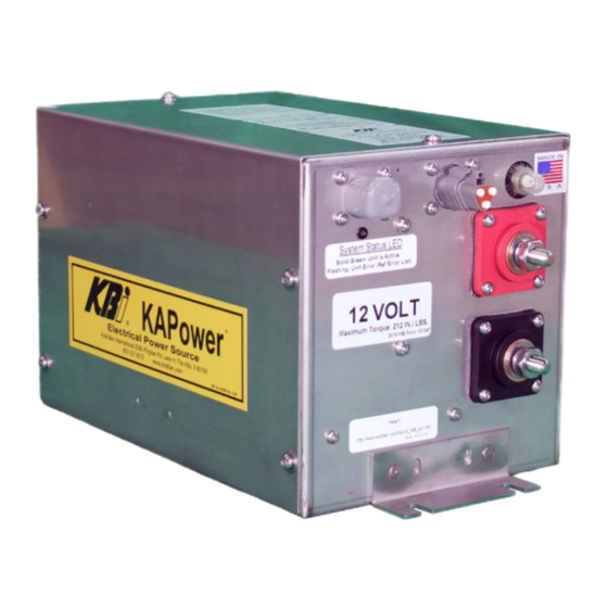
KAPower Starting Module
MKSM Models
INSTALLATION – OPERATION MANUAL
Gen 3 (12 Volts or 24 Volts)
KBI/Kold-Ban International, Ltd.
8390 Pingree Road, Lake In The Hills, Illinois 60156-9637 U.S.A.
(800) 527-8278, (847) 658-8561, Fax (847) 658-9280, www.koldban.com
ATA VMRS - T44 KLDBN
KBI® KAPower® © 2020 KBI Form #131498
Advertisement
Table of Contents

Summary of Contents for KBi KAPower MKSM Series
- Page 1 Gen 3 (12 Volts or 24 Volts) KBI/Kold-Ban International, Ltd. 8390 Pingree Road, Lake In The Hills, Illinois 60156-9637 U.S.A. (800) 527-8278, (847) 658-8561, Fax (847) 658-9280, www.koldban.com ATA VMRS - T44 KLDBN KBI® KAPower® © 2020 KBI Form #131498...
- Page 2 CAUTION indicates a hazardous situation which, if not avoided could result in equipment damage and/or equipment failure. KBI/Kold-Ban International, Ltd. accepts no responsibility or liability for any of its products that are improperly used. The safety information in this manual is provided as a guide for the user, and is not a substitute for proper training and usage.
-
Page 3: Table Of Contents
PARTS LIST ..................................4 TABLE OF CONTENTS ITEMS NEEDED FOR INSTALLATION........................4 INTRODUCTION ................................. 5 KAPower Advantages ............................... 6 KAPower Basic Description ............................ 6 The KAPower Module ............................... 6 Electrochemical Double-Layer Capacitor (EDLC) ..................6 INSTALLATION .................................. 6 Electrical Cable Selection ............................8 Mounting the MKSM Unit ............................ -
Page 4: Parts List
MKSM Enclosure DPST Rocker Switch (IP 67 Rated) Figure 1: Parts List Items NOTE: Not all scenarios and installation methods are covered in this document. If your application does not match any identified in this document, please contact KBI for assistance. -
Page 5: Introduction
INTRODUCTION The MKSM enclosure houses a KAPower module, contactor, PLC Module (Programable Logic Controller), circuit breaker, cables, conductors, and connectors. KAPower is designed as an auxiliary power source to be installed in parallel with cranking batteries. It derives its power from batteries or an engine charging system and discharges this power when needed. -
Page 6: Kapower Advantages
KAPower Advantages • Stores Cranking Voltage Until Needed • Long Service Life – Upwards of a Million Cycles • Performance Virtually Unaffected by Temperatures • Increases the Life of Batteries • Requires NO Maintenance • Safe and Easy to Install KAPower Basic Description The KAPower module is an energy storage device. - Page 7 Table 1: Specifications Specifications 6 Cell Unit 10 Cell Unit 10 Cell Unit 12 Cell Unit Electrical Characteristics Operating Voltage Window 6 – 14.5V 6 – 14.5V 12 – 29V 12 – 29V Maximum Voltage Minimum Voltage Internal Resistance 0.0011 ohms 0.0008 ohms 0.0019 ohms 0.0022 ohms...
-
Page 8: Electrical Cable Selection
CAUTION Electrical resistance in a circuit is the consumer of the electrical energy. When installing a KAPower Module, keep resistance to a minimum. Short, heavy cables, and clean cable connections are essential to reducing the amount of resistance in a circuit. CAUTION When selecting a location for installation, make sure that the KAPower MKSM module will clear any lids and other movable parts. -
Page 9: Mounting The Mksm Unit
The 4 Pin Deutsch connector has been supplied with a mating connector. Be sure to follow proper wire schemes as identified in the diagrams. The supplied DPST switch may be installed in addition to or paralleling the existing key- start switch. Locate and install the DPST switch in a convenient location relative to the key switch. - Page 10 Figure 2: Typical Cable Installations...
- Page 11 Material: Shell: 16ga SS 304 2B Cover: 18ga SS 304 2B Weight: 21.5lb (9.75Kg) Figure 3: Six (6) Cell MKSM...
- Page 12 Material: Shell: 16ga SS 304 2B Cover: 18ga SS 304 2B Weight: 32.5lb (14.75kg) Figure 4: Ten (10) and Twelve (12) Cell MKSM...
-
Page 13: General Wiring Installation Procedure
Also used for boats with multiple engines not using the DPST installation method. NOTE: Not all scenarios and installation methods are covered in this document. If your application does not match any identified in this document, please contact KBI for assistance. Theory of Operation, Explaining how the MKSM Module Works: Once installed and wired properly, the LED on the end-faceplate of the MKSM will be illuminated green whenever the MKSM contactor relay is closed. - Page 14 KAPower module. The LED may even begin to “cycle” depending on the vehicle/vessel, or system voltage during the recharging events. The J1939 connector is used for KBI factory programing only. Contact KBI for details.
- Page 15 Engine Start Signal Input CONNECTORS LOCATED ON THE END-FACEPLATE OF THE MKSM ENCLOSURE Figure 5: General Wiring Installation...
- Page 16 Wire the DPST switch by replacing the existing vehicle, vessel, or equipment push button engine starting switch with the KBI supplied DPST switch. Then find and wire the appropriate PLC input (pin 4) as based and depicted on Figure 5, and Figure 6. Do not connect any wiring to the J1939 Connector.
- Page 17 Figure 6: Standard MKSM Schematic (MKSMXXX00 Models)
-
Page 18: Installation Variation #1: For Boats Using A Push Button Or Key-Switch For Single Engine Starting
When installing MKSM on a boat that incorporates key switch starting, no rocker switch or push button replacement switch is required. NOTE: If the OEM engine manufacturer or the boat builder reviews the KBI MKSM Theory of Operation (page 13 + 14) and the requirements for DPST-type functionality, then incorporating the DPST-type function and engineering it into the factory build key- switch should be no problem. - Page 19 The PLC inside the MKSM needs power at pin four from a source, such as the key-switch, that provides power only when the boat is in operation. See Figure A1. Example of existing key-switch. “S” Terminal Power To Pin 3 of MKSM Note: See figure A2 for alternate source.
- Page 20 NOTE: “S” terminal receives power when the key-switch initiates an engine starting event. The power is also supplied to Pin 3 of the MKSM, bringing the MKSM online to supply engine starting power. Engine 1 “S” terminal power to pin 3 of KSM can be taken directly from starter.
-
Page 21: Installation Variation #2: For Boats Using A Push Button Or Rocker Switch For Engine Starting With Multiple Engines
The original OEM circuit does that, just as it normally would. All the MKSM is doing is making sure there is power available. After the engines start, the KBI MKSM PLC senses the engine has started (via voltage from Pin 4) and takes over control of the MKSM circuit and recharges the unit. - Page 22 Note: All Grounds Commons NOTE: An automatic charge relay (ACR) and house battery are shown for reference only. Not all installations require or use house batteries, but in such a scheme, the house battery could also be used for “emergency” power. Figure B1: Multiple Engine Option For use with MKSMXXX02 Models...
- Page 23 Ignition Circuit Power to the MKSM pin 4, For whenever the key is on and the boat is in operation. Start Connection 1 Existing push button, Or rocker switch connection Start Connection 2 Existing push button, Or rocker switch connection Note: Multiple DPSTs can be used, wired parallel to the MKSM, one for each engine.
- Page 24 Note: Multiple DPSTs can be used, wired parallel to the MKSM, one for each engine. Figure B3: Standard DPST Install (For use with MKSMXXX02 Models)
-
Page 25: Also Used For Boats With Multiple Engines Not Using The Dpst Installation Method
When installing MKSM on a boat that incorporates keypad buttons, there are no mechanical switches or buttons to push for engine starting. Using the KBI DPST method of installation, MKSM activation is not an option. Instead you will be using power to activate the MKSM from the engine’s starter motor “S”... - Page 26 Connector Input, Signal from Each Engine Starters “S” Terminal: Pin A: Engine 1 Start Signal Pin B: Engine 2 Start Signal Pin C: Engine 3 Start Signal Pin D: Engine 4 Start Signal Pin E: Engine 5 Start Signal Figure C1: Alternate Method For use with MKSMXXX01 Models...
- Page 27 The PLC inside the MKSM needs power (approximately 2.5 amps) from a source, such as a key switch, that provides power only when the boat is in operation. Consider this additional 2.5 amps of power and how it may influence the source. This new circuit should be protected with a 5-amp fuse or circuit breaker per ABYC standards.
- Page 28 Figure C3: Multiple Engine MKSM Schematic (For use with MKSMXXX01 Models)
-
Page 29: Operation
It is important to MONITOR the voltage when charging the KAPower module to its Maximum Voltage. This is the main purpose and function of the PLC. If the voltage exceeds these ranges, contact KBI for further troubleshooting instructions. Failure to adhere to these specifications will result in premature module failure. -
Page 30: Troubleshooting And Maintenance
TROUBLESHOOTING AND MAINTENANCE Maintenance of the KAPower module within the MKSM enclosure is not required provided that the operating conditions are proper, and that the requirements specified in this manual are observed. NOTE: During scheduled maintenance you can disconnect the 4-pin deutsch connector from the MKSM faceplate then start the engine using only the vehicle’s or vessel’s own key switch or start button. -
Page 31: To Check Mksm Internal Circuit
Jump pins 1 and 2 on the four-pin connector, the contactor should activate and make a “clunk” sound. If not, contact KBI for assistance. If experiencing problems check the integrity of the vehicle or vessel side of the wiring harness for issues such as shorts, corrosion, chafing, or bad connections and components. -
Page 32: Storage
Climate control systems are not required. The required storage temperature range is -76º to 158ºF (-60º to 70ºC). TRANSPORTATION The KAPower MKSM modules can be shipped in approved corrugated cardboard, wooden, or plastic containers. For more information on transportation, contact KBI. -
Page 33: Optional Voltmeter Harness
Connect the eyelet over the existing ground connection on the negative post of the MKSM. A voltmeter can then be installed at the butt splices coming from the Weather Pack connector. Note: Not all KSM models can use external voltmeter, contact KBI for details. -
Page 34: Limited Warranty
10.0 LIMITED WARRANTY The KAPower module itself, inside the MKSM, is guaranteed against defects in material and workmanship for three (3) years from date of purchase. All other MKSM components are guaranteed against defects in material and workmanship for one (1) year from the date of purchase.
Need help?
Do you have a question about the KAPower MKSM Series and is the answer not in the manual?
Questions and answers