Table of Contents
Advertisement
Available languages
Available languages
AWSMAN–E1JT–1307 IT EN
Leggere sempre le istruzioni prima dell'installazione
Always read the instructions before the installation
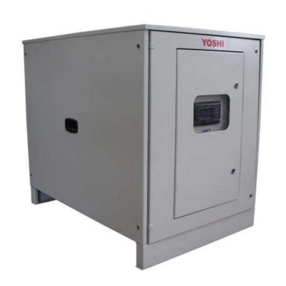
AWS E1J - TWIN
YOSHI
®
Yoshi Air Water System
MANUALE DI INSTALLAZIONE – INSTALLATION MANUAL
40 HP - 50 HP
Al termine dell'installazione, far sempre eseguire il primo avviamento dal
Centro di Assistenza Tecnica Autorizzato AISIN di zona.
After the installation, always call the local AISIN Authorised Service Centre to perform the outdoor
and indoor units commissioning.
Advertisement
Table of Contents

Summary of Contents for Aisin YOSHI AWS E1J TWIN
- Page 1 40 HP - 50 HP Al termine dell’installazione, far sempre eseguire il primo avviamento dal Centro di Assistenza Tecnica Autorizzato AISIN di zona. After the installation, always call the local AISIN Authorised Service Centre to perform the outdoor and indoor units commissioning.
- Page 3 DICHIARAZIONE CE DI CONFORMITA’ CE DECLARATION OF CONFORMITY Dati identificativi del fabbricante: Identification of the manufacturer: Tecnocasa s.r.l. Sede legale: Via Manzoni, 17 60025 Loreto (AN) Italia Dichiara che l’insieme per la macchina YOSHI AWS (Air Water System) Declare that the assembly for the YOSHI AWS (Air Water System) unit: Modelli: AWS40HP E1J Matricola: vedi targa dati...
- Page 4 Il non rispetto delle procedure riportate nel manuale può causare malfunzionamenti o danni all’unità. È necessario leggere e capire totalmente il contenuto di questo manuale prima di iniziare l'installazione dell'unità AWS YOSHI. Al termine dell’installazione, far sempre eseguire il primo avviamento dal Centro di Assistenza Tecnica Autorizzato AISIN di zona.
-
Page 5: Table Of Contents
INDICE Caratteristiche tecniche Dati tecnici e caratteristiche unità AWS ................6 Norme generali per l’installazione ..................6 Prima dell’installazione ......................7 Accessori in dotazione......................7 Materiali da procurarsi ......................7 Utilizzo di miscela acqua glicole ..................8 Installazione unità AWS Installazione ........................... -
Page 6: Dati Tecnici E Caratteristiche Unità Aws
1 Dati tecnici e caratteristiche unità AWS AWS 40 HP – E1J AWS 50 HP – E1J Unità TWIN 16+16 HP 16+20 HP 20+20 HP 16+25 HP 20+25 HP 25+25 HP Codice potenza totale unità esterne GHP collegate P900 P1010 P1120 P1160 P1270... -
Page 7: Prima Dell'installazione
2 Prima dell’installazione Accessori in dotazione I seguenti accessori sono forniti in dotazione con l’unità AWS YOSHI. Nome Manuale Schema quadro Filtro ad Y da 2 1/2” per Contro flange DN 65 installazione elettrico tubo acqua [guarnizioni] [guarnizioni] ove previste 1 - [2] 2 - [2] Quantità... -
Page 8: Utilizzo Di Miscela Acqua Glicole
3 Utilizzo di miscela acqua glicole Utilizzare miscele di acqua e liquidi antigelo per abbassare il punto di congelamento dell’acqua. Il liquido maggiormente usato come anticongelante è il glicole etilico. La tabella riporta i fattori di riduzione della potenza frigorifera e della portata della pompa del modulo idronico in funzione della temperatura dell’acqua e della percentuale in peso di glicole nella miscela. -
Page 9: Dimensioni Esterne, Attacchi Idraulici E Frigoriferi
4.2 Dimensioni esterne, attacchi idraulici e frigoriferi La tabella seguente riporta i diametri degli attacchi idraulici, frigoriferi, i diametri delle tubazioni e la loro posizione nei vari modelli di modulo idronico. CONNESSIONI FRIGORIFERE ED IDRAULICHE UNITÀ TWIN Attacchi idraulici Inch L’unità... -
Page 10: Spazi Per L'installazione
4.3 Spazi per l’installazione Gli spazi minimi necessari per controlli e manutenzione sono indicati nelle tabelle sottostanti AVVERTENZA Gli spazi minimi di installazione indicati sono necessari a garantire la corretta circolazione d’aria, il controllo e la manutenzione dell’unità AWS. Il non rispetto di tale prescrizione può causare lesioni personali al manutentore o malfunzionamenti dell’unità. -
Page 11: Linee Frigorifere
Tutte le saldature delle linee frigorifere AWS – GHP devono essere realizzate in conformità con quanto prescritto nel manuale di installazione dell’unità esterna GHP AISIN (saldatura in atmosfera controllata con azoto). Il non rispetto di tale prescrizione comporta la cessazione immediata della... -
Page 12: Specifiche Delle Tubazioni
ATTENZIONE Gli attacchi delle tubazioni frigorifere dell’unità AWS YOSHI hanno diametri differenti da quelli prescritti per le tubazioni di collegamento con l’unità esterna GHP AISIN. È pertanto necessario utilizzare opportuni adattatori (non in dotazione). Per il corretto dimensionamento delle linee frigorifere fare riferimento alla tabella sottostante. -
Page 13: Carica Aggiuntiva Gas Refrigerante
AVVERTENZA La carica aggiuntiva di gas refrigerante deve essere realizzata in conformità con quanto prescritto nel manuale di installazione dell’unità esterna GHP AISIN. Il non rispetto di tale prescrizione comporta la cessazione immediata della garanzia e può causare malfunzionamenti dell’unità. -
Page 14: Circuito Frigorifero E Circuito Idraulico
6 Circuito frigorifero e circuito idraulico 6.1 Modalità raffreddamento Il refrigerante (R410A) elaborato dalle GHP arriva nella parte bassa degli scambiatori di calore del modulo AWS, passando attraverso le valvole elettroniche di espansione che ne riducono la pressione. Esso evapora negli scambiatori a piastre sottraendo calore all’acqua, che fluisce contro corrente rispetto al gas stesso, tornando poi alla GHP in uno stato di vapore surriscaldato. -
Page 15: Collegamenti Elettrici
• MAI alimentare elettricamente l’unità prima del collaudo finale che deve essere sempre eseguito dal Centro di Assistenza Tecnica Autorizzato AISIN. Il non rispetto di tale prescrizione può causare danni irreversibili all’unità e comporta la cessazione immediata della validità della garanzia. -
Page 16: Schema Dettagliato Dei Collegamenti Elettrici
7.2 Schema dettagliato dei collegamenti elettrici... -
Page 17: Accessori Modulo Idronico
8 Accessori modulo idronico 8.1 “Controller Plus”: Pannello di Controllo e Sonda Serbatoio di Accumulo 8.1.1 Pannello di controllo Pannello di controllo per la gestione a distanza del modulo idronico con il quale è possibile il controllo e la gestione di un solo modulo da postazione remota. Il cavo schermato di collegamento del pannello al modulo può... -
Page 18: Pannello Di Controllo
Il quadro elettrico dell’AWS YOSHI è rappresentato in figura. Nel caso di anomalia dell’unità esterna GHP AISIN, il codice di allarme relativo all’anomalia viene visualizzato sul display del controllo remoto. Verificare la tipologia di allarme sul manuale di... -
Page 19: Regolazione Del Modulo Idronico
In caso contrario la pompa di circolazione del primario continua a funzionare, ma il sistema smette comunque di erogare capacità, fermando la GHP AISIN. Esempio di modulazione in riscaldamento: La temperatura di set point in riscaldamento, ovvero il parametro “Tset caldo”, può variare in un intervallo compreso tra 30°C e 48°C. -
Page 20: Impostazione Dell'offset
L’unità AWS YOSHI permette inoltre di regolare l’offset per la temperatura di set point, ovvero la temperatura di ritorno dell’acqua sul circuito primario alla quale far ripartire la GHP AISIN ed iniziare nuovamente ad erogare potenza. I parametri “Offset Tset” sono modificabili dal menu utente dell’unità... -
Page 21: Schemi Di Impianto
11.1 Impianto con accumulo centrale Questa soluzione è consigliata dal costruttore per ottimizzare il funzionamento dell’unità GHP AISIN nel caso di impianti a fan coil. In questa configurazione, la portata del circuito secondario deve essere sempre minore od uguale a quella del circuito primario. -
Page 22: Centrale Termo/Frigorifera Aws E1J Twin
11.4 Centrale termo / frigorifera AWS E1J TWIN... -
Page 23: Centrale Termo/Frigorifera Aws E1J Twin Contabilizzazione Consumi
11.5 Centrale termo / frigorifera AWS E1J TWIN contabilizzazione consumi... -
Page 24: Centrale Termo/Frigorifera Aws E1J Twin A Portata Variabile Senza Disgiuntore Idraulico (U.t.a.)
11.6 Centrale termo / frigorifera AWS E1J TWIN a portata variabile senza disgiuntore idraulico (U.T.A.) -
Page 25: Centrale Termo / Frigorifera Aws E1J Twin A Portata Variabile Con Disgiuntore Idraulico (Fan Coil)
11.7 Centrale termo / frigorifera AWS E1J TWIN a portata variabile con disgiuntore idraulico (fan coil) -
Page 26: Diagnosi Delle Anomalie (Riferimento)
10.000 ore Allarme avviso Contattare il centro di assistenza • di funzionamento. A13S1 manutenzione tecnica Aisin. Necessità di manutenzione ordinaria. La pompa di calore ha Resettare le ore di funzionamento • Allarme manutenzione raggiunto le 10.000 ore di... - Page 27 Verificare il codice visualizzato sulla • GHP. Premere UP per gli allarmi in Allarme GHP2 A15S1 corso e DOWN per quelli in STAND- Allarme Sonda Verificare la sonda e il cablaggio A16S1 • Temperatura Ritorno 2 Allarme Sonda Verificare la sonda e il cablaggio A17S1 •...
- Page 28 Tutte le anomalie visualizzabili sul display del controllo remoto sono sotto elencate. In caso di anomalia, contattare il Centro di Assistenza Tecnica Autorizzato Aisin che esegue la manutenzione dell’unità esterna. Indicazioni lampeggianti (ON per indicazione fissa) Display Tipo di (OFF indicazione spenta) Unità...
- Page 29 Indicazioni lampeggianti Possibili cause (ON per indicazione fissa) Display Tipo di Unità anomalia (OFF indicazione spenta) Codice Spia Scritta Codice errore esterna errore ON/OFF TEST Unità • 91-0 Allarme surriscaldamento scarico compressore (>120°C) Errore funzionamento • 87-0,2 Allarme surriscaldamento ripresa compressore (> 40°C) •...
- Page 30 Before beginning the installation of the YOSHI AWS unit, read and fully under stand the contents of this manual. After the installation, always call the local AISIN Authorised Service Centre to perform the outdoor and indoor units commissioning.
- Page 31 INDEX Specifications AWS unit specifications...................... 32 Installation prescriptions ....................32 Before installation ....................... 33 Parts provided ........................33 Locally procured parts ...................... 33 Use of water and glycol mixture..................34 AWS unit installation Installation..........................34 Selecting the location for installation ................34 External dimensions, hydraulic and refrigerant gas connections........
- Page 32 1 AWS unit specifications AWS 40 HP – E1J AWS 50 HP – E1J TWIN unit 16+16 HP 16+20 HP 20+20 HP 16+25 HP 20+25 HP 25+25 HP Capacity code of the connected GHP outdoor unit P900 P1010 P1120 P1160 P1270 P1420 82,0...
- Page 33 2 Before installation Parts provided The following parts are provided with the YOSHI AWS unit. Name Installation Control box 2” Y-shape filter for water DN 65 flanges EN 1092 manual wiring diagram pipe [gaskets] [gaskests] where provided 1 - [2] 2 –...
- Page 34 3 Use of water and glycol mixture Use mixtures of water and antifreeze fluid to lower the freezing point of water. The liquid most commonly used as antifreeze is ethylene glycol. The table shows the reduction factors of the cooling capacity and the capacity of the pump of the AWS as a function of the water temperature and percentage by weight of glycol in the mixture.
- Page 35 4.2 External dimensions, hydraulic and refrigerant gas connections The table below shows the diameters of the water connections, refrigerant, piping diameters and their position in the various models of AWS. TWIN UNIT REFRIGERANT WATER AND REFRIGERANT GAS CONNECTIONS Water connections Inch The uniti s supplied with DN 65 (EN 1092 1/13) flanges 2,5 or higher...
- Page 36 4.3 Installation space Clearances for maintenance and inspection operations are described in the tables below. CAUTION • The minimum installation spaces are necessary to provide room for air circulation, inspection and maintenance of the AWS unit. Failure to observe this prescription could result in injury to the maintenance personnel and damage to the unit.
- Page 37 WARNING All the welding operations on the AWS – GHP refrigerant gas piping must be always performed in accordance with instructions and prescriptions mentioned in the AISIN GHP installation manual (brazing with nitrogen flow). Failure to observe this prescription makes the warranty no longer valid and could result in malfunction...
- Page 38 It is forbidden to connect direct expansion indoor units and YOSHI AWS to a single AISIN GHP outdoor unit simultaneously. The YOSHI AWS can be only connected to a specific AISIN GHP outdoor unit for AWS with the same capacity.
- Page 39 The refrigerant extra charge must be done in accordance with the procedures described in the AISIN GHP installation manual. Failure to observe this prescription makes the warranty no longer no longer valid and could result in malfunctioning of the YOSHI AWS unit.
- Page 40 6 Refrigerant circuit and hydraulic circuit 6.1 Cooling mode The refrigerant (R410A) processed by the GHP flows through electronic expansion valve and enters the lower part of the AWS unit heat exchanger at low pressure. The gas evaporates in the plate heat exchanger by taking heat from the counter current water flow.
- Page 41 NEVER switch on the power supply before the final commissioning is performed by the AISIN Authorised Service Centre. Failure to observe this prescription makes the warranty no longer valid and could result in malfunction and/or damage to the YOSHI AWS unit.
- Page 42 7.2 Detailed wiring diagram...
- Page 43 8 AWS Accessories 8.1 Controller Plus: Control Panel and Probe Temperature Buffer Tank 8.1.1 Control panel Control panel for the remote management of the AWS with which is possible to control and management of a single module from a remote location. The shielded cable connecting the panel to the module has a maximum length of 60 meters.
- Page 44 The YOSHI AWS control panel is represented below. In case of AISIN GHP outdoor unit malfunction, the error code will be displayed on the remote controller fitted in the YOSHI AWS control panel. Check the failure type on the AISIN GHP installation manual.
- Page 45 10 AWS Set Point Adjustment 10.1 Control panel The unit AWS YOSHI has the possibility to vary the capacity delivered, in a range between 13% and 100% of rated power, as a function of the return water temperature on the primary circuit. The modulation of the capacity is adjusted according to a proportional band.
- Page 46 Example modulation in cooling: The set point temperature in cooling, ie the parameter "Tset cool", may vary in a range between 6°C and 15°C. The factory settings are: Tset cool= 8°C; Modulation Range = 5°C AWS Capacity Tset cool [°C] Modulation Max.
- Page 47 11.1 Central storage tank installation This layout is recommended by the manufacturer for fan-coil installations. to optimise the operation of the AISIN GHP. When choosing this layout always make sure that the water flow of the primary and the secondary circuits are balanced.
- Page 48 11.4 HVAC installation AWS E1J TWIN...
- Page 49 11.5 HVAC installation E1J TWIN proportional distribution of consumption...
- Page 50 11.6 HVAC installation AWS E1J TWIN variable flow rate no hydraulic separator (AHU)
- Page 51 11.7 HVAC installation AWS E1J TWIN variable flow rate with hydraulic separator (fan coil)
- Page 52 • Expansion valve driver and check which component is in A8S1 alarm 1 alarm The heat pump is about to Maintenance period reach the 10.000 hours of Contact the service centre Aisin A13S1 • warning operation. Need for routine maintenance.
- Page 53 The heat pump has Reset the hours of operation (See • Maintenance period reached 10.000 hours of page 82, service manual paragraph A14S1 alarm operation. Need for 13.3 "Reset hours of operation"). routine maintenance. Check the code displayed on • the GHP.
- Page 54 The table below shows all the error codes displayed on the remote controller fitted in the AWS control panel. In case of malfunction contact the AISIN Authorised Service Centre that usually maintains the GHP outdoor unit. Blinking indication (ON doesn’t blink)
- Page 55 Blinking indication (ON doesn’t blink) outdoor Type of failure (OFF led off) Possible cause Error code unit Error TEST Unit display code ON/OFF Disp. • 91-0 Compressor discharge temperature too high (>120°C) Operation failure • 87-0,2 Compressor intake temperature too high (> 40°C) •...
- Page 56 NOTE ………………………………………………………………………………………….. ………………………………………………………………………………………….. ………………………………………………………………………………………….. ………………………………………………………………………………………….. ………………………………………………………………………………………….. ………………………………………………………………………………………….. ………………………………………………………………………………………….. ………………………………………………………………………………………….. ………………………………………………………………………………………….. ………………………………………………………………………………………….. ………………………………………………………………………………………….. ………………………………………………………………………………………….. ………………………………………………………………………………………….. ………………………………………………………………………………………….. ………………………………………………………………………………………….. ………………………………………………………………………………………….. ………………………………………………………………………………………….. ………………………………………………………………………………………….. ………………………………………………………………………………………….. ………………………………………………………………………………………….. …………………………………………………………………………………………..
- Page 57 ………………………………………………………………………………………….. ………………………………………………………………………………………….. ………………………………………………………………………………………….. ………………………………………………………………………………………….. ………………………………………………………………………………………….. ………………………………………………………………………………………….. ………………………………………………………………………………………….. ………………………………………………………………………………………….. ………………………………………………………………………………………….. ………………………………………………………………………………………….. ………………………………………………………………………………………….. ………………………………………………………………………………………….. ………………………………………………………………………………………….. ………………………………………………………………………………………….. ………………………………………………………………………………………….. ………………………………………………………………………………………….. ………………………………………………………………………………………….. ………………………………………………………………………………………….. ………………………………………………………………………………………….. ………………………………………………………………………………………….. ………………………………………………………………………………………..
- Page 60 22/08/2013...
Need help?
Do you have a question about the YOSHI AWS E1J TWIN and is the answer not in the manual?
Questions and answers