Advertisement
Quick Links
Product Manual
WWW.HOBBYSTARLABS.COM
Copyright © 2016 HobbyStar
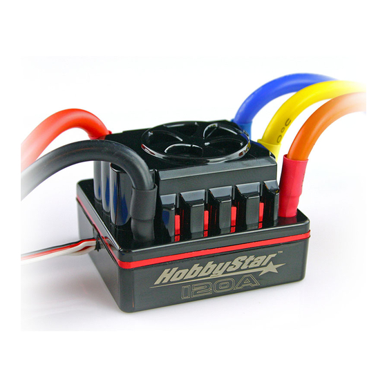
Sensored/Sensorless Brushless Speed Controller
for Car or Truck
Thank you for your purchasing this Brushless Electronic Speed Controller (ESC). This electronic
speed controller is specifically designed for operating Sensored/Sensorless brushless motors. High
power systems for RC models can be very dangerous and we strongly suggest that you read this
manual carefully. We have no control over the correct use, installation, application or maintenance
of these products, thus no liability shall be assumed nor accepted for any damages, losses or costs
resulting from the use of this item. Any claims arising from the operating, failure or malfunction, etc.
will be denied. We assume no liability for personal injury, property damage or consequential
damages resulting from our product or our workmanship. As far as is legally permitted, the
obligation for compensation is limited to the invoice amount or product in question.
Features:
Enhanced throttle response, excellent acceleration, strong brakes and throttle linearity
Advanced software interface for setting up and firmware updates.
Uses LCD or LED program card for adjustments.
Multiple protection features: Low voltage cut-off protection, over-heat protection and
throttle signal loss protection
Compatible with brushless sensored/sensorless motors.
Setup
Please check all connections carefully and make sure they are connected properly.
Sensored Mode:
When using a Sensored Brushless motor, the Blue motor wire A, the Yellow motor wire B and the
Orange motor wire C of the ESC must be connected with the Sensored motor wire A,B,C
respectively. It is necessary to connect the Sensor wire to the "Sensor" socket on the ESC. It is
important to not alter the order of motor wires when using with a sensored motor.
Sensorless Mode:
When using a Sensorless Brushless motor, the Blue motor wire A, the Yellow motor wire B and the
Orange motor wire C of the ESC can be connected with the motor wires in any order. If the motor
runs in the opposite direction, please swap any two wire connections.
Connection to the Receiver
Black wire
RX-
Red wire
RX+6.0V
White wire
RX-Signal
LEDs:
Sensored/sensorless function
When the Power wires on the ESC are connected with the battery pack, the ESC can automatically
identify the motor type (Sensored/Sensorless) via indicated LEDs. Sensored cable must be
removed for ESC to operate in sensorless mode.
Function
LED
Low voltage of the battery
Red LED
Over-heat of the ESC and motor(95'C)
Blue LED
Sensored motor
Blue and Red LED
Sensorless motor
Blue LED
Throttle Range Calibration
The ESC must be calibrated when used for the first time, and any time a new radio/receiver is
used.
For the first time using transmitter or changing the transmitter you must set up Throttle Range
Calibration.
1. Switch off the ESC, then connect ESC to battery and turn on the transmitter; set the EPA/ATV
(travel) value of the throttle channel to the maximum setting in both directions (can be 100%,
125%, 150% etc. depending on radio).
NOTE: Some radios must have throttle channel set to REV (e.g. Futaba, Flysky).
NOTE: If your radio is equipped with ABS braking it must be disabled for calibration.
2. Hold the "set" button down and turn on ESC while still holding the "set" button. After about 4
seconds the LED will turn SOLID BLUE. Release the "set" button, and immediately apply full
throttle and hold it. The LED will FLASH RED and then turn SOLID RED. Motor will beep.
3. Immediately apply full brake (do not stop at neutral). The LED will FLASH BLUE and then turn
SOLID BLUE. Motor will beep.
4. Return throttle to neutral position. RED and BLUE LEDs will flash, and then turn solid and then
off. Motor will beep. Throttle has been calibrated.
5. Turn the ESC back ON. The ESC is now ready to use.
Programmable Items and default settings:
Default settings are shown in the grey boxes.
Programmable Value
Programmable
Items
1
2
3
4
5
Cut-off Voltage
2.6V/cell
2.8V/cell
3.0V/cell
3.2v/cell
3.4V/cell
Forward
Forward
Forward
Running Mode
with pause
w/o
/Reverse
then
Reverse
Motor timing
Very Low
Low
Normal
High
Very High
Initial
Low
Medium
High
Very High
Acceleration
Throttle
percent
20%
30%
40%
50%
60%
Reverse
Throttle Limit
0%
20%
30%
40%
50%
Percentage
10%
20%
30%
40%
50%
Braking
Percentage Drag
0%
4%
8%
12%
15%
Brake
Motor Rotation
Normal
Reverse
Neutral Range
2%
3%
4%
5%
6%
Sensored/Sensorless brushless ESC general information
1. Cutoff Voltage
Automatically detects number of cells
ESC automatically detects number of cells in battery pack. You can program the cut-off voltage as
an individual cell voltage. For example, if you set cut-off to a 3.2v. cell, a 2S LiPo pack will cut-off at
a total pack voltage of 6.4v. Cut-off can be programmed via program card or PC software.
When using NiMH or NiCd batteries you do not need to set a cutoff voltage to protect the batteries.
If you are using more than 6-cell NiMH or NiCd batteries, you must adjust the cutoff voltage. For
example if you are using an 8-cell pack of NiMH batteries, you would use a cutoff of 5.6V volts (8 x
LED Status
Blinking
Blinking
ON
ON
6
7 8
9
NO-Cut Off
70%
00%
90%
100%
60%
70%
80%
90%
60%
70%
80%
100%
20%
25%
30%
10%
Advertisement

Summary of Contents for HobbyStar 80A
- Page 1 Black wire Automatically detects number of cells Red wire RX+6.0V Copyright © 2016 HobbyStar White wire RX-Signal ESC automatically detects number of cells in battery pack. You can program the cut-off voltage as an individual cell voltage. For example, if you set cut-off to a 3.2v. cell, a 2S LiPo pack will cut-off at LEDs: a total pack voltage of 6.4v.
- Page 2 5. When you are done making adjustments, click the "Apply” button, and settings will be saved to 0.7V = 5.6V). When the voltage of the batteries packs is within 8.4-12.6V, the ESC will also very tough on the batteries as the amperage draw can be very high. If your vehicle cuts out, the ESC.
Need help?
Do you have a question about the 80A and is the answer not in the manual?
Questions and answers
is there a replacement fan for hobbystar 120v esc v2