Table of Contents
Advertisement
Quick Links
Advertisement
Table of Contents

Summary of Contents for Elk Products Ness M1XEP
- Page 1 Ness-M1XEP Ethernet Interface INSTALLATION MANUAL...
-
Page 2: Table Of Contents
Table of Contents Features and Specifications ......................3 Basics of Networking ........................4 Installation and Hookup ........................ 5 Configuration and Setup ......................6 Basic Network Setup ........................Send Changes to M1XEP and Save ....................Setup of User Names & Passwords ....................Email Notification Setup ........................ -
Page 3: Features And Specifications
Features and Specifications APPLICATION: The Ness-M1XEP is an Ethernet Device Server with a RS-232 Serial Port Interface. It may be used to connect a Control in the M1 Family to an Ethernet network using TCP-IP protocol. It features a secure embedded web server with a user interface built on a Java applet, email event notification, and FIPS compliant encryption algorithms for security sensitive environments. -
Page 4: Basics Of Networking
Basics of Networking The installer must have a basic understanding of Ethernet setup to install and configure the M1XEP. If you do not have this basic knowledge, please seek the assistance of a network professional. Internet Cable Satellite Wide Area Network Location Connection to outside the local network may require assistance from others,... -
Page 5: Installation And Hookup
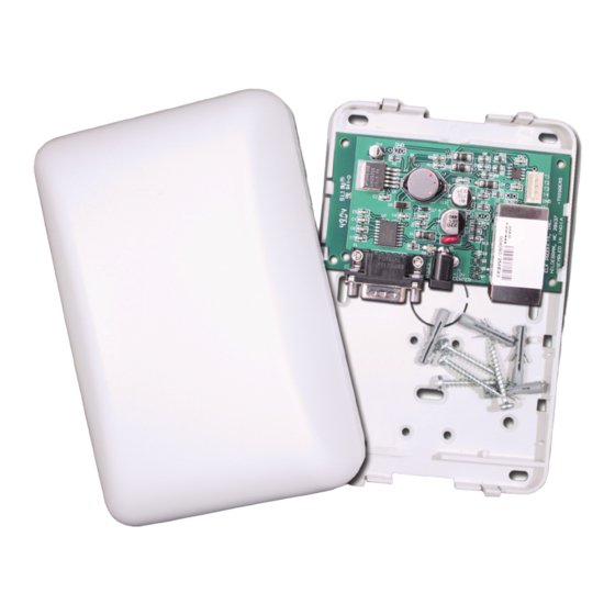
Installation and Hookup The following connections are required for the M1XEP Ethernet Interface. a. The DB9M 9-pin male connector should be connected to the DB9F 9-pin female serial port (port 0) on the Control using a standard 9-pin male to female serial cable (included). The M1Gold has the main serial port (port 0) on board, while the M1EZ8 requires the M1EZ8MSI Main Serial Interface to provide the port 0 connection. -
Page 6: Configuration And Setup
Configuration and Setup The M1XEP is supported by the M1 Family of controls with firmware version 4.3.0 or later. The M1XEP software configuration utility is built into NessRP software version 1.5.0 or later. If you have an older version of firmware or NessRP software, current updates can be downloaded from the M1 Dealer Website (www.ness.com.au/m1). - Page 7 1.3. Highlight the M1XEP to be configured and click the 'Use Selected' button. This automatically copies the IP address and Port settings to the NessRP "Account Details" location and returns back to the setup screen. Click 'Close' to exit this screen. 1.4.
-
Page 8: Send Changes To M1Xep And Save
2. Send Changes to the M1XEP and Save Send the changes by clicking the send button located at the bottom of the setup screen. You may receive a message that informs you that the changes will cause the M1XEP to reconfigure itself, and it must be rebooted after the send is complete. -
Page 9: Email Notification Setup
4. Email Notification Setup (optional) The "Email" tab is where information regarding email notification is stored. a. Enter the SMTP server’s URL or IP address. This can be up to 48 characters long. Set the port value to the correct setting for outgoing mail. The default port setting is 25. If your mail server uses a different port, your Internet service provider or network administrator can provide you with the correct port setting. -
Page 10: Central Station Setup
5. Central Station Setup (optional) The M1XEP supports Alarm over Internet Monitoring to Central Stations that have an Osborne-Hoffman OH2000E receiver using the Contact ID format. Central Station Internet Monitoring is only supported by M1XEPs with firmware version 1.2.0. Internet monitoring requires setup of the M1XEP and a corresponding telephone account in the Control. Telephone account # 1 corresponds with CS1 in the M1XEP setup. - Page 11 After setting up the telephone account, click on the "M1XEP Setup" button. Select the Central Station tab. The IP address, port number, and account number for the Central Station are entered here. This information is obtained from the Central Station. When using alarm over internet monitoring, only 1 account number is required regardless of the areas checkmarked on the corresponding telephone account setup page.
-
Page 12: Notes On Router Setup
6. Notes on Router Setup 6.1. Port Forwarding Particular ports must be opened through the router to allow access to the M1XEP through the Internet. You must access the router's setup in order to open (port forward) these ports. The method for this differs from product to product. -
Page 13: Connecting Nessrp To The Control Over A Network
Connecting NessRP to the Control over a Network 1. Start the NessRP program and create or open an account. 2. Look at the lower right side of the "Account Details" screen for the two data entry blocks labeled: "System URL/IP" and "Port". -
Page 14: Updating The M1Xep Firmware
Updating the M1XEP Firmware If you are notified of a new firmware release, you can obtain the file and update the M1XEP using the following steps. To access and download firmware updates for M1 controls and peripherals, you have must a valid log on for the M1 Dealer Site. -
Page 15: Using The Virtual Keypad Application
Using the Virtual Keypad Application In order to access the M1XEPs built-in web application "M1 Virtual Keypad" your computer must have the current Java application software (at the time this manual was released the current version was 1.5.0) . There is no charge for this software and it may be downloaded and installed from www.java.com. - Page 16 3. The next screen is the User Name/Password prompt. Enter the User Name and Password that was setup using the M1XEP Setup utility in NessRP. Click 'OK' to continue. If you did not set up any usernames or passwords, you will not see this prompt.
- Page 17 6. The Welcome screen should appear next. This screen requires that a valid user code be entered in order to access the Virtual Keypad application. Enter a valid User Code and click 'Connect' or press Enter. 7. The first screen to appear is the Security screen. Along the left side of the screen there are additional buttons which may be used to access the automation functions such as: Lighting, Tasks, Climate (Temperature Sensors &...
- Page 18 Bypass: The bypass key (and # key) can be used to bypass zones. Press 'Bypass', the number of the zone to bypass and click 'Bypass' again. Status: The 'Status' button brings up a display of all zones defined in the currently selected area, along with their status (“Normal”, “Bypassed”, “Violated”) and state (“Short”, “Open”, “EOL”).
- Page 19 9. Click the 'Climate' button to bring up the following screen. This begins with Thermostat 1, showing its current temperature, mode, fan setting, and the Heat and Cool setpoints. A drop down box permits additional thermostats to be selected. Use the mouse to change any of the settings. The Up arrows raise the setpoint values and the Down arrows lower the setpoint values.
- Page 20 11. Click the 'Tasks' button to display the following screen. This screen populates itself with the names of any tasks that have been programmed in the Control with a name and the “Show” option enabled. A task can be activated by clicking the green button beside of the task. If there are too many tasks to fit on one screen, the word 'Next>' will illuminate along the bottom of the screen.
-
Page 21: Glossary Of Terms
Glossary of Terms Router- A communications device between networks that determines the best path between them for optimal performance. Routers are used in complex networks such as enterprise-wide networks and the Internet. Port - The identifier used by Internet transport protocols to distinguish among multiple simultaneous connections to a single destination host. -
Page 22: Troubleshooting Guide
Troubleshooting Guide Problem Possible Solutions NessRP cannot "Find" the M1XEP Verify that the M1XEP is powered up and connected to the M1 Control Wait 1 to 2 minutes after powering up the M1XEP for the initialization process to complete before NessRP can "Find" the M1XEP Verify all cable connections and check to see if green LED on the RJ45 connector is blinking, indicating network traffic. - Page 23 Problem Possible Solutions Web Browser does not show the true status Check serial port 0 transmit options in Globals. These options can be of the M1 Control accessed through NessRP on the Special tab of the Globals screen, or through the keypad bay accessing Menu 9-Installation Programming, Sub-Menu 7-Global System Definitions.
- Page 24 www.ness.com.au/m1 email m1support@ness.com.au...
Need help?
Do you have a question about the Ness M1XEP and is the answer not in the manual?
Questions and answers