
Subscribe to Our Youtube Channel
Summary of Contents for Navico NSPL-500
- Page 1 NSPL-500 AIS/VHF antenna splitter User Manual NSPL-500 ENGLISH www.bandg.com | www.simrad-yachting.com | www.lowrance.com...
- Page 3 Documentation. This manual represents the product as at the time of printing. Navico Holding AS and its subsidiaries, branches and affiliates reserve the right to make changes to specifications without notice.
- Page 4 Disposal of this product and packaging About your AIS/VHF antenna splitter About AIS What’s in the box? Electrical connections Installation Preparing for installation VHF antenna VHF radio AIS transceiver FM radio Power cable Installation procedures Operation Indicator functions Troubleshooting Specifications Contents | NSPL-500 User Manual...
-
Page 5: Table Of Contents
Position of the VHF antenna connector Figure 7 Position of the VHF radio connector Figure 8 Position of the AIS transceiver connector Figure 9 Connecting the power supply and optional FM output Figure 10 Indicator location on the NSPL-500 unit Contents | NSPL-500 User Manual... - Page 6 The information provided in this section assumes the NSPL-500 is connected to an AIS Class B transceiver. The warnings regarding RF emissions provided in the manual for the VHF radio being used with the NSPL-500 should also be noted prior to installation of the NSPL-500. ¼ Note: The NSPL-500 generates and radiates radio frequency electro- magnetic energy.
- Page 7 1.5 m away from the NSPL-500 and is connected to the NSPL-500 before power is applied. The system has a Maximum Permissible Exposure (MPE) radius of 0.6 m. This has been determined assuming the maximum power of the AIS transceiver and using antennas with a maximum gain of 3 db.
- Page 8 VHF antenna for both devices by using an AIS/VHF antenna splitter. The NSPL-500 is designed to work primarily with AIS class B trans- ceivers, although it will operate equally well with AIS receivers. About your AIS/VHF antenna splitter |...
-
Page 9: Figure 1 Items Included With The Product
• VHF radio connection cable This cable is used to connect a VHF radio to the NSPL-500. The cable has PL259 connectors at either end and requires a SO239 connector on the VHF radio. If your VHF radio does not have a SO239 connec- tor please contact your dealer for details of suitable adaptors. -
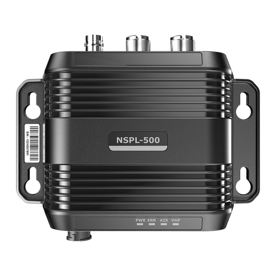
Page 10: Figure 2 Ais/Vhf Antenna Splitter Overview
Figure 2 shows an overview of the NSPL-500 unit. The NSPL-500 has a number of indicators which provide information to the user about the status of the NSPL-500. Please refer to section 4 for more details of the indicator functions. -
Page 11: Figure 3 Typical Installation Configuration
Power in NMEA 2000 Figure 3 Typical installation configuration In addition to the items provided with your NSPL-500 the following items will be required for installation: VHF antenna Connection to a suitable VHF antenna will be required for the NSPL- 500 to operate. - Page 12 Please note the following guidelines when selecting a location for your NSPL-500: • The NSPL-500 must be fitted in a location where it is at least 0.3 m from a compass or any magnetic device. • There should be adequate space around the NSPL-500 for routing of cables.
-
Page 13: Figure 4 Nspl-500 Dimensions
• The NSPL-500 is fully waterproof to ingress protection rating IP67, however it is recommended that the NSPL-500 is not subjected to extended periods of exposure to spray or submersion. • It is acceptable to mount the NSPL-500 either vertically or horizon- tally. -
Page 14: Figure 5 Nspl-500 Mounting
Figure 5 NSPL-500 mounting Step 2 - Connecting the VHF antenna Route the cable from the VHF antenna to the NSPL-500 and connect to the VHF antenna connector on the NSPL-500 as shown in Figure A standard marine band VHF antenna or AIS antenna should be used with the NSPL-500. -
Page 15: Figure 7 Position Of The Vhf Radio Connector
Step 3 - Connecting the VHF radio Using the VHF radio accessory cable provided with this product, route the cable from the VHF radio to the NSPL-500 and connect to the VHF radio connector on the NSPL-500 as shown in Figure 7. If the cable supplied is not long enough please contact your dealer for details of suitable extension cables. -
Page 16: Figure 8 Position Of The Ais Transceiver Connector
Step 4 - Connecting the AIS transceiver Using the AIS transceiver accessory cable provided with this prod- uct, route the cable from the AIS transceiver to the NSPL-500 and connect to the AIS transceiver connector on the NSPL-500 as shown in Figure 8. If the cable supplied is not long enough please contact your dealer for details of suitable extension cables. -
Page 17: Figure 9 Connecting The Power Supply And Optional
Fig. 9 Power and FM Step 5 - Connecting the power supply and optional FM output The NSPL-500 requires a 12 V or 24 V power supply typically pro- vided by the vessel’s battery. It is recommended that crimped and soldered lugs are used to connect the NSPL-500 to the power source. -
Page 18: Figure 10 Indicator Location On The Nspl-500 Unit
Operation Operation of the NSPL-500 is automatic and requires no user inter- vention. During operation the antenna splitter will share signals received at your VHF antenna with both the AIS transceiver and the VHF radio. When either the AIS transceiver or VHF radio transmits, the NSPL-500 will automatically sense the transmission and route the signal to the antenna. - Page 19 Function of the antenna splitter is the VHF radio is unaffected transmitting If the guidance given in the table above does not rectify the prob- lem you are experiencing please contact your dealer for further assistance. | 17 Troubleshooting | NSPL-500 User Manual...
- Page 20 Max input power, VHF port 25 W Min input power, VHF port 0.5 W AIS, VHF and Antenna port 50 Ohms impedance FM port impedance 75 Ohms Operating temperature -15ºC to +55ºC Ingress protection IP67 18 | Specifications | NSPL-500 User Manual...
- Page 21 NOTES: | 19 Specifications | NSPL-500 User Manual...
- Page 22 NOTES: 20 | Specifications | NSPL-500 User Manual...
- Page 24 201-0318 NSPL-500 Product Manual...
Need help?
Do you have a question about the NSPL-500 and is the answer not in the manual?
Questions and answers