Table of Contents
Advertisement
Quick Links
Advertisement
Table of Contents

Summary of Contents for Barudan BEXT 120V
- Page 1 B E X T Instruction Manual...
-
Page 2: Table Of Contents
Table of Contents Chapter 1 Safety Instructions ..........1‐ 1 1.Important Safety Instructions ........... 1‐ 2 2.Grounding Instructions .............. 1‐ 4 3.Warning Labels ................1‐ 5 Chapter 2 Introduction ............2‐ 1 ................1.Specifications 2‐ 2 ..................2.Features 2‐ 3 Chapter 3 Before Use ............ - Page 3 Chapter 4 Manual Operations .......... 4‐ 1 1.Color (Needle) Change ............... 4‐ 2 ..................2.Trimmer 4‐ 4 3.Thread Clamp ................4‐ 6 ..................4.Appliqué 4‐ 7 5.Change Frame ................4‐ 8 6.Bobbin Counter ................4‐ 9 7.Display Off ................. 4‐11 .................
- Page 4 Chapter 6 Memory Designs ..........6‐ 1 1.Selecting a Design ..............6‐ 2 2.Design Information ..............6‐ 3 3.Design Zoom ................6‐ 6 4.Deleting Designs from Memory ..........6‐ 8 5.Changing Design Names ............... 6‐ 9 6.Production Counts ..............6‐10 7.Thread Consumption ..............
- Page 5 Chapter 9 Embroidery ............9‐ 1 1.Start Point .................. 9‐ 2 2.Drive Mode ................. 9‐ 3 ..................3.Speed 9‐ 4 4.Speed Setting per Needle ............9‐ 5 ................... 5.Trace 9‐ 7 6.Frame Outline Display .............. 9‐10 7.Frame Outline Centering ............9‐11...
- Page 6 Chapter 10 Network ............10‐ 1 1.Before Using the Network System ......... 10‐ 2 2.Operator Code ................. 10‐ 4 3.Break Call ................10‐ 7 4.Operator Call ................10‐ 8 ................. 5.Time-Out 10‐11 6.Downloading Designs (Direct Downloading) ......10‐12 7.Downloading Designs (Schedule Downloading) .....
- Page 7 13.Production Totals per day ........... 11‐47 14.Schedule ................11‐48 15.Automatic 1 Color function insertion ........ 11‐56 Chapter 12 System ............12‐ 1 1.System File Structure ............. 12‐ 2 2.Updating System software ............12‐ 3 3.Updating Linux ................. 12‐ 5 4.Initializing Memory ..............
-
Page 8: Chapter 1 Safety Instructions
Chapter 1. Safety Instructions This chapter contains information on the following. 1. Important Safety Instructions 2. Grounding Instructions 3. Warning Labels 1‐1... -
Page 9: 1.Important Safety Instructions
1. Important Safety Instructions When using an embroidery machine, basic safety precautions should always be followed. This ■ machine is intended for commercial use. ■ The icons in the manual show the importance of the contents. Acknowledge the following descriptions beforehand. Read all instructions before using this machine Icons To reduce the risk of electric shock... - Page 10 ◆ Never operate this embroidery machine if it has a damaged cord or plug, if it is not working properly, if it has been damaged or is wet. Contact Barudan America technical support. ◆ Never operate the embroidery machine with any air openings blocked. Keep ventilation openings of the machine free from the accumulation of lint, dust, and loose cloth.
-
Page 11: 2.Grounding Instructions
2. Grounding instructions This product must be grounded. In the event of malfunction or breakdown, grounding provides a path of least resistance for electric current, to reduce the risk of electric shock. This product is equipped with a cord having an equipment-grounding conductor and a grounding plug. The plug must be plugged into an appropriate outlet that is properly installed and grounded in accordance with all local codes and ordinances. -
Page 12: 3.Warning Labels
3. Warning labels ■ Give attention during operation to the parts labeled. Warning Labels Contents Needle Hazard Warning Label Hair Warning Label Take-Up Lever Warning Label Frame Warning Label 1‐5... - Page 13 Warning Labels Contents Hook Warning Label Belt Warning Label 1‐6...
-
Page 14: Chapter 2 Introduction
Chapter 2 Introduction This chapter contains information on the following. 1. Specifications 2. Features 2‐1... - Page 15 1. Specification 1. Design Capacity 100 designs 2. Stitch Capacity 1 design-1million stitches / Total capacity: 10 million stitches 3. Display 5.7 inch Color LCD 640 x 480 dots (VGA) 4. Power Source AC100VSingle (+/-10%, 50/60Hz) AC200VSingle (+/-10%, 50/60Hz) 5. Power Consumption 1KVA /Varies for each model 6.
- Page 16 2. Features 1. Easy Operation The XT Automat is specially designed for Barudan embroidery machines. Linux is used for the OS, which allows high quality display and operation system. Graphic User Interface uses icons that are easily recognized for quicker learning of operations.
- Page 17 9. Design Information Design information such as total stitches, quantity produced, size, and thumbnail of the design can be seen on the screen. 10.Stitch Length Adjuster Swing parameter allows satin stitches to be automatically sewn slightly wider or narrower depending on the setting. This feature is helpful sewing small lettering when they need to be sewn with a bolder effect.
- Page 18 18.Stand-By (Resume) The machine can be turned OFF in the middle of a design. When powered back On, the machine resumes in the same position where the embroidery was stopped, even if the pantograph was moved when the machine was powered off. 19.Help function The machine can display help files saved on a USB Flash Drive.
-
Page 19: Chapter 3 Before Use
Chapter 3 Before Use This chapter contains information on the following. 1. Appearance and Components 2. Panel Switches 3. Powering the Machine On / Off 4. Origin Set 5. Stand-By and Drive Modes 6. Screen Structure 7. Information Screen 8. Design List Display Settings 9. -
Page 20: 1.Appearance And Components
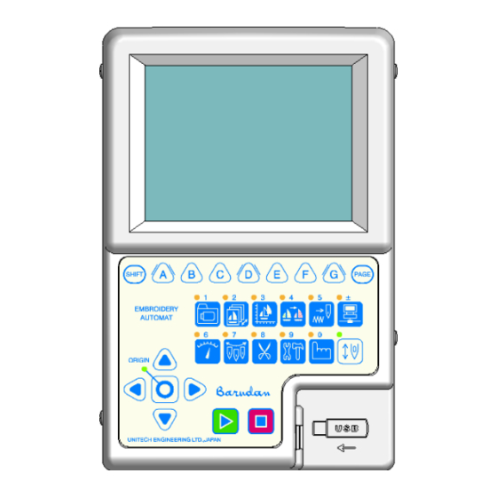
1. Appearance and Components ① ② ③ ⑤ ④ ⑥ ⑦ ⑧ ⑨ ⑩ ⑪ 3‐2... - Page 21 ⑪ ⑫ ⑬ 3‐3...
- Page 22 1. LCD Display Shows machine status, icons, and design information. 2. Icon key – A, B, C, D, E, F, and G-keys Operation buttons assigned to functions displayed on screen above by icons. 3. Page key Switches display screens. . Embroidery Display Screen” *Refer to “Section 7-4 in this chapter for details.
- Page 23 10. Stop Key The machine stops sewing. 11. USB(front:1 port back:1port) These are for USB connections. They are used for uploading and downloading design data and updating the system software. As an option, a bar code scanner can also be plugged in. 12.
- Page 24 2. Panel Switches Design Loading/Downloading Key Loads and downloads designs from the USB port etc. Numeric Key: 1 Design Memory Key Manages designs in memory. Numeric Key: 2 Design Edit Key Edits and copies designs. Numeric Key: 3 Color Change Key Lists the color change codes for designs in memory and allows them to be changed.
- Page 25 Manual Key Access to various manual operations for the machine. Numeric Key: 0 Drive Key Switches to and from Stand-by and Drive modes. 3‐7...
- Page 26 3. Turning the machine ON/OFF POWER SOURCE Switch Turning the machine ON Press the Switch to the POWER ON position. Turning the machine OFF Press the Switch to the POWER OFF position. 3‐8...
-
Page 27: 4.Origin Set
After powering the machine on, you will need to set the origin. 1. Refer to “Turning the machine ON/OFF”, to turn ON the machine. The display shows the screen below after showing BARUDAN logo. Press the E-Key to move back the pantograph to the origin. -
Page 28: 5.Stand-By And Drive Modes
5. Stand-By and Drive Modes The XT Automat has 2 different modes, Stand-By mode and Drive mode. 1. Stand-By Mode: The machine is turned on and idle but NOT in Drive mode. This is the mode where sewing preparation takes place. In this mode, design data can be selected and loaded. -
Page 29: 6.Screen Structure
6. Screen Structure Here is the basic screen structure of the XS Automat. Visual display Design Information Machine information Main Screen Function keys Main screen. Date and time are shown at the bottom right corner. The Start Screen is blank after first turning on the machine. Visual display Shows the selected design. -
Page 30: 7.Information Screen
7. Information Screen 7-1. Design Information screen Shows the information of the design selected. Design name Design condition Design memory No. Total stitch number Design repeat No. Design memory No. Shows the number of the design memory location. Design name Shows the name of the design. - Page 31 7-2. Machine Information screen Shows the condition of the machine. :Shows TOP when the main shaft is at the correct stop position. when the network is connected. :Shows Shows when the network is disconnected. :The current number of the selected needle D Shows the traveling distance of the pantograph frame.
- Page 32 7-3.Drive mode information display When in Drive mode, the necessary information for embroidery operation is displayed on the main screen. A : Operational information R.Time : Estimated remaining sewing time for the design being sewn. Bobbin : Remaining stitches for the bobbin counter. (Please refer to “Chapter 4, 6.
- Page 33 7-4.Embroidery Display Screens By pressing the Page key while sewing, the display alternates between the Basic and Extension screens, as shown below. Basic screen Extension screen The Basic screen shows the operational information. The Extension screen shows the design being sewn out, stitch by stitch. A : Current stitch and RPM.
-
Page 34: 8.Design List Display Settings
8. Design List Display Settings Settings for the Design list display. *Memory design list and USB design list are individual settings. 1. Press either one of the Design Memory key , Design Edit key , or Design Loading/Downloading key 2. Press the SHIFT key. To cancel, press the Shift key again to go back to the previous screen. - Page 35 4. Press the B-key, to show or hide the information screen. *B-key, is not shown in the Design Loading/Downloading menu, To exit, press the Design Memory key , Design Edit key , or Design Loading/Downloading key with the LED on, to go back to the Start screen. 3‐17...
-
Page 36: 9.Schedule/Maintenance Memos
9.Schedule / Maintenance Memos * Schedule and Maintenance memos are displayed when the machine is powered On. * Please refer to “Chapter 11, 14. Schedule” to make a memo. * Maintenance memos are information provided by the machine distributor. Maintenance memos can be checked, but cannot be made or edited. 1) Turn the Automat ON. -
Page 37: 10.Confirmation Message
10. Confirmation Message When changing a setting, or before initializing something, the following confirmation message displays to confirm the change. The confirmation message shows the setting you’re about to change. * The message above is shown when changing a Machine Drive Condition. 1. -
Page 38: 11.Error Messages
11. Error Messages When errors occur during Machine or Automat operations, an error message will display. In the Error message box, the Error number and Icon are shown. Chapter 13, 3. Error Messages” *Refer to “ for more details on error numbers. Press the G-key, to close the error message. -
Page 39: 12.Barcode Operation
12.Barcode Operation A bar code scanner can be plugged into the BEXS Automat in order to perform specific functions. Scanning Barcodes can save time by short cutting some key operations and prevents operator keying mistakes. Compatible Barcode : CODE39 The barcode supports the following functions. Chapter 5, 4. -
Page 40: 13.Numeric Entry Dialogue Box
13. Numeric Entry Dialogue Box When changing values, the Numeric Entry Dialogue Box displays. Press the button under the icon. By using the panel keys on the Automat as Numeric keys, you can enter a new value. The Upper box with the value 300 is the current value in the system. The Lower box with the value 700 is the new value being entered. -
Page 41: 14.Character Entry Dialogue Box
14. Character Entry Dialogue Box When changing design names or needing to type words, press the C-key for The Character Entry Dialogue Box displays. *The screen below is for changing design names. 1. Select a character using the Jog keys. 2. -
Page 42: 15.Test Precautions
15.Test Precautions Some Test functions are displayed in the preferences menu. These functions are used by technicians to test the BEXS machine. Please do not use these functions under normal use. If you perform one by mistake, it may cause problems to occur with the embroidery machine. -
Page 43: Chapter 4 Manual Operations
Chapter 4 Manual Operations This chapter contains information on the manual operations of the machine. 1. Color (Needle) Change 2. Trimmer 3. Thread Clamp 4. Appliqué 5. Change Frame 6. Bobbin Counter 7. Display Off 8. Multi Point 9. Laser Pointer 10. -
Page 44: 1.Color (Needle) Change
1. Color Change 1-1. Manual Color Change Instructions for changing a color (needle) manually 1. Press the Needle Change key , and the following Color Change screen will display. 2. Change the needle number. Press the A-key, to go to the next smaller needle number. Press the B-key, to go to the next larger needle number. - Page 45 1-2. Direct Needle Instructions for selecting a specific needle 1. Press the Needle Change key and the following Color Change screen will display. 2. The needle number in the box shown in parenthesis is the new needle number you want to change to directly. Press the C-key to select the next smaller needle number.
- Page 46 2. Trimmer 2-1. Trimming the Top and Bobbin Thread Instructions for manually trimming the top and bobbin thread. 1. Press the Trimming key 2. The D14 Start Switch message appears. Push the Start Key to execute the trimming operation. To cancel trimming, press the Trimming key again.
- Page 47 2-2. Bobbin Thread Trimming Instructions for manually trimming the bobbin thread only 1. Press the Trimming key and the D14 Start Switch message appears. 2. Press the A-key to trim the Bobbin thread only *While Automending or stitch back without trimming, the bobbin thread may break. In order to avoid this, we suggest trimming the Bobbin thread before automending or stitching back.
-
Page 48: 3.Thread Clamp
3. Thread Clamp Instructions for releasing the thread clamp for easy threading 1. Press the Manual Key 2. Manual Operation screen displays. 3. Press the A-key to open or close the clamp Press the A-key again to release Press the Manual Key again to go back to the Start screen. - Page 49 4. Appliqué Appliqué rotates the main motor so the presser foot can be pressed down manually, to accurately position the frame or appliqué. 1. Press the Manual Key to display the Manual operation screen. 2. Press the B-key and the following screen displays, indicating to push the Start Key.
-
Page 50: 5.Change Frame
5. Change Frame Change frame moves the pantograph forward to allow framing or positioning of an appliqué. This movement, called frame offset, is automatically set at the pattern height. A different frame See “Chapter 8 Programs” offset distance can be set for each pattern in the Program settings. for details 1. -
Page 51: 6.Bobbin Counter
6. Bobbin Counter The Bobbin Counter stops the machine and trims the bobbins, when a preset number of stitches are sewn. By setting the number of stitches where a particular design normally runs out of bobbin, the bobbins can be replaced, avoiding missed stitches in the final sew out piece. When the machine stops for the bobbin counter, it shows the Bobbin counter message below and the Green LED on the Tension assembly is turned on. - Page 52 4. Set the new value using the keys below. Press the A-key to decrease the new value by 100 stitches. Press the B-key to increase the new value by 100 stitches. Press the C-key and the A or B-key to decrease or increase the new value by 1,000 stitches.
-
Page 53: 7.Display Off
7. Display Off Switches the monitor off for saving electricity. Press the Manual Key to display the Manual operation screen. Press the E-key to show the “Display OFF” message to switch-off the monitor. Press any key except the Start or Stop-key to turn the monitor back On. (We recommend using the Shift-key or Page-key.)... -
Page 54: 8.Multi-Point
8. Multi-Point This function allows you to register points where you would like the pantograph to move to. A maximum of 15 points can be registered, as P01 to P15. The pantograph can then be moved to one of these points using a Manual key operation or programmed in F-list. - Page 55 3) Press the F-key to display the Multi-point screen. (On this screen, 5 moving point codes have already been registered and are active.) Blue points : Displays registered moving point number and location. Blue point (reversed) : This is a registered point and location that has been reselected. Red point : This is the current pantograph position and point number selected.
- Page 56 Yellow point (reversed) : This is a selected non-active point (no *) This is the location where this point was last set for reference. If this code was never set before, this location is set to the pantograph origin point. Red letter : This is the current position of the pantograph and it also displays the currently selected point code to be registered.
- Page 57 8-2. Point Code Registration using the Jog-keys Use the Jog-keys to move the pantograph to a desired location for a point code. Section 10-1. Point Use the icon to select a code in the Point code list. Refer to “ Registration ”...
- Page 58 8-3. Point Code Registration by Numeric Input Use a numeric input to indicate and set the desired point code location. Section “ ” 8-1. Point Registration 1) Display the Multi-point screen, refer to in this chapter. 2) Press the B-key to display the point position numeric input screen.
- Page 59 3) Select a point code to change, using the Jog-keys. 4) Use the Origin key to toggle between the V-axis and H-axis settings. 5) Press the C-key to decrease the value setting. Press the D-key to increase the value setting. Press the E-key and the C or D-key to change the setting by 100.
- Page 60 8-4 Move to a Point Position Manually moving the pantograph to active point position. Display the Multi-point screen using the icon in Manual operations. Section 10-1. Point Registration Refer to “ ” in this chapter for more details. Press the A-key to display and select a point code.
- Page 61 8-5. Using F-List to program point positions This function can move the frame to a registered point for sewing appliques for example. The FMP code is used for this function, and you can this function to move to points positions (PO1 ~P015). * This function is basically the same as Program setting #7 “Applique”.
- Page 62 “D23” message display * Sub function1 (P --) means the point has not been registered. A sub function of (P01 thru P15) has to be registered in order to activate this function. 3) The pantograph will return to the last embroidery point, when you press the start button or bar.
-
Page 63: 9.Laser Pointer
9. Laser Pointer This function is only available on machines with a laser pointer. Laser pointer indicates where the needle is going to sew. 1. Press the Manual Key 2. Press the G-key 3. Press the A-key to turn the Laser Pointer ON or OFF. 4‐21... -
Page 64: 10.Pantograph Centering
10.Pantograph Centering Move the pantograph to the center of the pantograph field size or center of the sub-soft limits. Chapter 7, 6. Setting Sub-Soft limits (Please refer to “ ” for details. 1. Press the Manual Key to open the Manual operation screen. 2. - Page 65 3. Press the F-key to display the pantograph centering screen. 4. Press the A-key to move the pantograph to the center of the pantograph field size (As set by MC Frame limit parameters, #22 ~25). Press the B-key , C-key , or D-key to move the pantograph to the center of the sub-soft limits for frame types 1, 2, or 3.
-
Page 66: Chapter 5 Loading / Saving Designs
Chapter 5 Loading / Saving Designs This chapter explains how to load designs into machine memory. 1. Before Loading / Downloading Designs 2. Before Using a USB Flash Drive 3. Loading Designs from a USB Flash Drive 4. USB Flash Drive Search with a barcode 5. -
Page 67: 1.Before Loading / Downloading Designs
1. Before Loading / Downloading Designs These instructions explain how to use the Design Loading Key and are not necessarily repeated over and over again in the following chapters of Loading /Download Designs. So please refer to these instructions for details using this key. 1-1. - Page 68 1-2 Pause / Cancel The Pause / Cancel function shows up in the following chapters of loading and saving designs. Instructions for this function is not repeated throughout these chapters, so please refer to these instructions for using this feature. Press the B-key, to pause.
-
Page 69: 2.Before Using A Usb Flash Drive
2. Before Using a USB Flash Drive 2-1. Outline The USB Flash Drive can be used for not only saving data but also for the following: Storing Design Files -Save / load design files in FDR format (.U01). -Save / load design files in the Network format (.PRJ). *1 -Store design files in TFD format (.DST and .DSB). - Page 70 2-2. USB Flash Drive Basics The USB Flash Drive needs to have specific folders to store files. (Max. 100 designs) FDR Folder FDR Folder ・ ・ ・ ・ ・ ・ * Inactive PRJ Folder ・ ・ ・ ・ ・ ・ (Max.
- Page 71 Folders are divided into the following 4 types. 1) FDR Folder - This folder is shown as on the Automat. - Stores design data in FDR format (.U01) - 100 designs can be saved in a FDR folder. 2) PRJ Folder - This folder is shown as on the Automat.
-
Page 72: 3.Loading Designs From A Usb Flash Drive
3. Loading Designs from a USB Flash Drive Instructions for loading a design from a USB Flash Drive to the XS Automat. 3-1. Loading a New Design Press the Design Loading/Downloading Key Check that the USB Flash Drive is selected. Press the D-key is to access the other USB ports if necessary (There are 2 USB ports available). - Page 73 Press the Origin key, or the F-key to display the designs in the folder selected. A Shows the design information of the selected design on the USB flash drive. B Shows the design information and data capacity of the selected memory location. Press the F-key, again to go back to the Design loading/downloading screen.
- Page 74 Press the E-key, to display the Memory files list. *If you need to get back to the Design Folder List, press the E-key again. Use the Jog keys to select a memory file location to load the design into. *If several designs have been selected using the Origin key, you cannot assign specific memory locations to load into.
- Page 75 3-2. Adding a Design Press the Design Loading/Downloading Key Use the Jog keys and select the folder that has the design you want to load. Press the Origin key or the F-key, to display the list of designs in the folder. Use the Jog keys and select the Design you want to load.
- Page 76 If you’ve selected a memory location with a design already in it, the icon will be shown above the D-key. Press the D-key, to confirm adding the new design to the design in memory. Press the G-key, to start loading. 5‐11...
- Page 77 3-3 Design Search Search designs on a USB Flash Drive. Display the Design Loading/Downloading screen. See Chapter “3-1. Loading a New Design” for details. Press the E-key to display the design search screen. To Exit, press the E-key again Press the C-key to input letters for the search name.
- Page 78 Press the G-key to search the design. The designs search results are displayed. The top of the display shows the currently selected USB Flash Drive (Port No.), design folder name and design information, for the selected design in the list. Chapter 6, 2.
- Page 79 3-4. Loading a Back-up Design Folder This function restores all the designs in memory as they were when the XSB memory backup folder was saved. Important Notice: When this function is executed, all designs (in memory) will be overwritten by the backup memory.
- Page 80 3-5. Batch Folder input Save all designs in a folder into memory. Press the Design Loading/Downloading Key Select the folder of designs to be read into memory using the jog keys. Press the SHIFT key. Press the G-key to display the confirmation screen and save all designs into memory.
- Page 81 3-6. Displaying Design Information Press the Design Loading/Downloading Key Use the Jog keys and select the folder that has the design you want to display design information. Press the Origin key or the F-key, to display the list of designs in the folder. Using the Jog keys, select the design you want to have design information displayed on the screen.
- Page 82 Press the B-key, to display the design information. Press the B-key, again to go back to the USB Design Administration screen. 5‐17...
-
Page 83: 4.Usb Flash Drive Search With A Barcode
Section 4-2. Barcode list for the USB Flash Drive search (Refer to “ ” in this chapter) 1) Scan the USB search bar code first to open the USB Search menu. 2) Scan the Design name bar code (example “Barudan”) and USB Search Display will look as follows: 5‐18... - Page 84 3) Scan the OK bar code to start searching. Note: Pressing the G-Key in this menu is the same as scanning OK. 4) When the design is found, it will be displayed on the screen. Note: If more than one design matches the search criteria, all the matching designs will be displayed in a list.
- Page 85 4-2. Barcode list for USB Flash Drive search Use the barcode commands below for searching a USB Flash Drive. code Description Barcode Sets Automat in USB Flash Drive 1 Search mode The pattern name of searching Barcode for design name 2...
-
Page 86: 5.Saving Designs To A Usb Flash Drive
5. Saving Designs to a USB Flash Drive Instructions for storing designs from a BEXS Automat to a USB Flash Drive 4-1. Saving Designs Press the Design Loading/Downloading Key Press the A-key, to display the Memory to USB Flash Drive save screen. A : Displays the design information for the selected design. - Page 87 To display the design information, press the C-key To go back to the USB save screen, press the E-key Using the Jog keys, select a design in memory to save to the USB Flash Drive. *If you want to select several designs for saving, use the following procedure: 1.
- Page 88 5-2. Back-up Designs in memory Backs up all the designs in memory. Press the Design Loading/Downloading Key Press the A-key, to display the Memory to USB Flash Drive save screen. Using the Jog keys, select an empty XSB folder you want to use for a Back-up. See “5-1 Creating a folder”...
-
Page 89: 6.Usb Administration
6. USB Administration Administration instructions for USB Flash Drives on the BEXS Automat 6-1. Creating a Folder Instructions for creating folders on a USB Flash Drive Press the Design Loading/Downloading Key The Design Loading/Downloading screen will display. Press the C-key to display the USB Administration screen. - Page 90 6-2. Deleting Folders Instructions for deleting folders on the USB Flash Drive Press the Design Loading/Downloading key The Design Loading/Downloading screen will display. Using the Jog keys, select the folder that you want to delete. Press the C-key, to view the USB Flash Drive Administration screen. Press the B-key, and the following confirmation screen will appear.
- Page 91 6-3. Deleting designs on a USB Flash Drive Instructions for deleting designs in design folders on a USB Flash Drive Press the Design Loading/Downloading Key The Design Loading/Downloading screen will display. Using the Jog keys, select the folder that contains the design you want to delete. Press the F-key, to display the files in the folder.
- Page 92 Press the A-key, and the following confirmation dialogue box will appear. Press the F-key to delete the selected design(s). Press the E-key and the F-key, to delete all the designs in the folder. Press the A-key or the G-key, to cancel deleting and go back to the USB Design Administration screen.
- Page 93 6-4. Changing a Folder Name Press the Design Loading/Downloading key The Design Loading/Downloading screen will display. Using the Jog keys, select the folder you want to change the name. Press the C-key, to display the USB Administration screen. Press the SHIFT key. To go back to the USB Administration screen, press the SHIFT key again.
- Page 94 7. ABC Mode ABC Mode is a function to automatically load a design into memory using the COM port. A memory location is selected for ABC mode. This same memory location is used repeatedly while in ABC mode. After sewing each design in this memory, when you take the machine out of Drive mode, ABC mode automatically downloads the next design from the COM port and overwrites the design in memory with the new one.
- Page 95 7-2.ABC Canceling Cancel the ABC mode for COM. This is only available when ABC mode is active. Press the Design Loading/Downloading key Press the B-key to cancel the ABC mode function. 7-3.ABC Design Skip Skip the next design being sent from the PC. This is only available when ABC mode is active.
-
Page 96: 7.Abc Drive
7-4.ABC Drive Automatically puts the ABC design in Drive mode after downloading. This is only available when ABC mode is active. Press the Design Loading/Downloading key Press the SHIFT key. Press the B-key to toggle ABC Drive On or Off. When ABC Drive is On, the design downloaded will automatically be put in Drive mode and be ready for sewing. - Page 97 8. Loading through the COM port A COM connector is located on the back of the BEXS Automat. Designs can be loaded from a device connected to the COM port. Devices using RS-232C can be connected and used. *Note: Must use a (null modem) crossover cable for the connection. 8-1.
- Page 98 Press the E-key, to change COM speed. Press the G-key, to ready the machine for the download. Prepare the device or software program that has the design you want to download, and send the design. *The following COM speeds (BAUD rates) can be set. Speed(bps)...
- Page 99 8-2. Adding a Design through the COM port. Press the Design Loading/Downloading key Use the Jog keys to select a design in Memory to add the design to. If the selected Memory location has a design loaded in it, the icon will show above the D-key.
-
Page 100: 9.Saving Through The Com Port
9. Saving through the COM port A COM connector is located on the back of the BEXS Automat. Designs can be loaded from a device connected to the COM port. Devices using RS-232C can be connected and used. *Note: Must use a (null modem) crossover cable for the connection. Press the Design Loading/Downloading key Press the A-key, Using the Jog keys, select a design in memory you want to save. -
Page 101: Chapter 6 Memory Designs
Chapter 6 Memory Designs This chapter contains information on the followings. 1. Selecting a Design 2. Design Information 3. Design Zoom 4. Deleting Designs from Memory 5. Changing Design Names 6. Production Counts 7. Thread Consumption 8. Name Drop 6‐1... -
Page 102: 1.Selecting A Design
1. Selecting a Design Instructions for selecting a design to embroider from Machine Design Memory * Designs cannot be edited while in Drive mode. Press the Design Memory Key or Design Edit key Design data for all the memory locations displays. The lower part of the screen, displays the currently selected design name, amount of free stitch space, and memory % usage. -
Page 103: 2.Design Information
2. Design Information Instructions for viewing design information Press the Design Memory Key Design data for all the memory locations displays. Select a design to view and press the B-key The design information of the selected design will appear. *The design shown will reflect any program changes. Press the B-key again to go back to the Design data list. - Page 104 The design information screen has the following contents. Design No. :Memory location of the design Design Name:Name of the design Stitch Count :Total stitch count of the design SIZE :Distance between the overall dimensions of the design measured in tenths of millimeters. PASS :Distance between the start and end points, shown as horizontal and vertical values, measured in tenths of millimeters.
- Page 105 Press the A-key to show the Needle drop points of the selected design. Press the A-key again to go back to the previous display. Press the C-key to display the design of before and after Program changes. * If there are no Program changes, this icon is not displayed. Press the E-key to change the calculation mode for estimated remaining time (R.Time).
-
Page 106: 3.Design Zoom
3.Design Zoom Selected design can be zoomed in to show greater details in the design. Press the Design Memory Key Press the G-key Press the C-key to display the Zoom screen for the selected design. To cancel zoom, press the C-key again to return the design data list. - Page 107 Enlarge and Reduce the display Press the E-key to zoom in on the data. Press the F-key to zoom out on the data. (Cannot zoom out smaller than the whole display) Press the G-key to display the whole design. When zoomed in, the jog keys can be used to change the display position of the screen. 6‐7...
-
Page 108: 4.Deleting Designs From Memory
4. Deleting Designs from Memory Instructions on how to delete a design from Memory Press the Design Memory Key Design data for all the memory locations displays. Select a design to delete with the Jog keys and press the A-key Press the F-key to delete the selected design. -
Page 109: 5.Changing Design Names
5. Changing Design Names Instructions for changing design names 1. Press the Design Memory Key Design data for all the memory locations displays. 2. Select the design to change the name and press the C-key 3. Change the Design name. hapter 3, 14 Character Entry”... -
Page 110: 6.Production Counts
6. Production Counts Instructions for displaying Production counts for the design selected Press the Design Memory Key Design data for all the memory locations displays. To view the production counts of all the designs, press the D-key Design No, Design name, Stitch count, and Production quantities are shown in the list. To reset the production data for a selected design, press and hold the F-key To reset the production data of all designs, press and hold the G-key Press the D-key... -
Page 111: 7.Thread Consumption
7. Thread Consumption Instructions for thread consumption simulation Press the Design Memory Key Press the E-key and the Thread consumption screen appears. Simulates thread consumption for each needle. To cancel, press the E-key again to go back to the Memory design data list. Press the A-key to change the result shown in meters or inches. - Page 112 Select the item that you want to change the value for. Press the A-key to decrease the value. Press the B-key to increase the value. Press the D-key to use the numeric dialogue box to input the value. When any changes are made, a confirmation screen appears. Chapter 3, 10.
-
Page 113: 8.Name Drop
8.Name Drop. Setting up the Name Drop function. ※ When Name Drop is turned On, all designs in memory will be in this mode. So please turn it Off, after you are done using it. ※ This function can only be turned On while in Stand-By mode. (You can’t be in Drive mode). - Page 114 A Displays the name list by number and starting stitch number. B Displays the selected name. C Displays the total number of names in the list, and the range of stitches and total amount of stitches for the selected name. : This icon indicates that the names will be displayed horizontally.
- Page 115 8-2.Name direction setting Set the direction the names are displayed when sewing. ※ This function can only be turned On while in Stand-By mode (You can’t be in Drive mode). 1) Press the Design Memory Key to display the memory screen. 2) Press the F-key to display the Name drop function menu.
-
Page 116: Chapter 7 Editing Memory Designs
Chapter 7 Editing Memory Designs This chapter contains information about editing designs. 1. Changing Color Codes of a Design 2. Easy Teaching 3. Adding Stitches 4. DSP (Design Stitch Processor) 5. Outline Stitching 6. Setting Sub-Soft Limits 7. Teaching Color Codes 8. -
Page 117: 1.Changing Color Codes Of A Design
1. Changing Color Codes of a Design Instructions on how to change color codes 1-1. F List display and making changes Press the Design Edit key Select a design that you want to view Color codes and press the C-key A list of Color change function codes for the design will appear as shown below. - Page 118 Use the Jog keys to select a code. Note: You can insert a code at the start of design, by selecting “0000-Start” in the list, and pressing and holding the Origin key. Afterwards, you can program this code. Press the A-key or B-key to change the Color change function code.
- Page 119 1-2. Color Batch changes Batch changing for Color Change Functions Press the Design Edit key Select a design that you want to view Color codes and press the C-key display the Color change function list. Press the D-key to show the Batch changing screen for Color change functions. Press the E-key to preview the Before and After changes.
- Page 120 To change Sub Color changes, press the D-key or E-key Press the E-key or F-key again to go back to the batch changing screen for color changes. Press the F-key to display the design preview of both before and after changing Sub-functions.
- Page 121 1-3. Inserting a Color Code at the Start Insert a color change function at the start of a design (0st). Note: You can insert a code at the start of design, by selecting “0000-Start” in the list, and pressing and holding the Origin key. Afterwards, you can program this code. Press the Design Edit key Select a design that you want to view Color codes and press the C-key display the Color change function list.
- Page 122 1-4. Adding a change-color function Select a change-color function in the F-list and add a change-color function on the next stitch number. * This function converts the next “stitch” or “jump” code to a change-color function. The total stich number of the design number does not change. Press the Design Edit key Select a design that you want to view Color codes and press the C-key display the Color change function list.
- Page 123 * When adding a change-color function, and the next stich number has a function code on it other than a “stitch” or “jump” code, this action will change the next available stitch number that does. * In the example above, if the next stitch has a Trim code (T1), and the following one after that has low speed jump (LJ), an indication of this will display in the F-list as shown below.
-
Page 124: 2.Easy Teaching
2. Easy teaching Display and Change color change functions with the Easy list Chapter 13, 1. Function list * Please refer to “ ” regarding the contents of the displayed functions. * This function can only change color functions. Press the Design Edit key Select a design that you want to view Color codes and press the D-key display the Easy Color change function list. - Page 125 Select a color change function to be changed using the Jog keys. Press the A-key to decrease the color change function number. Press the B-key to increase the color change function number. A color function that has been changed is displayed as highlighted in the list. Press the C-key to preview the Before and After color changes in the design.
-
Page 126: 3.Adding Stitches
3. Adding Stitches Instructions for adding stitches in a design This function is not available during Drive mode. 3-1. Adding running or jump stitches using the Jog keys This operation moves the pantograph with the Jog keys to add stitches into the design. Press the Design Edit key Press the A-key to open the Stitch addition menu. - Page 127 3-2. Merging Designs Instructions for combining 2 designs together into one memory location. Both designs must be in memory, and you import one of the designs into the other design location. Press the Design Edit key and then, press the A-key to open the Stitch addition menu.
-
Page 128: 4.Dsp (Design Stitch Processor)
4. DSP (Design Stitch Processor) 4-1. Changing DSP Instructions for making the selected design larger or smaller without changing the density of the design. Also, the Maximum stitch length, Satin and Tatami spacing, and Running stitch length can be changed. Press the Design Edit key Press the G-key Press the A-key... - Page 129 Use the Jog Keys and choose a memory location to save the new DSP design in. *If the memory location you chose already has a design in it, the old design will be overwritten. After changing the values, press the G-key to save the new design.
- Page 130 4-2. Stitch Processor List No. (Icon) Item Function Range Default Changes the design scale larger or Scale smaller. 50~200% 100% (Size) Sets the longest stitch length in the 40~127 MAX length design. Use this setting to shorten the longest stitches in the design. Sets the Spacing of the Satin and Tatami SATIN space stitches.
-
Page 131: 5.Outline Stitching
5. Outline Stitching Instructions for creating outline stitching data for designs This feature has 2 useful purposes. When used with a boring needle for sewing, the outline stitch can be used to cut a hole in a piece of stable hooped material. Afterwards, a garment can be held to the hooped material by adhesive, and sewn thru the hole. - Page 132 Use the Jog keys to select a value to change. Press the A-key to decrease the value number. Press the B-key to increase the value number. Press the C-key to use the numeric entry to input the value. Chapter 3, 13. Numeric Entry Please refer to “...
-
Page 133: 6.Setting Sub-Soft Limits
6. Setting Sub-Soft Limits The machine software allows 3 embroidery areas (frame types) that can be programmed to limit the movement of the Pantograph. This feature is called a Sub-Soft Limit. Program the lower left corner (P1) and the upper right corner (P2) for each area. The pantograph movement will be limited to the rectangular area created by these 2 corners. - Page 134 Bold Underline A : Displays the currently selected frame type (example type 1 shown). Press the C-key to change frame type number to be programmed. 0 is off and Sub-Soft limits can not be programmed. Changing this value automatically changes Item 14 “Frame type” in the Program list to this value for this design.
-
Page 135: 7.Teaching Color Codes
7. Teaching Color Codes Instructions for searching and changing color change functions of the memory design selected. This operation is not available in Drive mode, and it only applies to Color Change function codes. Chapter 13, 1. Function Codes” *Please refer to “ for information on color change function codes. -
Page 136: 8.Teaching All Function Codes
8. Teaching All Function Codes Instructions for searching and changing All function codes in the memory design selected. This operation is not available in Drive mode. *Please refer to “ Chapter 13, 1. Function Codes” information on function codes. Press and hold the Color Change key until it beeps. -
Page 137: Chapter 8 Programs
Chapter 8 Programs This chapter contains the instructions on Program parameters. 1. Changing Program Settings 2. Program List 3. Program Barcodes 4. Applique and Frame Offsets using the Jog keys 5. Sub-Soft Limits 6. Matrix Embroidery Set Up (Design Repeats) 7. -
Page 138: 1.Changing Program Settings
1. Changing Program Settings Instructions for changing Program settings for a selected design *Program settings cannot be changed while in Drive mode. Press the Design Edit Key Select a design and press the B-key icon. Program list of the selected design displays. Select the item you want to change with the Jog keys. - Page 139 Press the C-key icon to display the design preview of before and after changes. Press the C-key again to go back to the Program list. Press the Design Edit Key, again to go back to the Start screen. When there are any changes made, a confirmation screen appears. Chapter 3, 10.
-
Page 140: 2.Program List
2. Program List Default No. & Icon Parameter Function Range of Values Value V scale Width Scale Scales the pattern size between 50% 50% ~200% and 200% of its original size. H scale Height Scale 1: 0° Rotates pattern counterclockwise, 2:... - Page 141 Default No. & Icon Parameter Function Range of Values Value Moves the pantograph forward for easy placement of appliqué fabric. 0: Off The default movement is 1-1/2 times Appliqué the height of the pattern. A new 1: On value can be programmed in the A. Offset parameter.
- Page 142 Default No. & Icon Parameter Function Range of Values Value 0 : Flat frame 1 : Cap frame 2 : Not used Sets the machine up for Cap 3 : Not used frame embroidery, by slowing down the maximum sewing speed and speed table settings.
- Page 143 Default No. & Icon Parameter Function Range of Values Value When using Matrix, the number V Repeat 1 ~400 of patterns in the V and H directions. Maximum number of Total of repetition patterns (V and H repeat) in a (V+H) =400 H Repeat Matrix is 400.
-
Page 144: 3.Program Barcodes
Program Barcodes Change Program settings for design data using Barcode scanning. Once in Drive mode, the program settings can not be changed. See the Barcode list for settings that are available. 3-1. Changing program settings Scan the following 3 Barcodes to change program settings. “Program Barcode”... - Page 145 3-2. Barcode list for changing Program settings Please use the following (2) barcodes to start and finish the change process. Item Barcode Starts the change process $PROGRAM$ Finishes the change process $OK$ Please use the following barcodes to change program item and value. Item Barcode V scale...
-
Page 146: 4.Applique And Frame Offsets Using The Jog Keys
4. Applique and Frame Offsets using the Jog keys By moving the frame with the Jog keys, you can set the “A.H.offset” and “A.V.offset” for the “Applique” parameter, or set the “F.H.offset” and “F.V.offset” for “Frame” parameter. 1) Press the Design Edit Key 2) Select a design and press the B-key icon to open the Program list. - Page 147 Press the C-key to switch H and V direction offset settings if necessary. 「A.H.offset」 「A.V.offset」 「F.H.offset」 「F.V.offset」 Press the D-key if necessary to exit and return to the Program list without setting the amount of offset. (The actual icon may vary, depending on the selected parameter) Press the B-key if necessary, to move the frame to the currently set offset position.
-
Page 148: 5.Sub-Soft Limits
5. Sub-Soft Limits Sub-Soft Limits is the function where you can program up to three different size frames using #14 “Frame type” in the Program settings. Two points, P1 and P2, are set to limit the possible embroidering area. * The Sub-Soft limits P1 and P2 are set by moving the frame. * This set range has to be within the limits of the MC software limits (#22 “Right limit”, #23 “Left limit”, #24 “Back limit”, and #25 “Front limit”) * This function is the same as “Chapter 7. - Page 149 Set the P1 position. Use the Jog keys to move the frame to the desired lower left corner position. * Note! Confirm that the P1 position is underlined on the display. Pressing the A-key will toggle between the P1 and P2 positions. Press the G-key to enter this position for P1.
-
Page 150: 6.Matrix Embroidery Set Up (Design Repeats)
6. Matrix Embroidery Set Up (Design Repeats) This feature automatically repeats the design in the Embroidery area. The layout is calculated from the distance between the centers of the pattern and the quantity entered. *This setting resets Program settings, #06: Socks and #15: Repeat. Press the Design Edit Key Select a design and press the B-key icon. - Page 151 Press the E-key when finished to go back to the Program list. 7) Use the up and down Jog keys to select the item you want to change. :Sets the border width around the pattern in millimeters. :Sets the border height around the pattern in millimeters. :Sets the distance between patterns in the V(X) direction in millimeters.
- Page 152 10) Press the F-key to set the new values and view the changes made. Note: The following Program parameters are automatically set with this feature. #17: V repeat #18: H repeat #19: V space #20: H space 8‐16...
-
Page 153: 7.Automatic Matrix Embroidery Set Up
7. Automatic Matrix Embroidery Set Up The feature automatically lays out the maximum number of patterns in the embroidery area. *This setting resets Program settings, #06: Socks and #15: Repeat. Press the Design Edit Key Select a design and press the B-key icon. - Page 154 :Sets the distance between designs in the V(X) direction in millimeters. :Sets the distance between designs in the H(Y) direction in millimeters. :Sets the inside margin of the frame in the V(X) direction in millimeters. :Sets the inside margin of the frame in the H(Y) direction in millimeters. Press the A-key to decrease value setting.
-
Page 155: Chapter 9 Embroidery
Chapter 9 Embroidery This chapter contains information on sewing patterns in memory. 1. Start Point Drive Mode Speed Speed Setting per Needle Trace Frame Outline Display Frame Outline Centering Drive Zoom Float High Speed Float (By Stitch Count) High Speed Float (By Color Change) High Speed Float (By Name Drop) Re-Setting Origin Teaching Color Codes (While sewing) -
Page 156: 1.Start Point
1. Start Point Instructions for registering the design start point. Each design can have its own start point. Select a design in Memory. Using the Jog keys, move the pantograph to the location where you want to start the design. Press the Drive key to the put the machine in Drive mode. -
Page 157: 2.Drive Mode
2. Drive Mode Instructions for putting the machine in Drive mode The machine can only sew when the machine is in Drive mode. Press the Drive Key The following Drive mode screen appears. *The screen color changes. R.Time :Estimated remaining time to the end of sewing Bobbin :Remaining stitch count for the Bobbin counter A shows the Color Change Function Codes. - Page 158 3. Speed Instructions on changing the machine speed The sewing speed can also be changed while the machine is sewing. Press the Speed key Speed Menu appears. Press the A-key to reduce the speed by 10 rpm. Press the B-key to increase the speed by 10 rpm.
-
Page 159: 4.Speed Setting Per Needle
4. Speed Setting per needle This limits the max machine speed per the needle being sewn. 4-1. Setting the speed per the needle Speed setting per needle. Press the Speed key Press the G-key to display the speed setting screen per needle. “Value”... - Page 160 4-2. Changing the speed number setting Change the setting speed. Press the Speed key Press the G-key to display the speed setting per the needle screen. Press and hold the F-key to display the speed number setting screen. *Press the G-key again to return to the speed setting per needle screen.
- Page 161 5. Trace 5-1. Perimeter trace *Be sure the Frame Limit parameters in the MC (Machine Condition) are correctly set before using this feature. *The 4-corner trace takes into consideration any of the Program parameters that may have been altered. The Pantograph makes a 4 corner trace of the design to ensure proper placement of the Pantograph.
- Page 162 The Trace screen appears. Border line area of sewing space. Design to be sewn The following information is shown on this page: R.space: Distance from the design to the right edge of the Border line L.space: Distance from the design to the left edge of the Border line F.space: Distance from the design to the front edge of the Border line B.space: Distance from the design to the back edge of the Border line *Press the A-key...
- Page 163 5-2. Outline Trace *Be sure the Frame limit parameters in the MC (Machine Condition) are correctly set before using this feature. The Pantograph traces the outline of the design to be sewn to see if the machine is sewing at the right position and right size.
-
Page 164: 6.Frame Outline Display
6. Frame Outline Display Displays the design and frame outline to check if the design fits in the frame. Chapter 11, 11. Frame Outline Display Please refer to “ ” to select a frame outline file. Open the perimeter trace screen using procedures 1) ~ 5) in “5-1. Perimeter trace”. Perimeter trace screen. -
Page 165: 7.Frame Outline Centering
7. Frame Outline Centering Moves the design automatically to the center of the frame outline. Chapter 11, 11. Frame Outline Display Please refer to “ ” to select a frame outline file. Open the perimeter trace screen using procedures 1) ~ 5) in “5-1. Perimeter trace”, as shown below. -
Page 166: 8.Drive Zoom
8. Drive Zoom Drive Zoom is only available in Drive mode. When the B-key is pressed, the display zooms in on the current stitch position. If the machine is sewing, the display zooms in on the stitch being sewn the instant the button is pressed, and the machine keeps sewing. - Page 167 The Display zooms in on the current stitch being sewn the moment the B-key was pressed. The current stitch number is displayed in the lower right corner of the screen. Press the B-key again to return to the design memory list. Scaling the display Press the E-key to zoom in on the data for the current stitch position.
- Page 168 9. Float Float moves the Pantograph through the design without sewing. *This function is only available in Drive Mode. Press the Float key and the Float screen appears. A : Displays the current stitch number and *repeat number. * The Repeat number is only displayed when either Item 15 “Repeat” or Item 16 Matrix is activated in Program settings.
-
Page 169: 10.High Speed Float (By Stitch Count)
10. High Speed Float (By Stitch Count) Instructions for floating directly to a specific stitch number *This function is only available when operating Float in Drive mode. Press the Float key and the Float screen appears. Press the A-key to decrease the stitch number. Press the B-key to advance the stitch number. - Page 170 Use the numeric entry menu to input the stitch and/or repeat number for the high speed float. Stitch : Displays the available range of stitch numbers. Input the stitch number to float to. Repeat : Displays the available range of repeat numbers. Input the design repeat number to float to.
-
Page 171: 11.High Speed Float (By Color Change)
11. High Speed Float (By Color Change) Instructions for floating to a specific color change in the design data *This function is only available when operating Float in Drive mode. Press the Float key and the Float screen appears. Press the D-key to go back to the previous color change. -
Page 172: 12.High Speed Float (By Name Drop)
12. High Speed Float(By Name Drop) While sewing in Name Drop, you can select any name in the design to start sewing or sew again if needed. *This function is only available when the machine is Name Drop function mode. “Chapter 6, 8. - Page 173 13. Re-Setting Origin There is a special icon for re-setting origin for a design in Drive in the 2nd menu of the Design Edit menu. To move a Design position to another position after it’s started sewing, use the Icon shown below circled in Red.
- Page 174 A Yes/No Confirmation Screen will appear. Press the F-key to make the change. Or Press the G-key , or A-key to cancel and exit the menu. Press the Manual Key to return back to the normal Drive screen. 9 - 20...
-
Page 175: 14.Teaching Color Codes (While Sewing)
14. Teaching Color Codes (While sewing) Instructions for changing the color sequence while sewing Press the Drive Key and the Drive mode screen appears. Press the Color Change key Press the Start key The sewing stops at the stitch count where the Color Codes or the Stop Codes are set in the pattern. -
Page 176: 15.Teaching All Function Codes (While Sewing)
15. Teaching All Function Codes (While sewing) Instructions for changing all function codes while the machine is sewing Use this feature with the High Speed Float (By Stitch Count) to change the Function code of Chapter 13, 1. Function Codes” the desired stitch. -
Page 177: 16.Stitch Back
16. Stitch Back Instructions for backing up the machine to repair a missed stitch If sewing, stop the machine with the Stop key Push and hold the Stop switch to start the stitch back. If you Stitch back past 30 stitches, the machine will continue to stitch back if you release the Stop switch. - Page 178 17. Standby Mode (Resume) When the power to the machine is cut while in Drive mode, the machine can resume sewing in the position where it had left off. This is called Standby. Turn ON the power to the machine. Press the G-key to seek Origin.
- Page 179 Chapter 10 Network This chapter contains information on use the Network program. 1. Before Using the Network System 2. Operator Codes 3. Break Call 4. Operator Call 5. Time-Out 6. Downloading Designs (Direct Downloading) 7. Downloading Designs (Scheduled Downloading) Free Download mode 9.
- Page 180 4) To use the network system, the following things are required: - BEXS Automat [Barudan Options] - Barudan LEM Server software [Items prepared by User] - Personal Computer with Windows 2000, Windows 2003, Windows XP , Windows Vista LEM-Server Instruction Manuals or Win 7 with a LAN connection.
- Page 181 Example 1: One server PC and one Barudan XS series embroidery machine (Using one Cross LAN cable.) Server PC XT Automat Cross LAN cable Example 2: One server PC and multiple Barudan XS series embroidery machines (Using straight LAN cables.)
- Page 182 2. Operator Codes Instructions for registering operator codes with the Automat LEM –Server Instruction manuals *Refer to the for software operation. 2-1. Reporting an Operator Code Reporting the current operator to the server. Press the Network key Network screen displays. Press the B-key to view the Operator Code list.
- Page 183 2-2. Entering a new Operator Code Instructions for entering a new operator code or changing one with the Automat Press the Network key Press the B-key to view the Operator Code list. Use the Jog keys and select an operator code to change. Press the D-key Enter an operator code.
- Page 184 2-3. Operator Letter mode Change the maximum number of letters for the operator code. Press the Network key Press the B-key to view the Operator Code list. Press and hold the E-key to display the operator letter mode menu. Press the A-key to change the letter mode to either 8 or 30 letters.
- Page 185 3. Break Call Instructions on how an operator reports that they are on break and that the machine is not LEM-Server Instruction Manual sewing. *Refer to for software operation. Press the Network key to open the Network screen. Press the C-key to start Break.
- Page 186 4. Operator Call Instructions for placing a call to the server LEM-Server Instruction Manuals *Refer to the for software operation. 4-1. Call Notifications This function allows the operator to pick what type of call notification is sent to the server. Press the Network key to open the Network screen.
- Page 187 The list below contains the default notifications. These notifications can be customized and new ones added as shown in the next section of this chapter. Title Content (Old version call) * Default call Thread_runs_out Need thread Complete_sewing_test Sew test completed Machine_trouble Machine problem, tech needed Complete_maintenance...
- Page 188 4-2. Editing Call Notifications The information in the call notification can be customized. Press the Network key to open the Network screen. Press the D-key to display the operator call screen. List of call notifications Use the Jog keys to select a notification to edit. Press the D-key to open the edit menu for the selected notification.
- Page 189 5. Time-Out Instructions on reporting that the machine is not in production LEM-Server Instruction Manuals *Refer to the for software operation. Press the Network key to open the Network screen. Press the G-key Press the A-key to report the Time-Out. The screen color changes. Note! While in Time-Out mode, you have to press and hold the Start switch on the machine if you want to sew something in this mode.
- Page 190 6. Downloading Designs (Direct Downloading) Instructions on downloading designs that are saved on the server Designs that will be downloaded need to be stored in the correct folders before downloading. Set the Network server application to Direct Download Mode beforehand. LEM-Server Instruction Manuals *Refer to the for software operation.
- Page 191 Press the G-key again to start downloading. During the download, the following information screen is displayed. The name of the design and total stitch number Width Width of the design Height Height length of the design Pass Distance between the start and end points, shown as horizontal and vertical values, measured in tenths of millimeters.
- Page 192 6-2. Downloading from the Download History Press the Network key to open the Network screen. Press the A-key Press the E-key Download History displays. Use the Jog keys and select a design from the Download History list. Press the G-key to enter the selected design and go back to the previous menu.
- Page 193 6-3. Multi Search Option. This option allows you to a search a design name in LEM direct download mode and all designs matching this name are displayed in a list on the machine. From the list, you can pick and choose which design to download. Multiple designs can be selected. This Multi Search option has to be turned on in the LEM Design File Server program’s Option menu.
- Page 194 Use the Jog keys to select a design in the list. *Downloading will start automatically if there is only one design match. *If you want to select several designs for downloading, use the following procedure: -1. Select a design and press the Origin key. An (*) will be shown beside the design to indicate it has been selected.
- Page 195 7. Downloading Designs (Schedule Downloading) Instructions on downloading scheduled designs registered on the server. Set the Network server application to Scheduled Download Mode beforehand. LEM-Server Instruction Manuals *Refer to the for software operation. 7-1. Downloading from a schedule Download the next scheduled design. Press the Network key to open the Network screen.
- Page 196 7-2. Multi Schedule option This feature allows you to pick and choose which design in the schedule is downloaded. You can also select multiple designs in the list, and download them. This Multi Schedule option has to be turned on in the LEM Design File Server program’s Option menu.
- Page 197 Press the F-key if necessary to select or de-select all the designs. Press the G-key to download the selected design(s). 10 - 19...
- Page 198 8. Free Download mode This mode allows you to select a folder of designs on the network using the LEM software. All the designs in this folder are available at the machine to download. This is similar to the COM protocol mode. This Free Download mode has to be turned on in the LEM Design File Server program’s Option menu.
- Page 199 Press the F-key if necessary to select or de-select all the designs. Press the G-key to download the selected design(s). 10 - 21...
- Page 200 Download Barcode Design Name Barcode OK Barcode * The actual Design Name Barcode shown above is for design named “BARUDAN”. A Section barcode using the design name is needed to download a design. Please refer to “ 9-2. LEM Server Barcode list ”...
- Page 201 Scan the “Design Name Barcode” to input the design name to download. *Scan the “Append Barcode” if needed, to add additional characters to the design name to be downloaded. Scan the “OK Barcode” to enter the design name and start downloading. *Designs downloaded from the Server are indicated by on the screen.
- Page 202 10.ABC mode for LAN This function automates the LAN operation download in schedule mode. In ABC mode, the next design in the schedule is automatically downloaded into memory, overwriting the previous design, when exiting Drive mode. Therefore, when you’re finished sewing a design, all that’s needed is to exit Drive mode, and the next design is automatically downloaded.
- Page 203 10-2. Design Skip Skip the next design in the schedule from being downloaded. This function is only available when ABC mode for LAN is turned on. Press the Network key to open the Network screen. Press the A-key The schedule list of designs is displayed (schedule download). Press and hold the F-key to skip the next scheduled design to be downloaded.
- Page 204 10-3. ABC Drive Mode ABC Drive mode automatically sets the downloaded ABC design in Drive mode, after it’s downloaded. This automates the ABC mode process even more. * This function is available only when ABC mode for LAN is turned on Press the Network key to open the Network screen.
- Page 205 11. Upload designs (Server) The following instructions are for uploading designs from the automat to the server. Press the Network key Press the G-key Press the D-key to display the upload screen. * To cancel, press the D-key again to go back to the network view. Select a design what you want to transfer to the computer.
- Page 206 Display information about the design. * To upload a design without displaying information, please go to step 7). Press the C-key Chapter 6, 2. Design Information Refer to “ ” for screen info. *Press the C-key to go back to the upload screen. Press the G-key to start uploading.
- Page 207 12. COM Protocol Mode COM Protocol mode is used with Design File Server to download designs. This mode uses a serial cross cable (null modem) for connection. *Refer to the Design File Server Instruction Manual for software operation. Set the Network setting to COM protocol mode. “Chapter 11, 4.
- Page 208 Chapter 11 Preferences This chapter contains the following information. 1. Changing Machine Conditions (MC) 2. MC List 3. Sequin Adjusting Mode 4. Network 5. Setting Screen Colors 6. Setting Thread Color Display 7. Help Files 8. Date Setting 9. Software Version 10.
- Page 209 1. Changing Machine Conditions (MC) Instructions on how to change Machine Conditions Press the Preference key Preferences setting screen below displays with various options. Press the A-key to display the (MC) Machine Conditions list. Use the Jog keys and select a parameter to change from MC setting list. 11 - 2...
- Page 210 Press the A-key to decrease the value setting. Press the B-key to increase the value setting. Press the E-key to use the Numeric Entry menu. Chapter 3, 13. Numeric Entry” Refer to “ for entering value. Press the G-key to initialize settings. A Confirmation message will display. Chapter 3, 10.
- Page 211 2. MC List Range Of Default Function/Action Icons Parameter Values Value Switches off the thread break detector for the 0 – 15 Borer 1 needle fitted with a boring device. Enter the number of the needle that has the borer. Set to 0 [Needles] if a boring device is not in use.
- Page 212 Range Of Default Function/Action Icon Parameter Value Value 0 = Trimmers OFF 1 = Pantograph moves 0.4 mm to the left before Trim Type needle penetrates and thread is trimmed. 2 = Pantograph moves backwards on the last stitch sewn, before the needle penetrates and the thread is trimmed.
- Page 213 Range Of Default Function/Action Icon Parameter Value Value Controls the number of stitches the machine will automatically back up after a thread break. If the Stitch Back function is off, m/c will not back up after a thread break. Otherwise, m/c backs up the number of 0 –...
- Page 214 Range Of Default Function/Action Icon Parameter Value Value The distance in tenths of millimeters that is added or subtracted from the length of a stitch. This Swing added or subtracted length is only applied to stitches that have a change in direction from the previous stitch.
- Page 215 Range Of Default Function/Action Icon Parameter Value Value Sets presser foot height when the manual Appliqué command is executed. Parameter is set in degrees, Appliqué referring to the presser foot height as shown on the 60 – 120 degree wheel. [degree] *This method may be used for verification of start position.
- Page 216 Range Of Default Function/Action Icon Parameter Value Value Sets left soft limit – allowable distance the pantograph can move to the left of the Left Limit 0 – 3200 mechanical origin. [mm] Sets back soft limit – allowable distance the pantograph can move to the front of the 0 –...
- Page 217 Range Of Default Function/Action Icon Parameter Value Value Pneumatic Clamp Frame option. Clamp Frame 0: OFF 1: Pneumatic Clamp Frame installed 0 – 99 51: Use with Madeira AFS (Automatic Frame System) Warm Up Sets the machine speed for the warm-up function Speed –...
- Page 218 Range Of Default Function/Action Icon Parameter Value Value Not Used Network Type ------- ----- Laser Marker operation 1: Turns ON when the machine is not sewing. Marker Type 2: Turns On only in “Drive mode” and not sewing. 3: Same as above item 1 + it resets to ON when the machine is powered ON.
- Page 219 Range Of Default Icon Parameter Function/Action Value Value detect L Sets the number of times to check for a “Sequin (for Left shortage error”. This is in case the sequin reel Sequin reel) runs short of sequins while sewing with the Twin-Sequin device.
- Page 220 3. Sequin Adjusting Mode Instructions for Sequin devices and adjusting mode operations *Sequin adjustment mode is not available in Drive mode. *This function is only available on machines with a Sequin device. 3-1. Feed/Back up Head will do a sequin feed or back up movement for the Sequin device. Press the Preference key Press the A-key icon to display the MC parameter list.
- Page 221 3.2 Adjustments Make Sequin adjustments. Press the Preference key Press the A-key icon to display the MC parameter list. Use the Jog keys and select either 34: Sequin size L1 or 35: Sequin size R1. Then press and hold the Origin key to enter the Sequin Adjusting mode. (This function is only available for machines with a Sequin device.) Press the E-key to enter Sequin adjustments.
- Page 222 Press the Start-key to lower the Sequin device. Press the Stop-key to raise the Sequin device. *The head switch has to be in the up position for this function to operate. 3-3. Sequin device feed origin setting The Sequin device feed mechanism seeks origin when the machine is powered On. This setting turns this operation On or Off.
- Page 223 4. Network Instructions for setting Network configurations Press the Preference key Press the E-key to display the Network Settings Menu. Select an item that you want to change from the Network setting list. Network :Disable (0), LAN (1)), and COM (2) COM (2) is for DFS COM Protocol connection :Set up desired Automat ID name DHCP...
- Page 224 When selecting an “IP Address”, “Subnet mask”, or “Host IP” to change, Press the E-key and the following menu is displayed -Use the left and right Jog keys to select a number to change in the address. -Use the top and bottom Jog keys to change value. Chapter 3, 14.
- Page 225 5. Setting Screen Colors Instructions for setting screen colors 5-1. Setting by RGB Color number Press the Preference key Press the C-key to display the Screen Color menu. Use the Jog keys to select a window or screen item color to change: Main Window :Screen color for the main window Sub Window :Screen color for the information window...
- Page 226 Press the A-key , or the Origin key and the following menu is displayed. The color details are shown in RGB values. The color box on the left shows the color before the change. The right box shows the color after the change. *To cancel, press the A-key again to close the dialogue box.
- Page 227 5-2. Screen Color List Instructions for selecting screen colors using the color list Press the Preference key Press the C-key to display the Screen Color menu. Use the Jog keys to select a window or screen item color to change. Press the B-key to display the color list.
- Page 228 5-3. Font Type and Themes Change the font letter type and color theme for the display Press the Preference key Press the C-key to display the Screen Color menu. Press the C-key to change the font type. There are 3 font types, and they can be changed in the following order. ・...
- Page 229 5-4. Initialize Initializes the screen colors and font type. 1) Press the Preference key 2) Press the C-key display the Screen Color menu. 3) Press and hold the F-key to initialize all the display settings. Chapter 3, 10.Confirmation A confirmation screen will appear. Please refer to “ Message ”...
- Page 230 6. Setting Thread Color Display 6-1. Instructions for setting thread color displays for designs Colors can be changed by changing the values of R (red), G (green) and B (blue). Press the Preference key Press the D-key to display the Thread Color menu. Use the Jog keys to select a needle number to change.
- Page 231 Use the Jog keys to select an RGB value to change. Press the B-key to decrease the value. Press the C-key to increase the value. Press the D-key to decrease all RGB values together (Dimmer). Press the E-key to increase all RGB values together (Brighter). Press the F-key to backspace one number at a time from the value.
- Page 232 6-2. Thread Color list Instructions for changing thread color displays using the color list Press the Preference key Press the D-key to display the Thread Color menu. Use the Jog keys to select a needle number to change. Press the B-key to display the color list.
- Page 233 6-3. Thread Color Copy Instructions for swapping or copying thread color from one needle to another. Press the Preference key Press the D-key to display the Thread Color menu. Use the Jog keys to select a needle number to change. Press the D-key to display the color copy menu.
- Page 234 6-4. Saving Display Colors Instructions for saving design display colors Chapter 3, 6. Screen Structure Chapter 3, 8. Design List ※ Please refer to “ ” and “ Display Settings ” for details about design information. Press the Preference key Press the D-key to display the Thread Color menu.
- Page 235 7.Help Files Displays help files Help files need to be saved to a USB Flash Drive. 7-1. Help File Structure There are 3 types of help files. Index JPEG file: Displays table of content information for the help files (in .jpg format). Index TEXT file: Displays table of content information for the help files (in .txt format).
- Page 236 5) Use the following rules to name the files: Index JPEG file: (NHB folder name) _index (page No.1-9).jpg Index TEXT file: (NHB folder name) _index.txt Help JPEG file: (NHB folder name) _ (page No. 01-99) jpg * Help JPEG file names have to be written in half-width characters. * For the Help function display on the machine, they are displayed by the order of page numbers.
- Page 237 6). Help File folder structure HELPFILES HELPBOOKS01 XXX.nhb XXX_index1.jpg Index JPEG file XXX_index2.jpg 9 files allowed ・ ・ ・ Index TEXT file Only 1 file XXX_index.txt allowed XXX_01.jpg Help JPEG files XXX_02.jpg 99 files allowed ・ units 最大:9 ・ 9個 ・...
- Page 238 7-2. File Specification Always use the proper help file structure as previously explained. For JPEG files (Index and Help JPEG files), use only “430 X 360” resolution. Index TEXT file contents: Write the nhb file version number on the first line. First line: nhb (version No.) *The initial nhb version is 100.
- Page 239 7-3. Help File Display Displays help files 1) Insert a USB Flash Drive that contains Help Files. 2) Press the Preference key 3) Press the E-key to display the list of NHB folders. The order of display is by the NHB folder number. Use the G-key if necessary to select the USB port that contains the USB Flash Drive with the Help Files.
- Page 240 6) Use the Jog keys to select a Help file you want to view in the list. 7) Press the F-key to display the selected Help file page. Example: Page 1 Help file display In Step 5 of these instructions, If there is not an Index (TEXT) file, the display will automatically show the Index (JPEG) file if it’s available, as shown below.
- Page 241 Pressing the F-key in any other menu than Step 7, will take you to the first page in the help files, as shown above. Use the A-key or B-key to change Help page numbers. Use the G-key to the display the numeric input screen, to select page numbers.
- Page 242 8. Date Setting Instructions for setting the Automat date and time 1. Press the Preference key 2. Press the F-key to display the Date setting menu. 3. Use the Jog keys to select an item to change: year, month, date, hour, or minutes. Press the A-key , or B-key , to change value.
- Page 243 9. Software Version Instructions for displaying BEXT software version Press the Preference key Press the G-key Press the A-key to display System software versions. Operation system :Shows Operation Version Control system :Shows Control Version for MCB machine drive Boot :Shows Boot ROM Version Power Frequency :Shows power source frequency Press the A-key...
- Page 244 10. Shortcuts Allows frequently used functions to be added to the main screen as shortcuts. Shortcuts can be added to either the Stand-by or Drive menus. 10-1. Adding a Shortcut Shortcut function can be added to the Stand-by or Drive mode screen. 1) Press the Preference key 2) Press the G-key 3) Press the B-key...
- Page 245 5) Use the Jog keys to select a shortcut to add and press the Origin key to enter it. Press the Origin key again on an entered shortcut to cancel it. * A maximum of 7 shortcuts can be assigned to each screen. 6) Press and hold the D-key to initialize the shortcuts to default setting.
- Page 246 10-2. List of selectable functions for shortcuts Icon Function Icon Function Memory save to USB Coffee break (Network report) Design information display Operator call (Network function) Embroidery position display Time out (Network report) Download a design from the Production quantity display server (Network function) Upload a design to the server Memory design deletion...
- Page 247 Icon Function Icon Function Main shaft brake Hold / Release ( for machines with brake) Bobbin thread counter Oiling Roll to Roll (for Roll to roll machines) Laser marker On / Off Head selection Head manual switch Pantograph centering Re-Setting Origin Hold/Release the main shaft Multi-Point function Production Totals...
- Page 248 11. Frame Outline Display Set frame outline for hoop display This function can only be done in Stand-by mode (not Drive mode). 11-1. Input Frame outline data 1) Make a “FRAME” folder on a USB flash drive. 2) Copy the frame outline data files to the “FRAME” folder. * Copy “***.FMO”...
- Page 249 11-2. Frame Outline Selection Select a frame outline to display during frame trace. 1) Press the Preference key 2) Press the G-key 3) Press the C-key to display the frame outline menu screen 4) Use the Jog keys to select a frame outline. * Select “000: No Use”, if you do not want to display a frame outline.
- Page 250 11-3. Frame Outline Data Deletion 1) Press the Preference key 2) Press the G-key 3) Press the C-key to display the frame outline menu screen 4) Press the G-key to display the frame outline delete screen. *To cancel, press the G-key again to go back to the frame outline menu.
- Page 251 11-4. Frame Outline Offset Adjust the Frame offset to center the frame with the machine. 1) Press the Preference key 2) Press the G-key 3) Press the C-key to display the frame outline menu screen. 4) Press the A-key to display the frame offset screen. The outside square displays the machine soft limit settings.
- Page 252 11-5. Frame Outline Margin Use to set a safety margin outline within the frame display to warn when getting too close to the frame. 1) Press the Preference key 2) Press the G-key 3) Press the C-key to display the frame outline menu screen. 4) Press the C-key to display the Frame Outline Margin screen.
- Page 253 12. Machine Information Display 1) Press the Preference key 2) Press the G-key 3) Press the D-key 4) Machine Information Display “Model” and “Serial No” are displayed. Press the D-key to go back to the previous screen. 11 - 46...
- Page 254 13. Production Totals per day 1) Press the Preference key 2) Press the G-key 3) Press the E-key 4) The Production Totals per day is displayed. Production Totals for the last 5 days is displayed. * No record is shown for days when the machine power was not turned on. Press the E-key to go back to the previous screen.
- Page 255 14. Schedule Memos can be written and displayed on days specified by calendar schedule. On the days a memo is scheduled, it will be displayed when the machine is powered on. 14-1. Schedule memo Write a memo for the calendar. 1) Press the Preference key 2) Press the G-key 3) Press the F-key...
- Page 256 5) Use the Jog keys to select a month in the calendar. 6) Press the F-key to display the calendar month selected. *Press the F-key to go back to the previous screen. 7) Use the Jog keys to select a date in the calendar. 11 - 49...
- Page 257 8) Press the D-key to display the memo entry screen. If a memo has already been set for this date, the memo is displayed. A : Displays the text in the memo. Number of characters : 30 characters x 5 lines B : Set the date interval of when to display the memo.
- Page 258 9) Use the Jog keys to select the display interval and condition. 10) Press the A-key to switch to the memo message. 11) The screen for inputting characters into the memo is displayed. Use the Jog keys to select characters. Press the C-key or the Origin key to input the selected character.
- Page 259 12) Input the memo. 13) Press the G-key to save the memo After saving the memo, the screen goes back to the monthly calendar display. Once a memo is saved, use this function again to edit the memo and interval. To delete the memo entirely, use this function again and delete all characters in the memo and save it.
- Page 260 15) On the day a memo is scheduled, the Automat displays the memo at start up, as follows. Press the F-key to close the memo and proceed with the start up of the machine. If there are multiple memos scheduled for the same day, the memos are displayed in the order that they were scheduled.
- Page 261 14-2. Saving and Reading Schedules Save the schedule to a USB flash drive. Read the schedule from a USB flash drive into the Automat. * Insert a USB flash drive to save and read schedules. 1. Press the Preference key 2.
- Page 262 14-3. Schedule Notices 1. The maximum number of memos is 40. 2. Can only enter 1 memo per calendar date. (Example) 1 memo 2012/1/1 [display interval] for only 1 day If you try to use the same date to add another memo ↓...
- Page 263 15. Automatic 1 Color function insertion Select whether or not to automatically add a stop function at the beginning of a design (start function) when reading a design into memory 1. Press the Preference key 2. Press the SHIFT key. 3.
- Page 264 Chapter 12 System This chapter contains instructions on System programs. 1. System File Structure 2. Updating System software Updating Linux 4. Initializing Memory Initializing CF card 12‐1...
- Page 265 1. System File Structure BEXS is composed of 2 system programs. Each system needs to be updated when there are updated versions. To check the software version loaded on the machine, see the Version information screen. Chapter 11, 9. “Software Version” *Refer to “...
- Page 266 2. Updating System software Instructions for updating the system software on the machine 1. Turn Off the power. 2. Insert the USB Flash Drive that contains the Software update. 3. While the machine is Off, press and hold the Origin key. 4.
- Page 267 6. Press the B-key to display the Control System Update screen. 7. Press the A-key to display the Operation System Update screen. 8. Use the D-key or the E-key to select a System version to update. 9. Select the System software that you want to install, and press and hold the G-key, to update the system software.
- Page 268 3.Updating Linux Update the Linux (Version display screen Linux) to a new program *Please refer to “Chapter11 9.Displaying the version” about the version. Display the updating the Linux system on the upper right side of title at start-up “os-boot” is capable after the next version. os-boot:V2.10...
- Page 269 4. Initializing Memory Instructions to initialize the machines memory. *Be sure to back up data before initializing. 1. Turn Off the power. 2. Press and hold the Origin key and Jog Up key and turn ON the machine. 3. After a moment, the following screen is displayed 4.
- Page 270 5. Initializing CF card Initializing the CF card of the internal BEXS * Please operate carefully because the operation system and all date will be deleted if initializing is run. Please need to use the version after the below versions for initializing the CF card. Linus (Version display screen Linux): V2.30 R00 * Please refer to “Chapter11 9.Display version”...
- Page 271 6) Press the C key up to call “Pipipipi” Start initializing the CF card * Pressing the C key is not available if the file for initializing (xs_format.xss) is not in the USB FLASH DRIVE. 7) Calling “Pi-” means that initializing is finish. 8) Updating the operation system * Please refer to “1.Structuring the system”...
- Page 272 Chapter 13. Appendix This chapter contains the following reference information. 1. Function Codes Sub-Function Codes Error Messages 13‐1...
- Page 273 1. Function Codes Code Function Code Function Normal Stitch Sequin OFF Jump Stitch Sequin ON Low Speed Sequin Jump Low Speed Jump Chain Stitch High Speed Loop Stitch High Speed Jump Presser foot height Top Thread Trimming Normal Embroidery Taping & Cording Bobbin Threading Embroidery (R) Taping &...
- Page 274 2. Sub-Function Codes Sub Function Sub Function Codes Function Sewing Pattern 1 Sewing Pattern 2 Chain stitch Looper L Needle Height H Chenille 1 10 Loop stitch Height adjustment P Presser foot height 1 10 Normal embroidery Taping & Cording Normal / Blind P embroidery R Taping &...
- Page 275 PC must match the setting set on the machine in “IN COM” mode, otherwise you’ll get this error. Barudan = U code Tajima = EL code ZSK = F code Make sure the PC transfer machine setting matches the Machine “In COM”...
- Page 276 Message Description Trouble shooting (Code) This is not an error. It’s a message that the memory Memory Slot Empty slot you’ve selected is empty and you cannot make any changes to it. This is not an error. It’s a message indicating that all All Memory Slots are the memory locations are empty.
- Page 277 Retry using the USB memory or try another USB USB Read/Write Error memory device. This error occurs when using Barudan’s DFS Network Error (Design File Server) or LEM Networking Software to connect to the machine. It means the machine is disconnected from the network.
- Page 278 Message Description Trouble shooting (Code) Color Change Lock sensor is not engaged or not Needle Bar Not Locked working properly. Manually rotate the Color change assembly so the sensor plate engages the Lock sensor and retry. If still a problem look to see if the Sensor LED is working.
- Page 279 Message Description Trouble shooting (Code) Try to restart the machine. If still getting error, turn Main Motor Trip Error Off and try rotating sewing head by hand and check for binds (To rotate the sewing head, remove the main drive pulley cover to get to the degree wheel and turn the degree wheel).
- Page 280 Message Description Trouble shooting (Code) No further Stitch Back or Message that machine cannot stitch back or Automending due to 1600 automend any further due to 1600 Stitch limit. If stitch limit needing to stitch back/automend further, use float operation, and float back where needed. See operation manual for Float instructions.
- Page 281 Message Description Trouble shooting (Code) Message that machine stopped due to thread break. Stopped for Thread Fix thread break and continue. If thread is not broke Break (false thread break) check that thread is wrapped around the thread detect wheel on the tension assembly.
- Page 282 Message Description Trouble shooting (Code) Stopped for Sub End Code Message that Roll to Roll feature is turned On, and machine stopped due to Sub End code in design data. Power Interrupt Error A power interruption to the machine has occurred. Power down the machine, then back On to re-set.
- Page 283 Message Description Trouble shooting (Code) Chenille Needle Height This error occurs when the needle bar height or Error cancel position is wrong. Turn off the machine and reboot. If still a problem, turn off the machine. Then manually rotate the (needle bar) leveling shaft on the problem head and see if the needle bar drive levers inside move smoothly and freely and not in a bind.
- Page 284 Trade Marks Windows is the trademark of Microsoft Inc. ・Independent JPEG Group (This software is based in part on the work of the Independent JPEG Group. ) ・Linux (Linux® is the registered trademark of Linus Torvalds in the U.S. and other countries.) ・Any other trademarks, service marks, collective marks, design rights or similar rights mentioned in this manual, are the property of their respective owners.