Table of Contents
Advertisement
Quick Links
Advertisement
Table of Contents

Summary of Contents for Reality Works GUIDE WELD LIVE
- Page 1 User Guide RealCareer® Welding Solutions – guideWELD® LIVE welding guidance...
-
Page 2: Table Of Contents
Table of Contents Introduction to guideWELD® LIVE System Includes Assembly Instructions Speed Sensor and Speed Shield Assembly Helmet and Angle Sensor Assembly Battery Installation Speed Shield Cleaning Instructions Reference Guide to System Pieces Speed Sensor Helmet and Display Available Default WPS Helmet Set-up Calibration Process Angle Sensor Calibration (continued) -
Page 3: Introduction To Guideweld® Live
Introduction to guideWELD® LIVE guideWELD® LIVE real welding guidance system that shows the welder their Welding Speed, Work Angle, and Travel Angle. The guidance system is a series of welding indicators that help the welder create proper welding technique while doing actual welding! System Includes 1. -
Page 4: Assembly Instructions
Assembly Instructions Speed Sensor and Speed Shield Assembly Connect the Speed Sensor and Speed Shield to the base by attaching the two screw knobs. Both sides of each have pre-drilled holes. 1. Position threaded holes on the Speed Sensor (orange arrows) to the inside of the base arm (green arrows) 2. -
Page 5: Battery Installation
Battery Installation guideWELD LIVE has two battery packs that are located on the Speed Board and on the Helmet. Both locations take two rechargeable AA batteries. NOTE: Each unit is shipped with rechargeable batteries installed. An additional four rechargeable batteries Helmet batteries (screwdriver needed) and battery charger are included. -
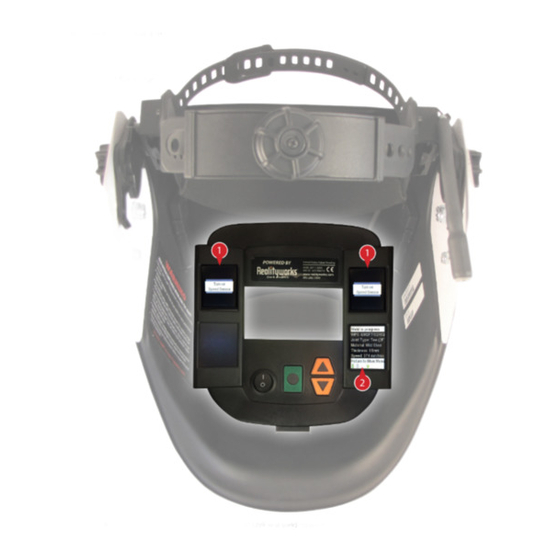
Page 6: Reference Guide To System Pieces
Reference Guide to System Pieces Use the images below as you walk through the set-up of your guideWELD LIVE Helmet and the calibration process. Speed Sensor 1. On/off button (back of Speed Sensor) 2. Binding button (back of Speed Sensor) 3. -
Page 7: Available Default Wps
Available Default WPS guideWELD® LIVE welding guidance system has 18 default WPS capability to weld for the tee joint, lap joint, and v-groove joint. The tee joint is in a 2F position, lap joint is in the 2F position, and the v-groove joint is in the 1G position. All base material is mild steel with several material thicknesses available in MIG and Stick. -
Page 8: Helmet Set-Up
Helmet Set-up View Reference Guide to System Pieces 7. Choose Thickness. (page 6) for button positioning and Press the menu select helmet guides. button to confirm 1. Turn on the Helmet and Speed Sensor 2. Look at the menu display, use navigation buttons to determine a choice on each of the following screens 8. -
Page 9: Calibration Process
Calibration Process NOTICE: The calibration process will need to be completed before each weld! The process includes Speed Sensor alignment and Angle Sensor calibration. The process is the same for Stick or MIG welding except when of using the Stick Calibration Fixture (for Stick welding only). - Page 10 Calibration Process (continued) Angle Sensor Calibration During calibration process and during weld, maintain a firm grasp on welding gun and Angle Sensor. For best results, keep Angle Sensor in the same location (between palm of hand/glove and welding gun) without movement.* 1.
-
Page 11: Angle Sensor Calibration (Continued)
Angle Sensor Calibration (continued) 5. Grasp the welding gun in the desired holding position, pivot handle down and hold 6. Press and release the calibration button on the Speed Sensor, the calibrating screen will display in the Helmet. Wait for first part of the calibration to complete before continuing 7. -
Page 12: Welding Icons/Guides
Welding Icons/Guides Welding Travel Angle Indicators (right top screen in the Helmet) Rotate Travel Angle Right Correct Rotate Travel Angle Left Based on the designated WPS, the Helmet will indicate if the travel angle is too far right, too far left or at the correct travel angle. The travel angle indicators’ (right arrow/left angle) size will increase when the weld moves farther away from acceptable welding travel angle and decrease as the weld moves toward the acceptable WPS standards. -
Page 13: Main Menu Setup
Main Menu Setup Under Setup, five areas are available for additional helmet programming. Setup Speed Sensor Diagnostics Firmware Precision Level Int’l Specs Set Precision Level: Metric/Imperial: Bind Turn Logging On/Off Versions Select 1, 2, 3 or 4 Select Metric or Imperial Language: Select English, Test Channels Helmet... -
Page 14: Speed Sensor (Setup)
Speed Sensor (setup) There are three levels of Speed Sensor: Bind, Test Channels and Identify. Read the information below for the steps and purpose of each level. Bind Each system goes through a binding process when it leaves the factory floor. Binding is when the Helmet of the guideWELD LIVE system is associated with the Speed Sensor. -
Page 15: Test Channels
Speed Sensor (setup continued) Test Channels Each system is set to a specific channel for the radio waves to communicate from the Speed Sensor to the Helmet. Setting the channel selection is done on the factory floor. The Speed Sensor and Helmet are not connected by any cabling; the unit sends radio waves from the Speed Sensor to the Helmet to tell the user what their speed is during an actual weld. -
Page 16: Diagnostics (Setup)
Diagnostics (setup) Diagnostics is used for troubleshooting purposes. There are four levels of diagnostics: Turn Logging On/Off, Helmet, Angle Sensor and Speed Sensor. Read the information below for the purpose of each level. These processes should only be done in a troubleshooting interaction. Turn Logging On/Off The SD card creates a log after each weld to show how the product functioned during that weld. -
Page 17: Firmware (Setup)
Firmware (setup) Firmware is used for software updates of the Helmet and Speed Sensor. There are four levels of Firmware: Versions, Update Helmet, Update Sensor and Update Flash Memory. Read the information below for the steps and purpose of each level. Versions Versions show the system software code and is used for troubleshooting for the Helmet, SPI, Sensor and SDC. -
Page 18: Update Sensor
Firmware (setup continued) Update Sensor Update Sensor is used to update the software code on the Speed Sensor. Update Sensor Instructions: 1. Turn on the Helmet 2. Insert SD Card into the Helmet 3. Go to the Main Menu, select Setup and press the menu select button 4. -
Page 19: Precision Levels (Setup)
Precision Levels (setup) Precision Level is the tolerance that is allowed for Work Angle, Travel Angle and Speed to be in comparison with the WPS. For example, if Work Angle is 45 degrees, precision level would allow a 45-degree mark miss by 2-3 degrees (42 degrees on the low end, 48 degrees on the high end) and still be acceptable for the guidance system. -
Page 20: Precision Levels (Setup Continued)
Precision Levels (setup continued) Change Default Precision Levels To change the default level, follow the steps below and enter the level each time the Helmet is used. After turning off the Helmet, it will default back to level 2 for Precision Level. Precision Levels Instructions: 1. -
Page 21: Troubleshooting
Troubleshooting Speed Sensor Speed Sensor needs to be turned on prior to using the system. Turn on the switch located on the back of the Speed Sensor. 1. “Turn on Speed Sensor” will display in the upper right and left screens 2. -
Page 22: Helmet Angle Sensor Calibration
Troubleshooting (continued) Helmet Angle Sensor Calibration The Angle Sensor will need to be calibrated before each weld. 1. If calibration screen 1 appears inside the Work Angle (right top screen) and Travel Angle (left top screen) screens, the Angle Sensor must be recalibrated (see calibration process) NOTE: Once Calibration has been completed, the calibration will stay for up to three minutes. -
Page 23: Angle Sensor
Troubleshooting Angle Sensor If the connection between the Helmet and the Angle Sensor is not communicating, it may be because of the Angle Sensor not being connected to the Helmet. 1. “Connect Hand Sensor” will display in the upper right and left screens 2. -
Page 24: Safety & Warnings
Safety & Warnings Only use guideWELD LIVE in a manner consistent with its intended purpose. • Observe Safety and Warnings that come with the included helmet (posted inside • of the helmet) Class 3R lasers are used in the guideWELD LIVE Speed Sensor. AVOID DIRECT EXPOSURE •...
Need help?
Do you have a question about the GUIDE WELD LIVE and is the answer not in the manual?
Questions and answers