
Related Manuals for Raymarine p70s


Summary of Contents for Raymarine p70s
- Page 1 / p70Rs PILOT CONTROLLER Installation instructions English (en-US) Date: 05-2021 Document number: 87424 (Rev 1) © 2021 Raymarine UK Limited...
- Page 3 Please check the website to ensure you have the latest documentation. Publication copyright Copyright ©2021 Raymarine UK Ltd. All rights reserved. No parts of this material may be copied, translated, or transmitted (in any medium) without the prior written permission of Raymarine UK Ltd.
-
Page 5: Table Of Contents
Contents Chapter 1 Important information..................7 TFT Displays ..........................8 Water ingress ..........................8 Disclaimer ........................... 8 Declaration of conformity......................8 Product disposal ........................8 Warranty registration ......................... 8 IMO and SOLAS ......................... 9 Technical accuracy ........................9 Chapter 2 Document and product information.............11 2.1 Document information ...................... - Page 6 Chapter 7 Technical specification................. 43 7.1 Technical specification ...................... 44 Chapter 8 Technical support ..................45 8.1 Raymarine product support and servicing ..............46 Viewing product information ....................47 8.2 Learning resources ......................47 Chapter 9 Spares and accessories ................49 9.1 Spares and Accessories....................
-
Page 7: Chapter 1 Important Information
Failure to do so could result in personal injury, damage to your vessel and/or poor product performance. • Raymarine highly recommends certified installation by a Raymarine approved installer. A certified installation qualifies for enhanced product warranty benefits. Register your warranty on the Raymarine website: www.raymarine.com/warranty... -
Page 8: Tft Displays
Raymarine. Raymarine is not responsible for damages or injuries caused by your use or inability to use the product, by the interaction of the product with products manufactured by others, or by errors in information utilized by the product supplied by third parties. -
Page 9: Imo And Solas
In addition, our policy of continuous product improvement may change specifications without notice. As a result, Raymarine cannot accept liability for any differences between the product and this document. Please check the Raymarine website (www.raymarine.com) to ensure you have the most up-to-date version(s) of the documentation for your product. -
Page 11: Chapter 2 Document And Product Information
Chapter 2: Document and product information Chapter contents • 2.1 Document information on page 12 • 2.2 Product overview on page 13 • 2.3 Compatible autopilot systems on page 16 Document and product information... -
Page 12: Document Information
Raymarine multifunction displays. Pilot controller commissioning and operation instructions For commissioning and operation instructions please refer to the p70 / p70s / p70R / p70Rs operation instructions. The p70 / p70s / p70R / p70Rs operation instructions (81402) can be downloaded from the Raymarine website: www.raymarine.com/manuals. -
Page 13: Document Illustrations
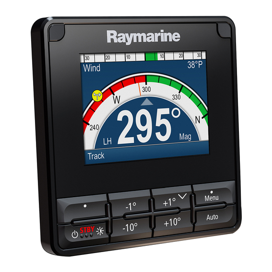
• Waterproof to IPx6 and IPx7. Controls Use the buttons to operate the display. Each button has multiple functions. Note: The p70s and p70Rs are pictured below. The p70 and p70R have the same control buttons as the p70s and p70Rs. Document and product information... - Page 14 • Turn counter-clockwise to decrease heading, move up through menu items or to decrease a numerical value. • Press the end of the rotary controller to select a menu option or save a change to a menu setting. The p70s also supports the following combination button presses: • –1° and –10°...
-
Page 15: Parts Supplied
Unpack your product carefully to prevent damage or loss of parts. Check the box contents against the list below. Retain the packaging and documentation for future reference. Suncover 2. Gunmetal bezel 3. p70s or p70Rs (p70s shown) supplied with keypad and black bezel fitted 4. Panel seal gasket 5. Documentation pack 6. Suppression ferrite Mounting fixings x 4 (M3x16 panhead pozi screws) 8. -
Page 16: Compatible Autopilot Systems
• www.raymarine.com/manuals 2.3 Compatible autopilot systems Your product is compatible with the following autopilot systems: Evolution™ autopilots (Connects via SeaTalkng ®) 2. SPX SmartPilot (Connects via SeaTalkng ®) 3. S1, S2 & S3 SmartPilot (Connects via SeaTalk ® to SeaTalkng ® converter E22158) -
Page 17: Chapter 3 Installation
Chapter 3: Installation Chapter contents • 3.1 Selecting a location on page 18 • 3.2 Product dimensions on page 20 • 3.3 Tools on page 20 • 3.4 Bezel removal on page 21 • 3.5 Removing the keypad on page 21 •... -
Page 18: Selecting A Location
3.1 Selecting a location Warnings and cautions Important: Before proceeding, ensure that you have read and understood the warnings and cautions provided in the Chapter 1 Important information section of this document. General location requirements Below are important requirements that need to be considered when choosing a suitable location to install your product. -
Page 19: Emc Installation Guidelines
For the viewing angles for your product refer to p.43 — Technical specification EMC installation guidelines Raymarine equipment and accessories conform to the appropriate Electromagnetic Compatibility (EMC) regulations, to minimize electromagnetic interference between equipment and minimize the effect such interference could have on the performance of your system Correct installation is required to ensure that EMC performance is not compromised. -
Page 20: Product Dimensions
3.2 Product dimensions The dimensions below must be considered when choosing a location for your product. • A: 115 mm (4.53 in) • B: 90 mm (3.54 in) • C: 110 mm (4.33 in) • D: 17.8 mm (0.7 in) •... -
Page 21: Bezel Removal
Note: (1) Drill bit size is dependent on the thickness and type of material that the unit is to be mounted on. 3.4 Bezel removal Prior to mounting the unit the bezel must be removed. Removing the bezel Note: Take care when removing the bezel. Only use a plastic pry tool (not supplied) to lever the bezel, attempting to use a metal tool may cause damage. -
Page 22: Mounting
1. Remove the bezel. 2. Using your fingers, grip the top edge of the keypad and pull it down and away from the unit. 3.6 Mounting Pre-mounting check The product is designed to be surface mounted. Before mounting the unit, ensure you have: •... -
Page 23: Mounting Diagram
Mounting diagram Note: The illustration above depicts mounting of a p70Rs. The mounting procedure for the p70s and p70Rs are the same. Mounting instructions 1. Ensure the selected location meets the location requirements found here: p.18 — General location requirements 2. -
Page 24: Fitting The Keypad
3.7 Fitting the keypad The keypad is held in place by tabs located on the top and bottom edge of the keypad. To fit the keypad correctly all of the tabs must be engaged. 1. Tilt the top edge of the keypad forwards and insert the bottom edge into the unit, ensuring the tabs line up with their respective slots. -
Page 25: Chapter 4 Connections
Chapter 4: Connections Chapter contents • 4.1 General cabling guidance on page 26 • 4.2 Connections overview on page 27 • 4.3 SeaTalkng ® power supply on page 27 • 4.4 Cable ferrite installation on page 32 • 4.5 SeaTalkng ® connection on page 33 •... -
Page 26: General Cabling Guidance
• Unless otherwise stated only use cables supplied by Raymarine. • Where it is necessary to use non-Raymarine cables, ensure that they are of correct quality and gauge for their intended purpose. (e.g.: longer power cable runs may require larger wire gauges to minimize voltage drop along the run). -
Page 27: Connections Overview
4.2 Connections overview Your product is supplied power and data using theSeaTalkng ® connector located on the back of the unit. Connector Connections • SeaTalkng ® backbone using a SeaTalkng ® spur cable. • NMEA 2000 backbone using SeaTalkng ® to DeviceNet adaptor cable (A06045) •... -
Page 28: Seatalkng ® Product Loading
The SeaTalkng ® power cable (A06049) is used to connect the SeaTalkng backbone to your chosen 12 V dc power supply. SeaTalkng ® product loading The number of products that can be connected to a SeaTalkng ® backbone depends on the current draw of each product and the physical length of the backbone cabling. -
Page 29: Seatalkng ® System Loading
• The information provided below is for guidance only, to help protect your product. It covers common vessel power arrangements, but does NOT cover every scenario. If you are unsure how to provide the correct level of protection, please consult an authorized Raymarine dealer or a suitably qualified professional marine electrician. - Page 30 Implementation — connection to distribution panel Waterproof fuse holder with 5 A inline fuse must be fitted (not supplied). 2. SeaTalkng ® power cable. 3. RF Ground connection point for drain wire. • Ideally, the SeaTalkng ® power cable should be connected to a suitable breaker or switch on the vessel's distribution panel or factory-fitted power distribution point.
- Page 31 Important: Observe the recommended fuse / breaker ratings provided in the product’s documentation, however be aware that the suitable fuse / breaker rating is dependent on the number of devices being connected. Implementation — direct connection to battery • SeaTalkng ®Where connection to a power distribution panel is not possible, the power cable may be connected to the vessel's battery..
-
Page 32: Cable Ferrite Installation
• For power cable extensions, a minimum wire gauge of 16 AWG (1.31 mm ) is recommended. For cable runs longer than 15 meters, you may need to consider a thicker wire gauge (e.g. 14 AWG (2.08 mm ), or 12 AWG (3.31 mm ) ). -
Page 33: Seatalkng ® Connection
4.5 SeaTalkng ® connection The p70s and p70Rs can be used to control Evolution™ and SPX autopilot systems. With either autopilot system the p70s / p70Rs is connected to the system using the same method, shown below. Note: An Evolution™ system that includes and ACU-100 or ACU-150 requires a dedicated 12 V dc power supply connected to the SeaTalkng ®... - Page 34 Expanded system example ACU unit (e.g.: ACU-200) 2. SeaTalkng ® instrument display (e.g.: i70s) 3. p70s / p70Rs Pilot controller (p70s shown) 4. SeaTalkng ® 5–way connector (A06064) 5. 12 V dc / 24 V dc power supply 6. EV sensor (e.g.: EV-1) Rudder reference transducer (M81105) 8.
-
Page 35: Seatalkng ® Cables
— SeaTalkng ® cables and accessories 4.6 SeaTalk connection The p70s and p70Rs can be used to control older SeasTalk ® autopilot systems. Connections to a SeasTalk ® network are made using a SeasTalk ® to SeasTalkng ® adaptor cable (not supplied). - Page 36 / p70Rs Pilot controller (p70s shown) 2. SeaTalkng ® to DeviceNet adaptor cable (e.g.: A06075) 3. DeviceNet T piece connector...
-
Page 37: Chapter 5 Maintenance
Chapter 5: Maintenance Chapter contents • 5.1 Routine equipment checks on page 38 • 5.2 Product cleaning on page 38 • 5.3 Cleaning the display screen on page 38 • 5.4 Cleaning the display case on page 38 • 5.5 Cleaning the sun cover on page 38 Maintenance... -
Page 38: Routine Equipment Checks
5.1 Routine equipment checks It is recommended that you perform the following routine checks, on a regular basis, to ensure the correct and reliable operation of your equipment: • Examine all cables for signs of damage or wear and tear. •... -
Page 39: Chapter 6 System Checks And Troubleshooting
Chapter 6: System checks and troubleshooting Chapter contents • 6.1 Troubleshooting on page 40 • 6.2 Power up troubleshooting on page 40 • 6.3 System data troubleshooting on page 41 • 6.4 Miscellaneous troubleshooting on page 41 System checks and troubleshooting... -
Page 40: Troubleshooting
If after referring to this section you are still having problems with your product, please refer to the Technical support section of this manual for useful links and Raymarine Product Support contact details. -
Page 41: System Data Troubleshooting
• Software corruption. In the unlikely event that the product’s software has become corrupted, try downloading and installing the latest software from the Raymarine website. refer to your Multifunction Display’s operation instructions for details on updating software for SeaTalkng devices. - Page 42 In the unlikely event that the product’s software has become corrupted, try downloading and installing the latest software from the Raymarine website. refer to your Multifunction Display’s operation instructions for details on updating software for SeaTalkng devices. 2. Check the data source for correct operation.
-
Page 43: Chapter 7 Technical Specification
Chapter 7: Technical specification Chapter contents • 7.1 Technical specification on page 44 Technical specification... -
Page 44: Technical Specification
7.1 Technical specification Nominal supply voltage 12 V dc Operating voltage range 9 V dc to 16 V dc (protected up to 32 V dc) Current 131 mA Power consumption 1.57 W LEN (Refer to the SeaTalk reference manual for further information.) Operating Temperature Range –20°C to 55°C (–4°F to 131°F) Storage Temperature Range... -
Page 45: Chapter 8 Technical Support
Chapter 8: Technical support Chapter contents • 8.1 Raymarine product support and servicing on page 46 • 8.2 Learning resources on page 47 Technical support... -
Page 46: Raymarine Product Support And Servicing
You can obtain this product information using diagnostic pages of the connected MFD. Servicing and warranty Raymarine offers dedicated service departments for warranty, service, and repairs. Don’t forget to visit the Raymarine website to register your product for extended warranty benefits: http://www.raymarine.co.uk/display/?id=788. United Kingdom (UK), EMEA, and Asia Pacific: •... -
Page 47: Viewing Product Information
5. Use the Up and Down buttons to cycle through the information. 8.2 Learning resources Raymarine has produced a range of learning resources to help you get the most out of your products. Video tutorials Raymarine official channel on YouTube: •... -
Page 49: Chapter 9 Spares And Accessories
Chapter 9: Spares and accessories Chapter contents • 9.1 Spares and Accessories on page 50 • 9.2 SeaTalkng ® cables and accessories on page 50 Spares and accessories... -
Page 50: Spares And Accessories
9.1 Spares and Accessories • A80353 — Black bezel for i70s / p70s / p70Rs • A80354 — Gunmetal bezel l for i70s / p70s / p70Rs • A80357 — Suncover for i70s / p70s • A80358 — Suncover for p70Rs 9.2 SeaTalkng ®... - Page 51 5. 1 x 2 m (6.6 ft) Power cable (A06049). Used to provide 12 V dc power to the SeaTalkng backbone. Evolution autopilot cable kit (R70160) consists of: 1 x 5 m (16.4 ft) Backbone cable (A06036). Used to create and extend the SeaTalkng backbone. 2.
- Page 52 1 x 2 m (6.6 ft) Power cable (A06049). Used to provide 12 V dc power to the SeaTalkng backbone. 2. 1 x 1 m (3.3 ft) Spur cable (A06039). Used to connect a device to the SeaTalkng backbone. 3. 1 x 1 m (3.3 ft) NMEA 0183 VHF stripped-end (2 wire) to SeaTalkng adapter cable (A06071). Used to connect an NMEA 0183 VHF radio to the SeaTalkng backbone via the NMEA 0183 VHF to SeaTalkng converter.
- Page 53 4. SeaTalkng to stripped-end spur cables (Connects compatible product that do not have a SeaTalkng connector such as transducer pods): • 1 m (3.3 ft) SeaTalkng to stripped-end spur cable — A06043 • 3 m (9.8 ft) SeaTalkng to stripped-end spur cable — A06044 5.
- Page 54 5. Backbone terminator (A06031). Terminators must be fitted to both ends of the SeaTalkng backbone. 6. Spur blanking plugs (A06032). Used to cover unused spur connections in 5–way blocks, T-piece connectors, or the SeaTalk to SeaTalkng converter. Spur connector right angled elbow (A06077). Used in confined spaces where a straight spur cable will not fit.
- Page 55 10. (0.4 m (1.3 ft) DeviceNet (female) to stripped-end adaptor cable (E05026). 11. (0.4 m (1.3 ft) DeviceNet (male) to stripped-end adaptor cable (E05027). Spares and accessories...
-
Page 57: Appendix A Supported Nmea 2000 Pgn List
• 126464 — PGN Transmit and Receive List (Receive / Transmit) • 126996 — Product Information (Receive / Transmit) Raymarine® provides field programmability of the Device and System Instances within PGN 60928 which can be commanded via use of PGN 126208 as required by the latest NMEA 2000 standard. - Page 59 Index Interference RF................. 19 Accessories SeaTalkng adaptor cables ........54 SeaTalkng backbone cables .......53 SeaTalkng cables ..........50 Keypad fitting ............24 SeaTalkng connectors .........53 Keypad removal ............21 SeaTalkng kits ............ 50 SeaTalkng Power cables ........53 SeaTalkng spur cables ........52 Applicable products ..........13 Location requirements ..........
- Page 60 Connecting cables ..........27 Connectors ............53 Kits ..............50 LEN ..............28 Load equivalency number ........28 Power............27–28 Power cables ............53 Spur cables ............52 System loading ............29 SeaTalkng cables ........... 50 SeaTalkng system ........... 33 Service Center............46 SmartPilot ..............16 Software version............15 SPX ................
- Page 62 Raymarine Marine House, Cartwright Drive, Fareham, Hampshire. PO15 5RJ. United Kingdom. Tel: +44 (0)1329 246 700 www.raymarine.com a brand by...
Need help?
Do you have a question about the p70s and is the answer not in the manual?
Questions and answers