Table of Contents
Advertisement
Quick Links
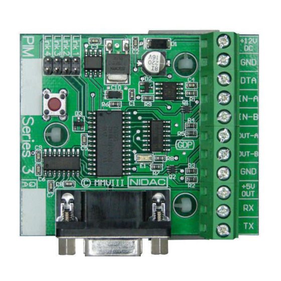
PIM
Presco™ Interface Module
"Series 3"
Revision h
st
Installation Manual 1
N761
INTRODUCTION
The Presco™ Interface Module (PIM) can be used to
convert commonly used data formats to Nidac
Presco™, RS232, Clock & Data or Wiegand format
data.
FEATURES
•
Converts from Wiegand, RS232, Nidac Presco™,
Clock & Data (Magnetic Card) or Dallas iButton™
(commonly referred to as Silicon Key) format.
•
Converts to Nidac Presco™, RS232, Clock & Data
(Magnetic Card) or Wiegand format.
•
Can convert to or from Wiegand with up to 64 bits
of data, including up to 32 bit site code plus
optional start and end parity bits.
•
User programmable site code when converting to
Wiegand.
•
Reads up to 64 bits from Dallas iButton™ user
memory or 56 bits from factory ID.
•
Reads up to 32 characters or digits from Track 1, 2
or 3 Clock & Data (magnetic card) format input.
•
User programmable settings using standard
Presco™ keypad or via RS232 link (software for
RS232 programming is available from Nidac's
website www.nidac.com).
•
Compatible with all current Nidac Presco™
encoders and decoders.
SPECIFICATIONS
Voltage:
10 to 15 Volts D.C.
Current:
30mA max (plus 5V
output draw).
Dimensions:
66mm x 67mm x
23mm.
Weight:
45gms.
Wiegand
Pulse Width:
50s
Pulse Separation:
2ms
RS232:
Baud Rate:
300, 600, 1200, 2400,
4800, 9600, 19200,
38400, 57600 or
115200 bps.
Data bits:
8
Parity:
None, Odd or Even.
Handshaking:
Hardware or None.
TERMINAL DESCRIPTIONS
+12V DC
GND
DTA
IN-A
Edition
IN-B
OUT-A
OUT-B
+5V OUT
RX
TX
CABLING DISTANCES TO PIM
Device
RS232
iButton™
iButton™
Clock &
Data
Wiegand
Presco™
PSC16 or
PRE keypad
Presco™
PSE keypad
without
backlighting
Presco™
PSE keypad
with
backlighting
Presco™
PRO2410,
PSC16 or
PSR16
proximity
reader
Presco™
VR43 or
VR62
keypad.
NOTE all distances are based on a supply voltage of
12.0V D.C. at the PIM.
The positive D.C. power input.
The Ground (or Negative) power input.
This is also a common reference
connection for all devices connected to
the PIM. i.e. all devices connected to the
PIM require their GNDs to be connected
together.
Presco™ data input/output.
Input A (Wiegand D0, Clock & Data RDP
or iButton™).
Input B (Wiegand D1 or Clock & Data RCP).
Output A (Wiegand D0 or Clock & Data
RDP).
Output B (Wiegand D1 or Clock & Data
RCP).
A 5 Volt D.C. power output for powering
connected equipment (100mA. max.).
The RS232 Receive input (DO NOT USE
THIS TERMINAL WHEN USING THE
RS232 DB9 CONNECTOR!).
The RS232 Transmit output.
Cable type
7/020 shielded or CAT 5
UTP cable.
4 core (3 wires) required for
no handshaking.
6 core (5 wires) required for
hardware handshaking.
Telephone cable
Must be unshielded twisted
pair.
2 core for reader only.
4 core for reader + LED
control.
CAT 5 cable.
Use 1 pair for reader, any
other wires for LED control.
7/020 shielded cable.
4 core for reader only.
6 core for reader + LED
control.
Ground the shield at PIM end
only.
7/020 shielded cable.
4 core for reader only.
6 core for reader + LED
control.
Ground the shield at PIM end
only.
7/020 unshielded cable.
2 core (figure 8) for data
only, no LED control.
4 core for PSK16/PRE with
LED control.
2 core (figure 8) 7/020
unshielded cable.
4 core 7/020 unshielded
cable.
NOTE decreased distance is
due to extra current drawn by
backlighting.
4 core 14/020 unshielded
cable.
4 core 7/020 unshielded
cable.
4 core 14/020 unshielded
cable.
NOTE decreased distance is
due to extra current drawn by
powering the reader.
4 core 7/020 unshielded
cable.
4 core 14/020 unshielded
cable.
NOTE decreased distance is
due to extra current drawn by
powering the keypad.
1
LINK SETTINGS SUMMARY
Links
Input
Clock & Data
RS232
Clock & Data
Presco™
RS232
Presco™ DLOG
(from PACDL)
RS232
Presco™
Dallas iButton™
Use this setting to reset the memories
Max
to defaults when unit is powered up with
length
10m
Dallas iButton™
DO NOT USE. Reserved for future use.
10m
Wiegand
RS232
Wiegand
100m
Presco™
100m
Wiring Diagrams
From Presco™ PSK16 (shown) or PRE
100m
1000m
From Presco™ PRO2410 (shown), PSC16 or PSR16
1000m
500m
1000m
From Presco™ VR43 (shown) or VR62
350m
800m
350m
800m
Output
Presco™ (PAC1/PAC2),
Wiegand and RS232
Clock & Data
Presco™ (KCx or PDA),
Clock & Data and RS232
Clock & Data
Presco™
RS232
Presco™ DLOG
(to PAC1 or PAC2 for use
with PIM-PAC software)
RS232
Presco™ (PAC1/PAC2),
Wiegand and RS232
program button depressed.
Presco™ (KCx or PDA),
Clock & Data and RS232
Presco™ (PAC1/PAC2),
Wiegand and RS232
Wiegand
Presco™ (KCx or PDA),
Clock & Data and RS232
Wiegand
Advertisement
Table of Contents

Summary of Contents for Nidac Presco PIM 3 Series
- Page 1 Use 1 pair for reader, any (commonly referred to as Silicon Key) format. Presco™ Wiegand other wires for LED control. • Converts to Nidac Presco™, RS232, Clock & Data Clock & 7/020 shielded cable. 100m (Magnetic Card) or Wiegand format. Data 4 core for reader only.
- Page 2 Presco™ to Clock & Data From Wiegand Reader To Wiegand Input Controller Links 3 & 4 ON The Presco™ data can be converted to 1 to 32 digits of track 1, 2 or 3 format Clock & Data. Please refer to the CLOCK &...
- Page 3 The software for programming the PIM via RS232 is characters. separator will be converted to the user code. When no available from Nidac’s website www.nidac.com in the Further settings are available for RS232 data. Please separator if sent all digits will be converted to the user Downloads->Presco->Presco Software section.
- Page 4 64 bits of data or 8 Note that using this setting requires a high milliseconds has elapsed since it received its understanding of Wiegand data. Nidac will only iButton™ SETTINGS MEMORIES last data bit. All these bits will be treated as the offer limited support for this feature.
Need help?
Do you have a question about the Presco PIM 3 Series and is the answer not in the manual?
Questions and answers