Table of Contents
Advertisement
Quick Links
MFT-40
M
F
T
y
irst
ransceiver
40 Meters DSB Transceiver Kit
Assembly manual
Last update: June 1, 2017
ea3gcy@gmail.com
www.ea3gcy.com
:
Most recent updates and news at
MFT-40 DSB Transceiver kit
Thanks for constructing the
Have fun assembling it and enjoy QRP!
73 Javier Solans, ea3gcy
MFT-40 DSB Transceiver Kit
Page 1
Advertisement
Table of Contents

Related Manuals for EA3GCY My First Transceiver MFT-40


Summary of Contents for EA3GCY My First Transceiver MFT-40
- Page 1 Assembly manual Last update: June 1, 2017 ea3gcy@gmail.com www.ea3gcy.com Most recent updates and news at MFT-40 DSB Transceiver kit Thanks for constructing the Have fun assembling it and enjoy QRP! 73 Javier Solans, ea3gcy MFT-40 DSB Transceiver Kit Page 1...
-
Page 2: Specifications
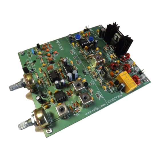
INTRODUCTION MFT-40 The MFT-40 “My First Transceiver” is a simple, low-cost DSB (double sideband) transceiver similar to the famous “Beach-40”, “Micro-40” by VK3YE, “Wee Willy” by VA3IUL, etc. However, the MFT has improved both the receive and transmit characteristics, and its kit assembly puts the project within the reach of radio circuit builders of any level. -
Page 3: Tips For First Time Builders
TRANSMITTER: RF output: 3W@12V, 4W@13.8V. Second harmonic output: -40dB below the fundamental frequency. Other spurious signals: all signals -45dB or better below the fundamental frequency. Carrier suppression: better than -20dB. T/R switching: Relay. Microphone type: electret. RECEIVER: Type: DC Direct Conversion. Front end: Triple tuned circuit. - Page 4 To solder properly, you must use a high-quality solder for electronics use and the correct type of iron. Use a small soldering iron with a fine, pointed tip. The soldering iron should be about 30 watts (if it is not thermostatically controlled).
-
Page 5: Parts List Sorted By Value/Quantity
PARTS LIST SORTED BY VALUE/QUANTITY Resistor list Value Checked Ref. Identified R31, R32 brown-black-gold brown-black-black R1, R10 red-red-black yellow-violet-black R6, R21, R23, R26 brown-black-brown red-red-brown R14, R15, R28 yellow-violet-brown R2, R13, R20, R25, R30, R34 brown-black-red R8, R19, R24, R27 yellow-violet-red blue-gray-red R3, R4, R7, R11, R18... - Page 6 Semiconductor list Type Checked Ref. Identified Transistors BC547 Q1, Q2 BC547 P2222 2222 BD135 BD135 2SC2078 Q5 (heatsink + washer + mica spacer) C2078 Integrated circuits LM741 LM741CN or UA741 SA/NE602 IC1, IC6 SA602AN or NE602AN LM386 LM386N-1 78L06 IC4, IC7 MC78L06 78L08 MC78L08...
- Page 7 LIST OF INDIVIDUAL COMPONENTS The shaded rows are the receiver parts; the other rows are the components of the transmitter. The receiving block contains the VFO and can operate independently even if the transmitter is not built; however, the transmitter needs the receiver to work.
- Page 8 82 or 82J Rx passband J-8/9 22 or 22J Rx passband J-8/9 100n 104 or 0.1 Rx Mix 100n 104 or 0.1 Rx Mix L-8/9 100n 104 or 0.1 Rx Mix L-4/5 10uF 10uF electrolytic Rx Mix 100n 104 or 0.1 Rx Mix 100n 104 or 0.1...
- Page 9 Crystals Checked Ref. Frequency Ident./Comment Circuit section Located 7.200 ceramic resonator K/L-1/2 L-1/2 Semiconductors Checked Ref. Type Ident./Comment Circuit section Located Transistors BC547 BC547 Rx Mute H-8/9 BC547 BC547 P2222 PN2222 Pre Diver BD135 BD135 Driver 2SC2078 2SC2078 Output Amp IC's SA/NE602 SA602AN or NE602AN...
- Page 10 143-QUADRANT COMPONENT LAYOUT MAP MFT-40 DSB Transceiver Kit Page 10...
-
Page 11: Recommended Assembly Sequence
ASSEMBLY You can use the “individual parts list” or the “value/quantity parts list.” Using the “value/quantity parts list” is the quickest way to mount components since all the circuit board components of the same value or type can be placed one after the other. However, you will need the “individual parts list” to know how each component is identified and its location on the circuit board. - Page 12 Axial Inductors L5 and L8 These components look like thick-bodied resistors and the body is colored blue or green. In its interior there is a small coil wound on a ferrite core. Refer to the parts list to select the correct component for each location.
- Page 13 D4 is a zener diode. It is marked 9V1 D2 (bias limiter) 1N4007 or 1N4001 diode is black with a gray band. This is placed vertically as shown in the picture (about 10-12mm high). The end with the gray band goes to the hole marked GND DV is the varicap diode in SMD format that is already soldered.
- Page 14 Pin "headers" To build the complete transceiver you must place pins in: MIC(3), 12-14V(2), ANT(2), SPEAK(2), EXT- VFO(2), J1(2) Note: If you want to build only the RX section, then place these pins: +V(1), +VRX(2), SPEAK(2), RX- ANT(2) EXT-VFO(2), and J1(2). Turn the board over and insert and hold the header in place, using a “jumper”...
- Page 15 Integrated circuits The component outline for the IC on the circuit board has a “U” shaped notch on one end, indicating the end at which pin 1 of the IC is located. There is a similar notch on one end of the sockets. This should be oriented over the "U"...
- Page 16 Resonator (or optional crystals) Install X1resonator marked as 7200 (or 7370 optional). Relay Install relay RL1; it can only be mounted in one position. Make sure that the body of the relay lies flat against the circuit board. ...
- Page 17 Toroidal transformer L7 L7 is an impedance matching transformer. An FT37-43 is used (black toroid with 9.5mm/0.375in OD). It has a 10-turn primary and a 3-turn secondary. - Take 17cm (7.5”) of 0.5mm diameter enameled wire and wind ten (10) turns on a black FT37-43 toroidal core.
- Page 18 IMPORTANT: Wind the toroid exactly as shown in the pictures. You must pay attention to number of turns as well as to the direction of the winding. Toroidal transformer L9 L9 is an impedance matching transformer with a bifilar winding. An FT37-43 is used (black toroid with 9.5mm/0.375in OD).
- Page 19 - Before beginning to wind, leave 15-20mm of wire, measured from the end of the wires to the outer edge of the toroid. Now wind eight (8) turns on the toroid. Remember: Count one turn for every time the wire passes through the center of the toroid. - Spread the turns evenly around the toroid.
-
Page 20: Adjustments And Tests
Jumper J1 (tuning ranges) The Jumper J1 allows choose a part of the double varicap diode or both at the same time. The approximate coverage (ceramic resonator 7200) is as follows: J1 Not Placed: from 7.093 to 7.155MHz. J1 Placed: from 7.055 to 7.130MHz. - Page 21 Adjustment of the RX pass band, L1, L2 and L3 Note: For this adjustment you will need an “alignment” tool suitable for this type of coils; if you use a screwdriver, you risk of breaking the core of the coil. With an antenna connected to the transceiver, sequentially adjust L1, L2 and L3 until obtaining the maximum level of noise in the speaker.
-
Page 22: Useful Notes
C29 and C30 should be the same value). With small values the frequency will rise and high values will decrease. For these experiments use good quality NPO, styroflex or similar capacitors. EA3GCY Kits does not respond to possible faults caused by modifications. ... - Page 23 The connection scheme is very simple: Or you can build your own handheld microphone with the micro electret capsule included in the kit and a pushbutton for PTT (not included): Mic “home made” Handheld mic optional (ea3gcy.com) MFT-40 DSB Transceiver Kit Page 23...
-
Page 24: If Your Kit Does Not Work After Assembly
- If you decide that technical assistance is needed, you are welcome to send an email to ea3gcy@gmail.com. As a last resource, you may send the kit in for repair; however, I will have to charge for any repairs done, although I will try to keep the cost as moderate as possible. -
Page 25: Limited Warranty
Please, BEFORE returning a product, request instructions by email at: ea3gcy@gmail.com Javier Solans, EA3GCY, warrants this device to function according to the specifications, provided that it is assembled and adjusted as described in this documentation, and used correctly according to all provided instructions. - Page 26 SCHEMATIC MFT-40 DSB Transceiver Kit Page 26...
- Page 27 WIRING for TX + RX full use RX+TX Transceiver use (normal use) Note that if you use the RX along with the TX, you do not have to connect anything in “VFO-TX”, “+V”, “+VRX”, “+VTX” and “RX-ANT” terminals. The "VFO-TX" and "VTX" terminals are arranged to use a different transmitter. MFT-40 DSB Transceiver Kit Page 27...
- Page 28 WIRING (To use RX only) MFT-40 DSB Transceiver Kit Page 28...
- Page 29 The MFT-40 transceiver wiring is very simple, as long as you remember that: - For the antenna connection use a thin, RF-rated coaxial cable such as RG-174 or similar. - If you install the potentiometers off the circuit board, you should use short, as the mechanical stability is very important.
Need help?
Do you have a question about the My First Transceiver MFT-40 and is the answer not in the manual?
Questions and answers