Table of Contents
Advertisement
Quick Links
Advertisement
Table of Contents

Summary of Contents for TELEDYNE OLDHAM SIMTRONICS Everywhereyoulook ВМ 25A
- Page 1 USER MANUAL BM 25A/AW AREA GAS MONITOR NPB25AEN-Revision D.0...
- Page 2 User Manuals in other languages are available on Website https://teledynegasandflamedetection.com Copyright April 2021 by TELEDYNE OLDHAM SIMTRONICS S.A.S. All rights reserved. No reproduction of all or part of this document, in any form, is permitted without the written consent of TELEDYNE OLDHAM SIMTRONICS S.A.S.
- Page 3 It is important that you read this entire manual carefully and thoroughly. The extent of our responsibility • TELEDYNE OLDHAM SIMTRONICS shall not be held responsible for any damage to the equipment or for any physical injury or death resulting in whole or in part from the...
- Page 4 BM 25A/AW AREA GAS MONITOR USER MANUAL IMPORTANT: Read and understand this manual before operating. WARNING: SERVICING THE UNIT OR CHANGING THE BATTERIES MUST ONLY BE DONE IN AN AREA KNOWN TO BE NONHAZARDOUS. Prior to each day’s use, a bump test should be performed. If the instrument does not pass the bump test, a full calibration is recommended.
- Page 5 BM 25A/AW AREA GAS MONITOR USER MANUAL The BM 25A/AW is CSA certified according to the Canadian Electrical Code for use in Class I, Division 1 and Class I, Zone 1 Hazardous Locations within an ambient temperature range of -20°C to +55°C. CSA has assessed only the combustible gas detection portion of this instrument for performance according to CSA Standard C22.2 No.
- Page 6 BM 25A/AW AREA GAS MONITOR USER MANUAL NPB25AEN Revision D.0...
-
Page 7: Table Of Contents
BM 25A/AW AREA GAS MONITOR USER MANUAL Table of Contents Introduction ..................1 General information ..................1 Product Overview ..................... 2 Additional equipment ..................4 Connections ......................5 Gas sensors......................6 LCD Display ......................7 Visual alarm ......................8 Audible alarm ..................... 8 Sampling system .................... - Page 8 BM 25A/AW AREA GAS MONITOR USER MANUAL Maintenance ................... 33 Accessing maintenance menus..............33 Program menu ....................34 Sensor calibration menu ................. 35 Auto-adjustment menu ................... 36 Date and time management menu ............36 Radio communication menu ............... 36 MAC List menu ....................36 Exit menu .......................
-
Page 9: Introduction
BM 25A/AW AREA GAS MONITOR USER MANUAL Introduction General information The BM 25A/AW is a portable gas monitor that can be used in explosive gas atmospheres. It provides simultaneous detection of up to five gases present in the air by means of sensors specific to each risk to be evaluated (under-oxygenation, presence of combustible or toxic gases). -
Page 10: Product Overview
BM 25A/AW AREA GAS MONITOR USER MANUAL Product Overview Figure 2: Product Overview NPB25AEN Revision D.0... - Page 11 BM 25A/AW AREA GAS MONITOR USER MANUAL Ref. Description See page Carrying handle LED alarm indicator (visual warning for gas alarms, transferred alarms and faults) • Low Alarm: slow flash (1 Hz) • High Alarm: rapid flash (2 Hz) • Alarm Transfer: very slow flash (0.5 Hz) •...
-
Page 12: Additional Equipment
BM 25A/AW AREA GAS MONITOR USER MANUAL Additional equipment Figure 3: accessories Ref. Description See page Sensors Cover for use with aspirated versions (*) Calibration cup for use with manual sampling system or for sensors calibration Intrinsically Safe Trickle Charge Kit (provided with cables) Calibration/Sample tubing Communication Adaptor Universal charger 110/230 VAC... -
Page 13: Connections
BM 25A/AW AREA GAS MONITOR USER MANUAL Connections 1.4.1 Charging port connection (red ring) • Connection TELEDYNE OLDHAM SIMTRONICS universal charger (110/230 VAC) or charger for vehicle (12/30 VDC) • Pin 1: V- charge • Pin 4: V+ charge Connection prohibited in hazardous area. Unused connectors must be equipped with their protective cap. -
Page 14: Gas Sensors
BM 25A/AW AREA GAS MONITOR USER MANUAL 1.4.4 Dry logic inputs (yellow ring) • Pin 2: logic input for alarm transfer • Pin 5: logic input for alarm acknowledgement • Pin 7: common ground Unused connectors must be equipped with their protective cap. -
Page 15: Lcd Display
BM 25A/AW AREA GAS MONITOR USER MANUAL Ref. Description Combustible gas sensor (0 to 100% LEL) Mini sensors for toxic gases or the 1 year O sensor Mini sensors for toxic gases or the 1 year O sensor Medium sensors for: •... -
Page 16: Visual Alarm
BM 25A/AW AREA GAS MONITOR USER MANUAL The following information is displayed: • Up to 5 gas measurements along with gas names and units • Maintenance call for calibration • Date and time • Minimum and maximum values (peak) measured •... -
Page 17: Installation And Connections
BM 25A/AW AREA GAS MONITOR USER MANUAL Installation and Connections Power supply 2.1.1 General Information Power is supplied to the gas monitor through an interchangeable and rechargeable battery pack (NiMH 7.2 V / 9 Ah). Under normal usage conditions and no radio communication, the battery life ranges from 40 to 170 hours depending on the configuration (100 hours under typical configuration: diffusion mode with 1 catalytic or 1 infrared sensor and 2 electrochemical sensors). - Page 18 (catalytic, infrared, PID) or when the pump is continuously running. Only intrinsically safe power supplies provided by TELEDYNE OLDHAM SIMTRONICS can be used. Insert the male connector (Figure 11, ref. 6) from the trickle charger (ref. 1 and 3) into the port with a black ring that is located on the left side of the BM 25A/AW (ref.
-
Page 19: Alarm Transfer
BM 25A/AW AREA GAS MONITOR USER MANUAL Figure 11: trickle charger connection Alarm Transfer By connecting the output of a BM 25A to the input of another BM 25A, and so on, it is possible to transfer alarms from instruments to instruments. This configuration is particularly useful for perimeter monitoring. -
Page 20: Connection Of A Manual Call Point
BM 25A/AW AREA GAS MONITOR USER MANUAL Connection of a manual call point By connecting a manual call point to the input of a BM 25A/AW, it allows the user to fire the local audible and visible alarm in order to alert of an immediate danger (fire, man down, evacuation, etc.). -
Page 21: Operation
• Before displaying current measurements, the BM25 A/AW performs visual and audible tests during a few seconds and then displays: - The TELEDYNE OLDHAM SIMTRONICS logo, - The software revision and the serial number, - The alarm thresholds set for each measurement channel. -
Page 22: Gas Monitor Positioning
BM 25A/AW AREA GAS MONITOR USER MANUAL Step 1: Switch the instrument on • Press and hold the Acquit button (ref. 1). Press the Enter button (ref. 2) to switch the instrument on. • Release both buttons. • When warm-up is complete, the BM 25A/AW displays the list of different gases. -
Page 23: Aspirated Mode (With Pump Option)
BM 25A/AW AREA GAS MONITOR USER MANUAL Aspirated mode (with pump option) Remote sensing is possible with the internal electric pump option, or by using a hand aspirator. Sampling probes (rigid, semi-rigid or telescopic) and sampling tubing are not antistatic. The user must take the necessary precautions to avoid electrostatic discharges. -
Page 24: Measurements
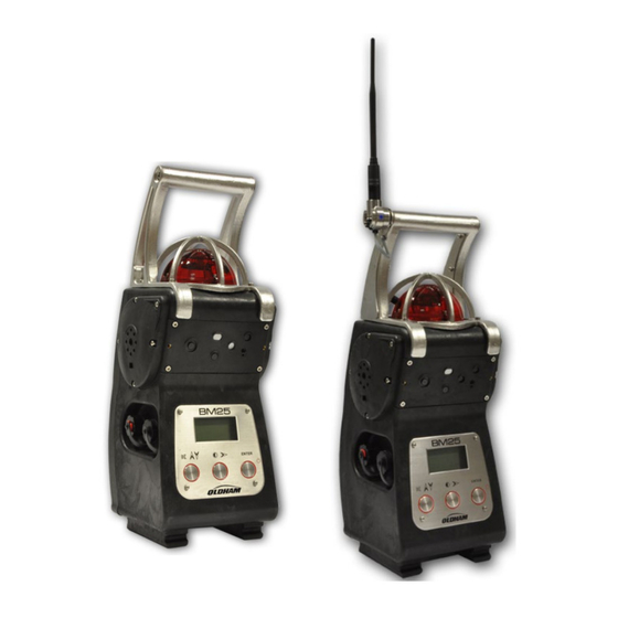
BM 25A/AW AREA GAS MONITOR USER MANUAL 3.4.2 Using a manual pump Figure 16: positioning the sensors cover (BM 25A/AW non-equipped with an electric pump) • Place and screw the cover over the sensors (Figure 16: positioning the sensors cover ■... - Page 25 BM 25A/AW AREA GAS MONITOR USER MANUAL Figure 17: on the left side, 4-gas monitor with no radio communication. On the right side, 3-gas monitor with radio ON. Combustible gas concentration measurements can be affected by high or low oxygen concentrations.
-
Page 26: Alarms
BM 25A/AW AREA GAS MONITOR USER MANUAL Roundsman function Roundsman If the function has been activated, a list of names can be programmed using 2100 software. This list can be viewed at any time by using the front keys on the device. To select a location or a user, follow these steps: •... - Page 27 BM 25A/AW AREA GAS MONITOR USER MANUAL The display will also indicate the alarm message(s) (ALARM 1, ALARM 2, AL. TRANSFER, STEL, TWA, mini, etc.) as well as the gas measurement. In alarm mode, the monitor will display the peak values (min or max depending on the gas type) until acknowledgement button pressed.
- Page 28 BM 25A/AW AREA GAS MONITOR USER MANUAL Normal operating conditions can be restored by power cycling the BM 25A/AW. This operation must be performed outside the hazardous area. Out of range • Negative Zero Drift (reading below -20% of full scale). This fault is automatically resettable.
-
Page 29: Data Transfer
Special Instructions for monitor. These parameters are mentioned in the paragraph use in explosive atmospheres on page 55. TELEDYNE OLDHAM SIMTRONICS shall not, in any event, be liable for failure to follow regulations. Data transfer The BM 25A/AW stores gas measurements, alarm and fault events. Those data can later be... -
Page 30: Switching Off
BM 25A/AW AREA GAS MONITOR USER MANUAL Switching off • To switch the instrument off, press the Enter button (ref. 1) located on the front plate, for 3 seconds. • The instrument display starts a countdown from 3 to 1 Enter before it asks to confirm. -
Page 31: Wireless Version
BM 25A/AW AREA GAS MONITOR USER MANUAL Wireless Version This product complies with FCC Maximum Permissible Exposure (MPE) requirements when used with an approved antenna and the antenna is at least 20cm away from the user. Use of the product closer than 20cm may exceed the MPE limits. Use of any antenna other than approved antennas will invalidate the certification of the product. - Page 32 BM 25A/AW AREA GAS MONITOR USER MANUAL BM 25 4.1.1 Mode When in BM 25 mode, BM 25AWs send information regarding gas alarm and fault status. Once a BM 25AW is in gas alarm, the alarm is repeated on all other BM 25AWs on the same network.
- Page 33 BM 25A/AW AREA GAS MONITOR USER MANUAL Gas alarm Transfer In the event one BM 25AW goes into a gas alarm, all secondary BM 25AWs will display « Al. Transfert » as shown below. Press the “acquit” button to silence the audible alarm. The BM 25AW strobe will continue to flash until the alarm event has ended.
- Page 34 BM 25A/AW AREA GAS MONITOR USER MANUAL Two-way communication Figure 24 : In the example above, BM 25AWs E and F are the last links between the controller and the rest of the network. If communication between BM 25AW F and MX 40 fails, then BM 25AW E continues to provide communication between the BM 25AW network and the controller.
-
Page 35: Start-Up
BM 25A/AW AREA GAS MONITOR USER MANUAL Start-up From the Maintenance menu (see Chapter 5), choose Wireless. Leave it to 'OFF' if you do not BM 25 want to activate the radio function. Select ' ' or 'Controller' according to the chosen operation mode (see above). - Page 36 BM 25A/AW AREA GAS MONITOR USER MANUAL Thereafter, in normal operation, each BM 25AW sends its information over the network every ten seconds. If a BM 25AW goes into gas alarm or fault condition, then the information is BM 25 mode immediately sent without waiting ten seconds.
-
Page 37: Self-Healing
BM 25A/AW AREA GAS MONITOR USER MANUAL 4.2.2 Removing a BM 25AW from an existing network In BM 25 mode • turn the unit off • or deactivate the radio module from the maintenance menu. In both cases, before communication stops, the BM 25AW broadcasts a last message to inform the other BM 25AWs on the same network that it will be removed. - Page 38 BM 25A/AW AREA GAS MONITOR USER MANUAL In the example above, BM 25AW (unit D) is the only communication link between A, B, C and E, F, G. If BM 25AW (unit D) had a fault (low battery for instance) or if an obstacle were to disrupt communication between D and E or D and B, then all BM 25AWs would report a fault failure (steady flashlight according to case No.
- Page 39 BM 25A/AW AREA GAS MONITOR USER MANUAL IMPORTANT : • The two groups run independently and alarm or failure events from one group cannot be transferred to the other group. • When the obstacle (the truck in our example) is gone, the communication between E and D resumes automatically without the need to restart identification.
-
Page 40: Mac List Menu
BM 25A/AW AREA GAS MONITOR USER MANUAL Mac list menu BM 25 NOTE : This section covers the mode only. Available from the Maintenance menu (see 0), the « MAC List » menu allows the user from any BM 25AW belonging to the network to get the MAC address of each BM 25AW on the network and its particular... -
Page 41: Maintenance
USER MANUAL Maintenance Gas monitors are safety instruments. Recognizing this fact, TELEDYNE OLDHAM SIMTRONICS recommends that a functional test be performed on every portable gas monitor prior to each use. A functional test involves injecting a gas of sufficient concentration at the sensor level to trigger pre-set alarms. -
Page 42: Program Menu
If the Other combustible gas to be detected is not in this list, you can use the window by selecting a coefficient provided by TELEDYNE OLDHAM SIMTRONICS (contact us). NPB25AEN Revision D.0... -
Page 43: Sensor Calibration Menu
BM 25A/AW AREA GAS MONITOR USER MANUAL Molecular Vapor Coef. / Recom- Abbreviat formula density mended calgas (French) Acetone 2.15 % 13 % But/Prop Acetylene 1.5 % 100 % But/Prop Butane 1.5 % 8.5 % 2.13 But/Prop Ethanol 3.3 % 19.0 % But/Prop Ethylene... -
Page 44: Auto-Adjustment Menu
When battery is low, the user is notified with a message before losing all stored data. The battery must then be replaced. This operation should only be performed by TELEDYNE OLDHAM SIMTRONICS or TELEDYNE OLDHAM SIMTRONICS approved personnel. Radio communication menu This menu allows the user to: •... -
Page 45: Com2100 Software
BM 25A/AW AREA GAS MONITOR USER MANUAL COM2100 software Subject This software is for settings and service purpose. It features: • Channels settings • Diagnostics in case of failure • Instrument settings • Sensors calibration • Calibration and Control certificates •... -
Page 46: Maintenance Menu
BM 25A/AW AREA GAS MONITOR USER MANUAL Maintenance menu Follow the steps below: • From the main list of menus, access the Maintenance menu. Options are: • Maintenance Program Figure 38: menu : see page 38 • Calibration : see page 39 •... - Page 47 BM 25A/AW AREA GAS MONITOR USER MANUAL Alarm settings Channel selection - Select the channel from the dropdown list ( Figure 39): • Edit alarm threshold values • Click Alarm validation to save your settings. Reference Gas settings • Access is password protected. Select the channel fitted with the catalytic sensor (Channel selection, see Figure 39).
- Page 48 BM 25A/AW AREA GAS MONITOR USER MANUAL TELEDYNE OLDHAM SIMTRONICS recommends using pure gases: using mixed gases can alter the accuracy of gas measurements due to cross interferences between the sensors. The calibration gas concentration value shall be between 15% and 100% of the measurement range.
-
Page 49: Alarm Relay Configuration And Logic Inputs
BM 25A/AW AREA GAS MONITOR USER MANUAL Step 4 6.3.5 Status Report menu Maintenance Maintenance From the menu (Figure 38: menu) select ’State card’ and follow the Monitoring Report menu same steps as described in the (.etx files). Alarm relay configuration and logic inputs •... -
Page 50: Screen Menu
BM 25A/AW AREA GAS MONITOR USER MANUAL Screen menu This menu displays the log events, gas measurements and device’s configuration. The password to access the maintenance menu is 0018 and software access code is 1000. Those passwords are user configurable. Lists of users and/or locations can be created from this menu. -
Page 51: Technical Specifications
BM 25A/AW AREA GAS MONITOR USER MANUAL Technical Specifications Gas monitor Function Manufacturer : TELEDYNE OLDHAM SIMTRONICS Function: Area Gas Monitor Type: BM 25A and BM 25AW (wireless) Configuration: One to four sensors (catalytic, electrochemical, infrared or PID sensors) Gases detected:... - Page 52 BM 25A/AW AREA GAS MONITOR USER MANUAL • Visual and Audible alarm (continuous) Sensor fault: • Clear message on the display • Visual and Audible alarm (continuous) Battery fault: • Clear message on the display Inputs and outputs • RS232 infrared link Inputs/Outputs •...
-
Page 53: Sensors
BM 25A/AW AREA GAS MONITOR USER MANUAL Sensors Non-exhaustive list. 7.2.1 Table No. 1 Methane (CH Methane (CH Propane (C Sensor P/N 6314064 6313969 6313969 Standard range (1) 0 - 100% LEL CH4 0 - 100% LEL CH4 0 - 100% LEL C3H8 Infrared Measurement principle Catalytic... - Page 54 BM 25A/AW AREA GAS MONITOR USER MANUAL 7.2.2 Table No. 2 Oxygen Oxygen Isobutylene ) 2 years ) 1 year Sensor P/N 6313998 6313780 6313817 0 – 1500ppm Standard range (1) 2 - 30% volume 2 – 30% volume isobutylene Measurement principle Electrochemical Electrochemical...
- Page 55 BM 25A/AW AREA GAS MONITOR USER MANUAL 7.2.3 Table no. 3 Carbon dioxide Carbon Monoxide Hydrogen sulfide (CO) Sensor P/N 6313818 6313787 6314240 Standard range (1) 0 - 5% v/v 1000 Absorption Measurement principle Electrochemical Electrochemical Infrared Display resolution(1) 0.1% v/v Accuracy (2) 0.2% v/v Repeatability (3)
- Page 56 BM 25A/AW AREA GAS MONITOR USER MANUAL 7.2.4 Table No. 4 Chlorine Hydrochloric acid Hydrogen cyanide (HCl) (HCN) Sensor P/N 6313809 6313804 6313805 Standard range (1) Measurement Electrochemical Electrochemical Electrochemical principle Display resolution(1) 0.1 Accuracy (2) 0.25 0.25 Repeatability (3) Zero/Span drift (4) 0.5 / 5 0.5 / 5...
- Page 57 BM 25A/AW AREA GAS MONITOR USER MANUAL 7.2.5 Table no. 5 Ammonia Ammonia Nitrogen oxide (NO) Sensor P/N 6313799 6313800 6313802 Standard range (1) 1000 Measurement principle Electrochemical Electrochemical Electrochemical Display resolution(1) Accuracy (2) Repeatability (3) Zero/Span drift (4) 1 / 2 1 / 2 0.5 / 3 lowest recommended alarm...
- Page 58 BM 25A/AW AREA GAS MONITOR USER MANUAL 7.2.6 Table No. 6 Sulfur dioxide Nitrogen dioxide (NO Sensor P/N 6313801 6313819 Standard range (1) Measurement principle Electrochemical Electrochemical Display resolution(1) Accuracy (2) Repeatability (3) Zero/Span drift (4) 0.5 / 5 0.5 / 2 lowest recommended alarm 3ppm 2ppm...
-
Page 59: Accessories And Spare Parts
BM 25A/AW AREA GAS MONITOR USER MANUAL Accessories and Spare Parts Accessories Part Number Description Universal charger 110/230 VAC for BM 25A/AW - Charging time 6511157 4.5hrs 6511164 Vehicle charger 12/30 VDC for BM 25A/AW WCHMUBM Wall charger for BM 25A/AW 6321390 Support for BM 25A/AW wall charger WLOGUSB... -
Page 60: Spare Parts
BM 25A/AW AREA GAS MONITOR USER MANUAL Spare Parts Part Number Combustible sensors (fit slot #1 only) 6313969 Catalytic, 0-100% LEL CH4 MEDIUM sensors (fit slots #4 and #5 unless mentioned) 6313780 sensor (lifetime 28 months) 6314240 S sensor 0-100 ppm 6313823 Combo CO/H S sensor (fits slot #4 only) - Page 61 BM 25A/AW AREA GAS MONITOR USER MANUAL MEDIUM sensors (fit slot #5 only) 6313998 PID isobutylene sensor 0-1500 ppm 6314065 sensor IR 0-100% LEL (4.4%vol) 6314064 sensor IR 0-100% LEL (5.0%vol) 6314087 sensor IR (0-100% LEL) 6314088 sensor IR (0-100% LEL) 6314089 Isobutane IR sensor (0-100% LEL) 6314090...
- Page 62 BM 25A/AW AREA GAS MONITOR USER MANUAL NPB25AEN Revision D.0...
-
Page 63: Special Instructions For Use In Explosive Atmospheres Or Hazardous Locations
BM 25A/AW AREA GAS MONITOR USER MANUAL Special Instructions for use in explosive atmospheres or hazardous locations Information in following paragraphs must be taken into account and followed by the person responsible for the equipment installation site. Refer to the provisions of European ATEX Directive 1999/92/EC or to the applicable local legislation, relevant to improving safety protection and health of workers exposed to the risks of explosive atmospheres. -
Page 64: Input/Output Parameters
9.2.1 Gas monitor recharge connector The charger provided by TELEDYNE OLDHAM SIMTRONICS should only be used outside of the ATEX areas. When the recharging is done by a charger other than the one provided by TELEDYNE OLDHAM SIMTRONICS, its characteristics must not exceed a voltage of 30VDC and a current of 30 A. -
Page 65: Trickle Charging Connection (External Power Source)
BM 25A/AW AREA GAS MONITOR USER MANUAL Only circuits disconnected from power should be connected to digital input, or: • Ui=0 V. • Ii=0 A. The two previous circuits are separate intrinsic circuits. The cables connected to the ends of these circuits must comply with the requirements for intrinsically safe circuit wiring: cable type, insulation voltage, insulation, linear capacity and inductance. -
Page 66: Atex And Iecex Markings
AREA GAS MONITOR USER MANUAL ATEX and IECEx Markings BM 25A or BM 25AW Without infrared sensor TELEDYNE OLDHAM SIMTRONICS CE 0080 IP 66 Ambient T: -20° C +55° C II 2G / I M1 Ex db ia IIC T4 Gb / Ex ia I Ma... - Page 67 BM 25A/AW AREA GAS MONITOR USER MANUAL CSA Control Drawing for BM 25A/AW Connections NPB25AEN Revision D.0...
-
Page 68: Csa Marking
BM 25A/AW AREA GAS MONITOR USER MANUAL CSA Marking BM 25A or BM 25AW a) Without Radio Communication Module TELEDYNE OLDHAM SIMTRONICS Model: BM 25A; P/N: 6514872 CSA logo LR104516 Serial Number Ex ia intrinsic safety Ex d ia IIC T4; Class I, Division 1, Groups A B C D (for Canada Only) Class I Zone 1, AEx d ia IIC T4 (For US Only) C22.2 No. -
Page 69: Declaration Of Ec Conformity
BM 25A/AW AREA GAS MONITOR USER MANUAL Declaration of EU Conformity The document hereafter (2 pages) reproduces the EU declaration of conformity. NPB25AEN Revision D.0... - Page 70 BM 25A/AW AREA GAS MONITOR USER MANUAL NPB25AEN Revision D.0...
- Page 71 BM 25A/AW AREA GAS MONITOR USER MANUAL NPB25AEN Revision D.0...
- Page 72 Z.I. Est – CS 20417 Ruiping Road, Xuhui District TX 77429, 62027 ARRAS Cedex, SHANGHAI FRANCE CHINA Tel.: +1-713-559-9200 Tel.: +33 (0)3 21 60 80 80 Tel.: +86-134-8229-5057 www.teledynegasandflamedetection.com © 2021 TELEDYNE OLDHAM SIMTRONICS. All right reserved. NPB25AEN Revision D.0 / April 2021...
Need help?
Do you have a question about the Everywhereyoulook ВМ 25A and is the answer not in the manual?
Questions and answers