Table of Contents
Advertisement
Quick Links
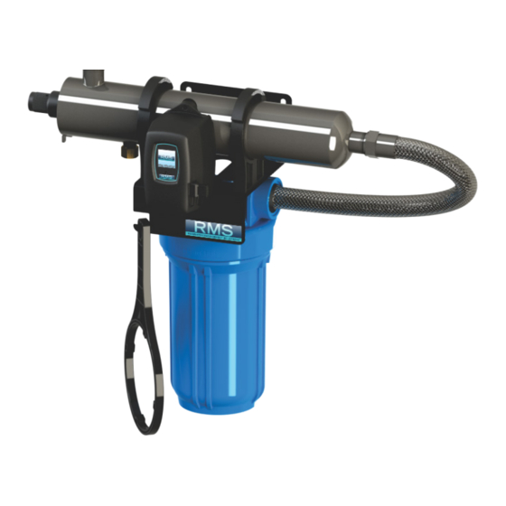
Operation & Installation Instructions
RMS5-R1
System
RMS4-R1
RMS5-R1
RMS4-R2
RMS5-R2
RMS4-R12
RMS5-R12
RMS4-R2C
RMS5-R2C
RMS4-R12C
RMS5-R12C
RMS4-R22C
RMS5-R22C
www.rainwatermanagement.com
RMS - Rack-Mount Systems
Rated Flow
8 gpm
8 gpm
8 gpm
15 gpm
15 gpm
15 gpm
RMS5-R22C
Sediment
Carbon
YES (10")
NO
YES (20")
NO
YES (10")
YES (20")
YES (20")
NO
YES (10")
YES (20")
YES (20")
YES (20")
Advertisement
Table of Contents

Related Manuals for RMS RMS5-R1

Summary of Contents for RMS RMS5-R1
- Page 1 Operation & Installation Instructions RMS5-R1 RMS5-R22C RMS - Rack-Mount Systems System Rated Flow Sediment Carbon RMS4-R1 8 gpm YES (10”) RMS5-R1 RMS4-R2 8 gpm YES (20”) RMS5-R2 RMS4-R12 8 gpm YES (10”) YES (20”) RMS5-R12 RMS4-R2C 15 gpm YES (20”)
- Page 2 This is chemical free process which is simple in its concept and effective in its abilities to inactivate microorganisms present in the water supply. Simple maintenance, continuous disinfection and ultimately safe water, RMS makes it that easy. P a g e...
-
Page 3: Table Of Contents
Lamp Replacement (RMS5 systems) ..............17 QR Codes ....................... 17 System Troubleshooting..................18 Temperature Management Devices ................. 19 Expansion Modules ......................20 RMS Rack-Mount UV System Specifications ..............21 Limited Warranty Statement: ................... 22 Warranty Registration ...................... 23 P a g e... -
Page 4: Safety Considerations
Safety Considerations Although your UV system has been manufactured to the highest safety standards, care must be followed when operating and/or maintaining your system. 1. Before servicing this equipment, disconnect the power cord from the electrical outlet. 2. Energy given off by the UV lamp is harmful to your eyes and skin. NEVER look directly at an illuminated UV lamp without adequate eye protection and always protect your skin from direct exposure to the UV light. -
Page 5: Water Quality Parameters
You can have your water tested at a private analytical laboratory or by your local dealer. It is always recommended to install pre-filtration of at least 5 microns prior to a RMS UV disinfection system. P a g e... -
Page 6: Assembly
Assembly The RMS rack-mount UV system is designed as a do-it-yourself (DIY) system with a single inlet and outlet port. Unpack the system and ensure all the components are included in the box. Your system is shipped with the following components:... -
Page 7: System Sizing
System Sizing All RMS UV systems are rated for a specific flow rate in water that meets the quality parameters on page 5. PLEASE NOTE increasing the flow above the system rating or disinfecting water that does not meet the quality parameters will decrease the dose and therefore compromise the microorganism inactivation. -
Page 8: Orientation
PLEASE NOTE: All RMS UV disinfection systems are intended for indoor use only as they should not be exposed to the elements. The controller will require a ground fault circuit interrupter (GFCI or GFI) outlet and should be mounted beside or above the reactor. -
Page 9: Installation
For water supplies where the maximum flow rate is unknown, a flow restrictor is recommended so that the rated flow of your particular RMS system is not exceeded. The flow restrictor should be installed on the inlet port of the reactor. - Page 10 Figure 5. Cartridge Removal Step 9: Install the UV sensor (RMS-S systems only). Align the flat portion so it faces the gland nut end and matches up with the half metal lip on the sensor port (see Figure 6). Insert the sen- sor so it is fully seated and hand tighten the sensor nut.
- Page 11 Step 15: Your system is now ready to be plugged into the appropriate GFCI protected outlet. Refer to the following section before any water is allowed to flow through the system. Note: Installation of your RMS disinfection systems shall comply with applicable provincial/state & local regulations.
-
Page 12: System Disinfection
Reinstall the filter cartridge into the sump and flush the chlorine solution by opening all faucets until chlorine can no longer be detected. Your home has now been completely disin- fected with your RMS UV system ready to inactivate any microorganisms that enter the home. Cleaning the Quartz Sleeve Depending on the water quality, the quartz sleeve may require periodic cleaning. -
Page 13: Cleaning The Uv Sensor
RMS systems come with a feature laden controller that incorporates both the lamp driver (bal- last) and control features in one water-tight case. Four main controllers are available for the RMS systems (depending on your model). All four models feature a power factor corrected, constant current lamp driver with a universal power input. -
Page 14: Rms4 Controllers
“infinite expandability port” located on the right side of the controller. Simply plug in an optional UV sensor module into the expandability port of a RMS controller and the system will now monitor the UV intensity of the system! -
Page 15: Rms4 & Rms4-C Operational Screens
On systems without the UV monitor, the default screen shows the RMS Home Screen. At any point during operation the user is able to scroll through the RMS Home Screen, Lamp life re- maining, QR Code, Contact Info and Maintenance Parts screens by pressing the button located on the front of the controller. -
Page 16: Rms4 & Rms6 Operational Screens
RMS5/RMS5-C Operational Screens On systems with the UV monitor, the system will display the same screens as on the RMS except the UV Intensity replaces the home screen. The UV Intensity screen displays the level of UV light detected by the sensor. UV intensity can be affected by poor water quality, scaling on the quartz sleeve and/or sensor, lamp failure or lamp expiring. -
Page 17: Lamp Replacement (Rms4 Systems)
A QR code (Quick Response code) is a matrix barcode first designed for the automotive industry. RMS uses the QR code to store a link to a specific page on our website. Users with a camera phone equipped with the correct reader application can scan the image of the QR code and over a wireless network connect to a RMS web page in the phone’s browser. -
Page 18: System Troubleshooting
System Troubleshooting Hard Alarms: The following give a constant audible alarm. If present, the solenoid valve is closed, and the 4-20, remote alarm and ethernet modules transmit the alarm. System Display Problem Resolution Reset lamp protection circuit -unplug unit for 10 seconds. The system has detected Replace the lamp with the a problem with the... -
Page 19: Temperature Management Devices
Warning: After any hard alarm, the home or facility should be disinfected. Follow the steps un- der the “System Disinfection” heading. Boil Water Advisory: If any failure occurs on a RMS UV system, the water must not be used for human consumption until the system is returned to a safe operational mode. -
Page 20: Expansion Modules
“daisy chain” configuration. The following optional expansion modules are available for use on RMS UV controllers. Contact your authorized distributor for purchasing information. -
Page 21: Rms Rack-Mount Uv System Specifications
Pressure Operating Water 2-40° C (36-104° F) Temperature UV Monitor OPTIONAL (optional UV module (RMS-S2) for RMS5, (RMS-S3) for RMS5-C, sold separately) Solenoid Output YES (optional solenoid module (MOD-SOL1-RMS) sold separately) Dry Contacts YES (remote alarm module (MOD-RAM-RMS) sold separately) -
Page 22: Limited Warranty Statement
(proper documentation required for veri- fication). RMS warrants that it will repair, replace or refund, at RMS’s sole option, any ultraviolet system or component that is defective in materials or workmanship for the period as outlined above, subject to the “Limitations of Warranty”... -
Page 23: Warranty Registration
Dealer or Distributor will contact RMS for instructions on return- ing the product. Any defective product to be returned to RMS must be sent freight prepaid; documentation supporting the warranty claim and/or a Return Material Authorization must be included if so instructed. - Page 24 Rainwater Management Solutions 2550 Shenandoah Ave. NW Roanoke, Virginia 24017 (866) 653-8337 www.rainwatermanagement.com PN#910300 Version Date: 05-2019...
Need help?
Do you have a question about the RMS5-R1 and is the answer not in the manual?
Questions and answers