Table of Contents
Advertisement
Quick Links
Advertisement
Table of Contents

Summary of Contents for GMS GDS-27
- Page 1 GDS-27 apaCitive level sensors INSTRUCTIONS MANUAL Read carefully the instructions published in this manual before the first use of the sensor. Keep the manual at a safe place. The manufacturer reserves the right to implement changes without prior notice...
-
Page 2: Table Of Contents
CONTENT 1. Brief ............................4 2. Features of variants ........................4 3. Dimensional drawings ........................5 4. Mounting recommendation ......................6 5. Range of application ........................10 6. Electrical connection........................11 7. Sensor setting..........................12 8. Status signalization........................13 9. Accessories ..........................14 10. Order code..........................15 11. Correct specification examples....................15 12. Safety, protections, compatibility .....................16 13. - Page 3 Sed SymbolS To ensure maximum safety of control processes, we have defined the following safety instructions and information. Each instruction is labeled with the appropriate pictogram. Alert, warning, danger This symbol informs you about particularly important instructions for installation and op- eration of equipment or dangerous situations that may occur during the installation and operation. Not observing these instructions may cause disturbance, damage or destruction of equipment or may cause injury.
-
Page 4: Brief
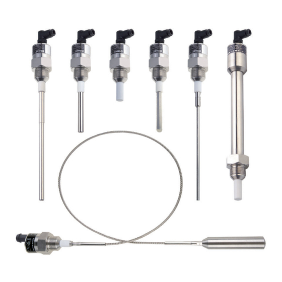
1. b rief Capacitive level sensors (switches) GDS are designed for limit level sensing of liquids, bulky solid ® and powder materials in vessels, containers, silos, tanks, reservoirs, etc. Sensors are made in several modifications of sensing electrodes – short and long rods or rope. The electrodes can be coated what has important sense in case of adhesive, aggressive or electrically conductive media sensing. The process coupling at the housing can be with thread M27x2, M30x1.5, G3/4” or with ... -
Page 5: Dimensional Drawings
3. d imenSional drawingS GDS – 27_ – 10 GDS – 27_ – 11 GDS – 27_ – 21, 22 GDS – 27_ – 30 GDS – 27_ – 20 Thead * * Type of threads: G 3/4'' M27x2 M30x1,5 GDS –... -
Page 6: Mounting Recommendation
Variants “B” Variants “C” Variants “D” with cable outlets with connector with cable outlets 4. m oUnting recommendation GDS level sensors can be fixed in a vertical, horizontal or bevelled position into the shell of the ves- sel, the storage tank for the fixation console in the pit, by screwing into the welding flange, using a fixing nut or TriClamp® process connection. Basic application recommendations are mentioned below. During assembly into the metal tank or the storage tank, it is not necessary to separately ground the base of the level sensor. - Page 7 In the case of side wall mount- ing it is necessary to avoid long fit- ting tubes, where could the rests of sensed media cumulate – see the right figure. We recommend to mount the sensor so that the whole sensing electrode is inside the con- tainer (vessel). All from side mounted sensor Fig.
- Page 8 GDS–27_–10 Fig. 3: Side wall mounting In the case of the application of the sensor in an electrically non-conductive (e.g. plastic) vessel in the vertical position, then for the correct function, it is recommended to connect the housing of the level sensor with an auxiliary electrode. The auxiliary electrode can consist of a bar which is permanently dipped into the medium (e.g. conductive probe CNP–18), or can be use the auxiliary ...
- Page 9 ≥ In the case of vertical mounting in outer are- Mounting in a bypass measuring tube. We ≥ as or in the case of high mechanical exertion recommend to keep the tube diameter. we recommend to install protective hose on For: GDS–27_–20, 21, 22, 30, 31 the cable. ≥ E –...
-
Page 10: Range Of Application
In the case of vertical mounting it is necessary to avoid long fitting tubes, where could the vapours condense or some rests sediment. right figure – wrong, left figure – appropri- ate. The similar situation is when the sensing electrode goes through the concrete ceiling of the silo. The hole diameter should be at least 50 mm (acc. -
Page 11: Electrical Connection
GDS –27_ –30 Is designed for universal use in vertical position for limit level detection of liquids (conductive and non-conductive) and bulk-solid and powder materials. It is not recommended to install the sensor into closed vessels where intensive condensation occurs. Electrically conductive liquids are sensed just by touch of the end of electrode. To react to non-conductive liquid or solid material it is neces- sary 5 ÷... -
Page 12: Sensor Setting
Electrical connection must be done in de-energized state! For switching supply sources, it is necessary to check that the input is galvanically separated from the network side and that they are fitted with a filter suppressing the conforming interference (terminals + and –... -
Page 13: Status Signalization
Activate the sensor by inundation (immersion) the electrode into the medium. With this activation, the sensor will change its status (LED lights ON or OFF). Lower the sensitivity (by clockwise turning) until the sensors stop to react to this activation (dipping into medium). The LED is in the same status as before the activation. Turn from ½ to 1 rotation left from the threshold point (when the sensor just stops its reaction to immersion). The sensor again changes the status and reacts again to the activation (flooding). Check the setting. If the medium is not available in advance, it is possible to use the basic setting from the producer and after some time of operation (after sedimentation of dirt) to make any correction. However, it is always necessary to know what the permittivity of the material is and to adapt the setting on the sensor. In the “Sensitivity characteristics” table it is stated for each type, where the change of capacity corresponds ... -
Page 14: Accessories
Level state Type of output Output state GDS–27N_–_ _– _ –NO–_ CLOSED GDS–27N_–_ _– _ –PO–_ (Shine) GDS–27N_–_ _– _ –NO–_ OPEN GDS–27N_–_ _– _ –PO–_ (Dark) GDS–27N_–_ _– _ –NC–_ CLOSED GDS–27N_–_ _– _ –PC–_ (Shine) GDS–27N_–_ _– _ –NC–_ GDS–27N_–_ _–... -
Page 15: Order Code
10. o rder code – – – – GDS – 27 Cable – Length of cable in m Length of electrode in mm Process connection: – Pipe thread G3/4" M27 – Metric thread M27x2 M30 – Metric thread M30x1,5 – Tri-clamp coupling Output state at non activated electrode: –... -
Page 16: Safety, Protections, Compatibility
14. g eneral conditionS and warranty GMS guarantees for the period of one (1) year that the product has the characteristic as in technical specification is mentioned. The guarantee can be invoked only when the product is completed by original invoice and guaran- tee list. -
Page 17: Specifications
15. S PecificationS echnical data Supply voltage performance GDS-27N 7 ... 36 V DC performance GDS-27Xd 7 ... 27 V DC Current supply (state OFF / ON) 3 / 10 mA * Max. switching current (NPN, PNP output) performance GDS-27N 200 mA performance GDS-27Xd 150 mA Remanent voltage – ON state Max. 1.5 V Output time delay 0.2 s Input resistance / Electric strength 1 MΩ / 1 kV AC... - Page 18 Sed materialS Part of the GDS Type Standard material * Housing All type W.Nr. 1.4301 (AISI 304) Teflon PTFE ® Insulating bushing All type (Polytetrafluoroethylene) W.Nr. 1.4301 (AISI 304) GDS-27_10,11,20,21,22,30,31 Electrode GDS-27_-40 W. Nr. 1.4404 (AISI 316 L ) Teflon PTFE ® Electrode coating GDS – 27_– 11 (Polytetrafluoroethylene) Teflon ® Electrode coating GDS –...
- Page 19 emPeratUre and PreSSUre dUrability Max. operating pressure for temperature t Variant / Performance Temp. Temp. Temp. to 30°C to 85°C to 120°C to 150°C to 180°C -40°C ... +100°C -25°C ... +85°C -20°C ... +80°C 3 MPa 2 MPa – –...
-
Page 20: Faq (Frequently Asked Questions)
Did you use the correct supply? It is necessary to use the source of the connected relay grumbles. DC smoothing voltage (not only rectified pulsing voltage), the best supply unit is GMS or another suitable stabilized source. The sensor does not have sharp switching, Is the hysteresis set on the sensor correctly? It will be necessary the connected relay during the transfer to increase the hysteresis by trimmer “H” (by turning in a clockwise ... - Page 21 #101-308, Digital Empire II Shinwon-ro 88, Yeongtong-gu, Suwon-si Gyeonggi-do, Korea Tel.: +82 31 243 1035 Fax: +82 31 243 1025 E-mail: export@gms-korea.com www.gmsko.com The lastest version of this instruction manual can be found at www.gmsko.com Version: 01/2017...
Need help?
Do you have a question about the GDS-27 and is the answer not in the manual?
Questions and answers