Table of Contents
Advertisement
Legion Solar Installation and Operations Manual
SAVE THIS MANUAL
Keep this manual for safety warnings, precautions, operating, installation, inspection, and
maintenance procedures. Write the product's device ID numbers in the back of the manual.
Read this material before using this product. Failure to do so can result in
serious injury, property damage, and/or electrical shock.
www.legionsolar.com
1
V3.1 March 26, 2021
+1 (408)745-7591
Advertisement
Table of Contents

Summary of Contents for PLX Legion Solar
- Page 1 Legion Solar Installation and Operations Manual SAVE THIS MANUAL Keep this manual for safety warnings, precautions, operating, installation, inspection, and maintenance procedures. Write the product’s device ID numbers in the back of the manual. Read this material before using this product. Failure to do so can result in serious injury, property damage, and/or electrical shock.
-
Page 2: Table Of Contents
Legion Solar Installation and Operations Manual Important Safety Information Read this First Safety Instructions Legion Solar Overview Included Items Location Planning Optimal Tilt Angle Optimal Direction Mounting Solutions Hardware Installation Install the MicroInverter to the Photovoltaic Panel Install the Battery Commander to the Photovoltaic Panel Install ‘Z’... - Page 3 Helpful 3rd Party Tools Maintenance Technical Data Device IDs PV Panel Drawing Part Descriptions 230VAC Micro Inverters on 120VAC Grids Legion Solar with Utility Approved Grid Tied Solar Systems Warranty Limitations of Liability Service and Support Copyright © 2021 PLX Devices Inc.
-
Page 4: Important Safety Information
This document contains instructions for use during installation and maintenance of Legion Solar System. To reduce the risk of electrical shock, and to ensure the safe installation and operation of Legion Solar System, pay close attention to following safety symbols that appear throughout this document. -
Page 5: Legion Solar Overview
Stage 1 - Get familiar with Legion Solar and it's components with the Starter Set. Sets up in minutes and experience instant results. A 300W Starter Set is enough to make a noticeable impact to your electric bill. - Page 6 Legion Solar Installation and Operations Manual Stage 3 - Once your system is large enough to have excess energy to store during daytime, add expansion sets with BatteryCommander™ for night time consumption. BatteryCommander™ enables the solar panels to charge the batteries, solar panels to supply power to the micro inverters, and batteries to supply power to the micro inverters.
-
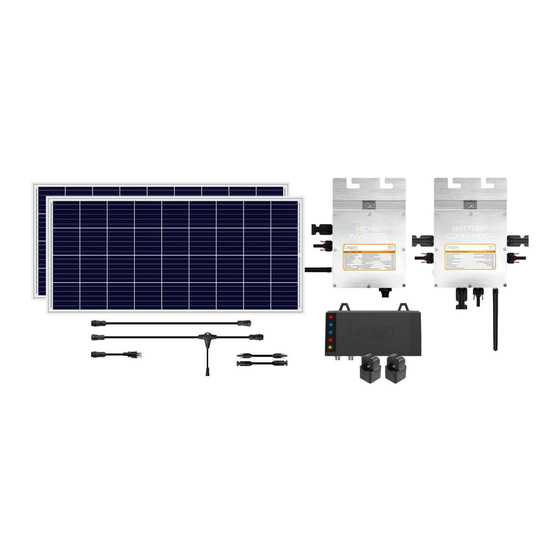
Page 7: Included Items
Legion Solar Installation and Operations Manual Included Items Legion Solar Starter Set • 1QTY Legion Solar Installation and Operations Manual • 1QTY Legion Solar Regulator with Bluetooth • 2QTY Split Core Transformers • 2QTY 150Watt LS-150P PhotoVoltaic Panels • 8QTY Aluminum ‘Z’ Brackets for DIY Mounting Solution •... -
Page 8: Location Planning
Legion Solar Installation and Operations Manual Location Planning Install the PV panels where the entire surface area is exposed to direct sunlight. Avoid any shaded areas to achieve maximum energy production. Optimal Tilt Angle Latitude Full Year Angle Latitude Full Year Angle 0°... -
Page 9: Mounting Solutions
All hardware components are automatically calculated. Items that you already own such as Starter and Expansion Sets can be removed from your shopping cart prior to check out. Individual Legion Solar components and accessories can also be purchased from www.plxdevices.com. Tap on LEGION SOLAR. - Page 10 (1) to locate your Antenna (2) out and above the PV panels for improved wireless performance and reliability. Use the included aluminum plate (3) designed to be installed on the Legion Solar End Clamp or Mid Clamp with a 1/4-20 nut (4). Copyright © 2021 PLX Devices Inc.
-
Page 11: Install The Battery Commander To The Photovoltaic Panel
(1) to locate your Antenna (2) out and above the PV panels for improved wireless performance and reliability. Use the included aluminum plate (3) designed to be installed on the Legion Solar End Clamp or Mid Clamp with a 1/4-20 nut (4). Install ‘Z’ Brackets for Do-it-Yourself Mounting Note: Skip this section if you are installing the PV panels on a roof racking rail system. -
Page 12: Electrical Installation
Legion Solar Installation and Operations Manual Step2: Place the ‘Z’ bracket over the oval hole and insert the Hex Screw Fine Thread 28 A2-70 0.25" x 5/8”. Step3: Insert the Washer A2-70 0.25”, followed by the Lock Washer A2-70 0.25”, then followed by Nut Fine Thread 28 A2-70 0.25.”... -
Page 13: Connect The Dc Wires (Inverter + Battery Commander)
Legion Solar Installation and Operations Manual Step4: Connect the plus (+) terminal from panel (B) to the MicroInverter. This connection may be easier to perform at the time of installation with racking system. Connect the DC Wires (Inverter + Battery Commander) -
Page 14: Connect The Battery (Lithium)
Lithium Batteries. This will cause damage and void your warranty. Step1: Battery Selection - Use Legion Solar 24V 100Ah Lithium Iron Phosphate Batteries ONLY. Legion Solar Lithium batteries have a built-in Battery Management System (BMS) designed specifically for use with Battery Commander 2.0 or later. -
Page 15: Connect The Battery (Lead Acid)
Install the battery posts with a 18mm wrench. Note the diameter size difference between the supplied posts with Legion Solar Lithium Batteries. Install the battery post with the larger diameter on the positive (+) terminal indicated on the battery in red with a + symbol. Install the smaller diameter battery post on the negative (-) terminals indicated on the battery in black with a - symbol. - Page 16 Legion Solar Installation and Operations Manual Step2: Install the (+) terminal over the positive battery terminal of battery A. Install the (-) terminal over the negative battery terminal of battery B. Tighten with 13mm wrench. Leave the (-) terminal of battery A and (+) terminal of battery B covered for safety.
-
Page 17: Connect The Ac Wires
Legion Solar Installation and Operations Manual Connect the AC Wires Step1: Connect the ’T’ Harness to the MicroInverter. Tip: As you bring a new system online, it is recommended that you test the system by connecting new sets in 300 watt intervals instead of bringing the entire system up all at once. -
Page 18: Grid Connection Method1: Plug And Play
Legion Solar Installation and Operations Manual Grid Connection Method1: Plug and Play Step1: Connect the T-Harness with the Straight-Harness Step2: Connect the Straight-Harness with the B-Plug. Step3A: Plug the B-Plug into your receptacle. Step3B: You may choose to extend the length of your wire with outdoor wire. -
Page 19: Grid Connection Method2: Hardwire
Legion Solar Installation and Operations Manual Grid Connection Method2: Hardwire Step1: Ensure the T-Harness and the Straight-Harness are NOT connected. Step2: Cut the male side of the Straight-Harness Step3: Obtain the following parts from your local hardware store in the electrical section. -
Page 20: Wire Selection Guide
Legion Solar Installation and Operations Manual Step6: Install the UF Cable Connector 1/2 in. Cut the insulation and strip the wires like the photo depicted. Refer to the wire size selection table below for sizing. Tip: Run cable inside grounded conduit pipe for improved durability and safety. -
Page 21: Ac Connection Schematic
Legion Solar Installation and Operations Manual AC Connection Schematic Copyright © 2021 PLX Devices Inc. -
Page 22: Expanding Your System
Legion Solar Installation and Operations Manual Expanding your System Copyright © 2021 PLX Devices Inc. -
Page 23: Installing Solar Regulator
Connect the split core transformers to Solar Regulator. Any transformer can be connected to any connector. Direction does not matter at this time. Once system calibration has been performed via Legion Solar App. Do NOT reverse connector positions, otherwise re-calibration must be performed. -
Page 24: Installing Off Grid Controller And Off Grid Inverter
Lead Acid Batteries. Off Grid Controller is NOT fused. When connecting Lead Acid batteries, ensure that the 150A Black Fuse Wire (supplied with Battery Commander) is installed for safety. When connecting Legion Solar Lithium Batteries, the 150A Black Fuse Wire is not used. The built-in Battery Management System will protect against short circuits. - Page 25 Legion Solar Installation and Operations Manual Step1: Install the black wire included with the Off Grid Inverter to the negative terminal of Off Grid Inverter. Use 10mm wrench to tighten. Hand tighten plastic nut over the plastic cover. Step2: Install the black wire to the negative terminal of Off Grid Controller.
- Page 26 Legion Solar Installation and Operations Manual Step4: Install the red wire to the positive terminal of Off Grid Controller. Use 10mm wrench to tighten. Hand tighten plastic nut over the plastic cover. Step5: Set Off Grid Inverter power switch to OFF position.
- Page 27 Legion Solar Installation and Operations Manual Step9: Install the red wire (stainless steel colored ring end) included with the Off Grid Controller to the Master+ terminal of Off Grid Controller. Use 10mm wrench to tighten. Hand tighten plastic nut over the plastic cover.
-
Page 28: Troubleshooting
Legion Solar Installation and Operations Manual Troubleshooting MicroInverters LED Indicator Located on the side of each MicroInverter is an LED indicator light to visually indicate the status of your energy production. Inverter LED Status Description No Light No DC Power or no sun light, AC Power may be present, check PV panel connections Red Blinking Low DC Power or low sunlight. -
Page 29: Battery Commander V1.0
Battery Commander in factory default mode. Disconnect battery and solar panel, wait 10 seconds and reconnect battery first, then solar panel. Set battery discharge limit above 40% in Legion Solar app. If problem persists. Contact customer service to send in the unit for repair. -
Page 30: Solar Regulator
Legion Solar Installation and Operations Manual Upon power-up the LED color is amber, followed by relay click sounds, then solid green LED to indicate that Battery Commander V1.0 has successfully started and initialized. Solar Regulator 5 LED Indicators Located on the side of the SolarRegulator are indicator lights to describe various operational parameters. -
Page 31: Off Grid Inverter
Legion Solar Installation and Operations Manual Status Master Slave 1 Slave 2 Slave 3 Battery Supplying Power to Inverter Green Green Green Green Upon power-up, 4 click sounds indicate that Off Grid Controller has successfully started and initialized. Off Grid Inverter... - Page 32 Legion Solar Installation and Operations Manual Ground and Outlet Tester A useful tool for plug and play AC installation to test and validate your outlet’s connection for proper ground, hot and neutral wiring. Sponge Mop A low cost solution for cleaning your PV panels to keep them running at peak efficiency.
-
Page 33: Maintenance
Run system diagnostics and health checks at least once a month via Legion Solar app. Sealed lead acid batteries start to degrade after about 400 charge cycles. Monitor for weak cells and replace the batteries as necessary. - Page 34 Legion Solar Installation and Operations Manual LS-260IG4 MicroInverter 260W (OK for use with Battery Commander 1.0 and 2.0) 120VAC 230VAC Maximum Output Power 300W (Solar), 260W (Batteries) 300W (Solar), 260W (Batteries) Maximum Output Current 2.36A 1.18A Maximum Efficiency 95.5% Output Voltage Range...
- Page 35 Legion Solar Installation and Operations Manual LS-260IG3 or G3B MicroInverter 260W (Do NOT use with Battery Commander 2.0) 120VAC 230VAC Maximum Output Power 260W (Solar), 220W (Batteries) 260W (Solar), 220W (Batteries) Maximum Output Current 2.36A 1.18A Maximum Efficiency 95.5% Output Voltage Range...
- Page 36 Legion Solar Installation and Operations Manual LS-BC Battery Commander V2.0 Inverter Compatibility Legion Solar Micro Inverter Only Solar Panel 200-320W 72 Cell Battery Type Lithium Iron Phosphate 24V, Deep Cycle Sealed Lead Acid 24V Operating Temperature -40° C to 80° C...
- Page 37 Legion Solar Installation and Operations Manual LS-Regulator Legion Solar SolarRegulator Voltage 120/230 VAC Frequency 60/50 Hz Power Consumption 2.5 Watts Typical Operating Temperature -40º C to +80º C Water/Dust IP65 Communication Mode Wireless 2.4 GHz Interface Bluetooth 5 Monitoring Capability 32 Micro Inverters (9.6kW) + 32 Battery Commanders...
-
Page 38: Device Ids
Legion Solar Installation and Operations Manual Device IDs Write down the device ID of your MicroInverters and Battery Commanders. IDs are 6 characters long and can be found on the front side of your units. Devices IDs are used during setup and system calibration. Be sure to write down the Battery Commander ID that is specifically paired with the Inverter ID for each set. -
Page 39: Pv Panel Drawing
Legion Solar Installation and Operations Manual PV Panel Drawing Copyright © 2021 PLX Devices Inc. -
Page 40: Part Descriptions
Legion Solar Installation and Operations Manual Part Descriptions Copyright © 2021 PLX Devices Inc. -
Page 41: 230Vac Micro Inverters On 120Vac Grids
If you already have a utility approved grid tied solar system where permission to back feed has already been granted, you may use Legion Solar to produce more energy. Simply setup the system as normal. In the Legion Solar app, when asked to calibrate, tap skip calibration. Once the setup is complete perform the following steps. -
Page 42: Limitations Of Liability
Limitations of Liability Using and installing any component of Legion Solar you agree to hold that PLX Devices Inc. shall in no event be liable for death, injuries to persons or property, or for incidental, contingent, special or consequential damages arising from the use of our products.
Need help?
Do you have a question about the Legion Solar and is the answer not in the manual?
Questions and answers